LFC System of Multi-Area Interconnected Power
Systems using TVAC-PSO based Controller
K. P. Singh Parmar
Assistant Professor National Power Training Institute Faridabad, Haryana, 121003, India
ABSTRACT
This article presents a Particle Swarm Optimization with time-varying acceleration coefficients (TVAC-PSO) technique for the design of Integral (I) controller for the Load Frequency Control (LFC) system. The LFC modeling is carried out for Multi-area interconnected power systems (MAIPS). The power system comprises non-reheat thermal unit in each control area. The controller gains have been optimized using an efficient TVAC-PSO technique. Two MAIPS models have been considered for the LFC analysis. The dynamic responses have been obtained by giving step load perturbation (SLP) in control area-1. Area frequency and tie line power deviations settle with zero steady state errors. Area frequencies and tie line powers attain their corresponding nominal values. The dynamic responses obtained are as per the LFC requirements.
General Terms
Control area, Frequency deviation, Tie line power deviation, Particle Swarm Optimization
Keywords
Integral Controller, Load Frequency Control, Load Perturbation, Multi-area
1.
INTRODUCTION
LFC problem has been considered as one of the most important and recent topics of research and development in interconnected power systems [1-4]. Literature survey on LFC shows that this problem has been a topic of research over a long period [5]. Due to load perturbations in the power system, it experiences deviations in frequency and tie line power [1-4]. Main task of the LFC system is to settle the control area frequency and tie line power deviations [1-4]. This task can be accomplished by maintaining a balance between actual power (MW) generation and load demand. Thus, LFC plays a vital role in maintaining the frequency and tie line powers at their corresponding scheduled values.
Many researchers [5, 6-24] presented LFC schemes with different control strategies to a variety of power system models. Optimal control theory based controllers have been presented for the LFC analysis of power systems [6-10, 22-23]. Parmar et al. [6-8] presented the output feedback controllers for the LFC schemes of power systems. Applications of thyristor controlled phase shifter (TCPS) [9] and AC-DC tie lines [10] are reported for LFC of multi-source two area power systems to improve the dynamic responses.
A LQG based load frequency controller is used for LFC analysis in competitive electricity environment [23].
Several Artificial intelligence (AI) techniques and Evolutionary algorithms have been applied by researchers for
LFC schemes of power systems [5, 12-21]. Advancement of modern computational methods and Evolutionary algorithms, such as Particle swarm optimization (PSO), PSO-hybrids, Artificial neural networks (ANNs), Fuzzy logic, Genetic algorithms(GAs) based optimization has provided the efficient solutions to the LFC problems [5, 12-21]
Type-2 Fuzzy approach [17] and Variable structure Fuzzy gain scheduling [18] approach is applied for LFC study of interconnected power systems. LFC schemes using Fuzzy proportional plus integral (PI) controllers are reported in literature [14, 15]. GA/PSO based optimization has been applied to the automatic generation control [16]. The GA technique faces some deficiencies like premature convergence which degrades its efficiency and reduces the search capability [5, 21]. Shayeghi and Shayanfar [12] have applied a H∞ robust control technique for training of Radial basis function (RBF) Neural networks for improving the performance of the LFC controllers. A detailed literature survey contained in [5] concludes that many controllers and optimization techniques have been used by the researchers to solve the LFC problem and each controller presented has its own advantages and disadvantages. PSO and improved/ modified PSO techniques have emerged as important and powerful tools to solve the various engineering problems [5, 16, 20, 21, 26-31].
Padhan and Majhi [24] applied a PID controller with a new structure to LFC of single area and four areas interconnected power systems. Ibraheem and Singh [20] designed a PSO based automatic generation control regulator with different cost functions for three area power system. In this present paper, an improved method TVAC-PSO [29] has been applied to present the LFC systems of three unequal areas interconnected power system initially and further, extended to five unequal areas interconnected power system. MATLAB Simulink Software [32] is used to simulate the power system LFC schemes. The proposed strategy yields promising results.
2.
PSO WITH TIME-VARYING
ACCELERATION COEFFICIENTS
been applied in many engineering problems to optimize the parameters [16, 20, 30-31].
In this present paper, TVAC-PSO [29] strategy has been applied to LFC system. Time varying acceleration coefficients (TVAC) [29] improves the global exploration in the early part of the process and enhances the convergence of the particles in the later stages of the process. This is accomplished by varying the acceleration coefficients and with time in such a way that the cognitive component reduces and the social component increases with increase in iterations. In brief, at the beginning of the process, a large cognitive component and a small social component help the particles to explore the search space in a better way while at later stages of the process, a smaller cognitive component and a larger social component allow the particles to converge to the global optima. The time varying acceleration coefficients can be given as [29]:
(1)
(2)
Where , , and are initial and final values of the
cognitive and social acceleration coefficients respectively.
In the PSO strategy [26], the particle’s best position,
and global best position, are the key factors. The
position with minimum objective function value is the particle’s best position. The best position out of all the
is taken as . Particles in the swarm are accelerated to
new positions by adding new velocities to their current positions.
The new velocity is calculated using the following equation:
= * w +
*rand( )*( ) +
*Rand( )*( )
(3)
and the positions of the particles are updated using the following equation:
= +
(4)
If the evaluation value of each particle is better than previous , the current value is set to . If the best is better than , this new value is set as .
An objective function value at is set as Jbest. More
details on algorithm and strategy are contained in [1, 20, 26, 29].
TVAC-PSO gives better computational results as compared to PSO by effectively controlling the global search and convergence to the global best solution [29]. This method avoids premature convergence in the early stages of the search and enhances convergence to the global optimum solution during the latter stages of the search [29]. The PSO-TVAC has been compared with several methods and found that it gives better results in various engineering problems [29, 31]. In this paper, TVAC-PSO method has been applied to LFC system of MAIPS and extensive simulations have been carried out. The results obtained are satisfactory.
3.
MAIPS MODELLING AND
PARAMETER OPTIMIZATION
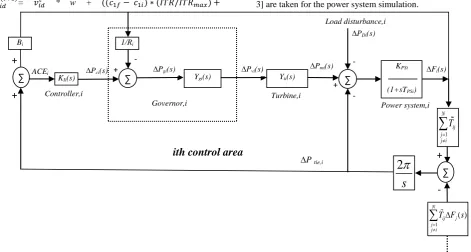
[image:2.595.59.531.427.679.2]MAIPS is taken for LFC study in this paper. The ith control area of the MAIPS is modeled as shown in the Fig.1. Each control area of the power system comprises a thermal unit. The non-reheat steam turbine and governor dynamics [1-3] are taken for the power system simulation.
Fig. 1: ith control area of a MAIPS with N control areas
The MAIPS representation in Fig. 1 and further simulations extended to three unequal areas and five unequal areas power systems for the LFC study are based on the concepts described in literature [1-4, 20, 24].
Some important and useful equations and dynamics are presented for better understanding of the readers. The dynamics of the governor ( )
gi
Y s
and non-reheat steam
Ygi(s) Yti(s)
∆PDi(s)
+ -
∆Pmi(s)
∆Pvi(s)
∆Pgi(s)
∆Pci(s) KPSi
(1+sTPSi)
+ -
∆Fi(s)
1/Ri
Governor,i
Turbine,i
Power system,i
KIi(s)
Bi
Controller,i
∆P tie,i
∑
+
+
ACEi
- Load disturbance,i
2
s
1
N
ij j j i
T
+
1 ( )
N
ij j j j i
T F s
-
ith control area
∑
∑
turbine ( )
ti
Y s
can be described [1-3] by equations (5) and (6), respectively as follow:
1
( )
1
giSGi
Y
s
sT
(5)
1
( )
1
tiTi
Y s
sT
(6)
Where, TSGi and TTi are time constants of speed governor and
non-reheat steam turbine, respectively.
The total incremental change in tie line power
P
tie i, in pu MW between control area-i and all other connected control areas as shown in Fig. 1 can be given as, ,
1 1 1
2
( ) ( ) ( ) ( )
N N N
tie i tie ij ij i ij j
j j j
j i j i j i
P s P s T F s T F s
s
(7)
Where,
, tie ij
P
is incremental change in actual tie line power flow from control area i to j, pu MW,ij
T
is tie line synchronizing coefficient between control area i and j,i
f
is incremental change in frequency of ith control area, N is number of control areas., tie ji
P
the incremental change in actual tie line power flow from control area j to i, pu MW, can be expressed as, ,
tie ji ij tie ij
P
a
P
(8)
Where,
a
ij is the control area capacity ratio [2] and defined asrated capacity of
rated capacity of
area-ij
i
a
j
The signal fed into the controller in secondary loop is referred to as area control error (ACE). The ACE of ith control area can be defined [1-3] as
,
i tie i i i
ACE
P
B f
(9)Where,
i
B
is the frequency bias parameters of ith control area. As I-controller is applied in the secondary loop of LFCsystem, the controller signal command
P
cito the speed changer of ith area will thus become
dtci Ii i
P K ACE
(10) Where,
Ii
K
is the gain of the Integral controller of the ith area. The minus sign is included since each area of the power system should increase its generation level if either its frequency error or its tie line power increment is negative [1-3].The controller gains (KIi for i=1 to N)have been optimized by
minimizing the performance index (J) using the efficient TVAC-PSO technique as described in previous section.
The main aim of the controller is to minimize the frequency and tie line power deviations and bring the frequency and tie line power at their corresponding nominal values. The performance index for the presented controller is defined using the Integral square error (ISE) criteria as follow:
2 2
,
1 1 1
0
(
)
T N N N
i tie ij
i j i
j i
J
f
P
dt
(11)Where, T is the simulation time.
4.
SIMULATION RESULTS AND
DISCUSSION
4.1
Power System Model-1
A three unequal area interconnected power system is considered for LFC system. Each control area comprises non-reheat thermal unit. The ith control area of the interconnected power system is shown in the Fig. 1 where number of interconnected control areas (N) is three. 1000MW, 2000MW and 4000MW are the rated capacities of the area-1, 2 and 3, respectively. 50% nominal load is assumed for each area. 1% SLP is given in the control area-1. The nominal power system parameters are taken from [1-3] and given in Appendix A.
A MATLAB code based on TVAC-PSO algorithm has been used in MATALB Environment [32] to obtain the optimized controller gains. The PSO parameters are given in Appendix A. The convergence characteristic of the TVAC-PSO algorithm for the power system is shown in Fig. 2. The minimum value of the J becomes 0.00031862.
Optimized controller gains are:
KI1= 0.448668896293008
KI2=0.012400000000000
KI3=0.013200000000000
Fig. 2: Convergence characteristics of TVAC-PSO technique
Fig. 3: Frequency deviation response, area-1
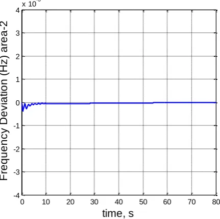
Fig. 4: Frequency deviation response, area-2
Fig. 5: Frequency deviation response, area-3
[image:4.595.327.522.280.444.2]Fig. 6: Net tie line power deviation response, area-1
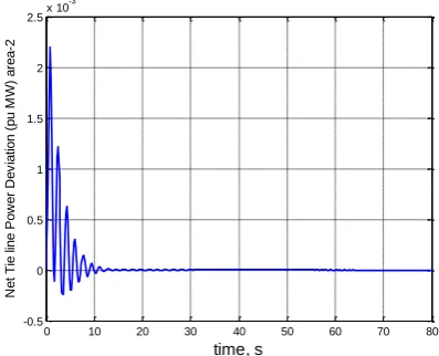
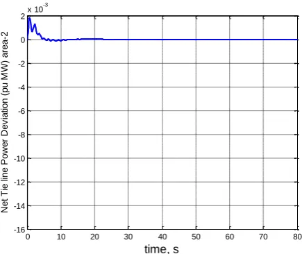
Fig. 7: Net tie line power deviation response, area-2
0 20 40 60 80 100
3.186 3.1865 3.187 3.1875 3.188 3.1885 3.189 3.1895 3.19 3.1905x 10
-4
No. of iterations
P e rf o rm a n c e I n d e x J
0 10 20 30 40 50 60 70 80 -0.02 -0.015 -0.01 -0.005 0 0.005 0.01 time, s F re q u e n c y D e v ia ti o n ( H z ) a re a -1
0 10 20 30 40 50 60 70 80 -6 -5 -4 -3 -2 -1 0 1x 10
-3 time, s F re q u e n c y D e v ia ti o n ( H z ) a re a -2
0 10 20 30 40 50 60 70 80 -4.5 -4 -3.5 -3 -2.5 -2 -1.5 -1 -0.5 0 0.5x 10
-3 time, s F re q u e n c y D e v ia ti o n ( H z ) a re a -3
0 10 20 30 40 50 60 70 80 -12 -10 -8 -6 -4 -2 0 2x 10
-3 time, s N e t T ie l in e Po w e r D e v ia ti o n (p u M W ) a re a -1
0 10 20 30 40 50 60 70 80 -0.5 0 0.5 1 1.5 2 2.5x 10
[image:4.595.324.523.481.642.2] [image:4.595.67.273.492.665.2]Fig. 8: Net tie line power deviation response, area-3
4.2
Power System Model-2
A five unequal areas interconnected power system is considered for LFC system. Each control area comprises non-reheat thermal unit. The ith control area of the interconnected power system is shown in the Fig. 1 where number of interconnected control areas (N) is five. 1000MW, 2000MW, 4000MW, 5000MW and 6000MW are the rated capacities of the control area-1, 2, 3, 4 and 5, respectively. 50% nominal load is assumed for each area. 1% SLP is given in the control area-1. The nominal power system parameters used are given in Appendix A.
The optimized controller gains have been obtained using MATLAB code based on TVAC-PSO algorithm. The PSO parameters are given in Appendix A. The algorithm exhibits good convergence characteristics and minimum value of the J becomes 0.0002594.
Fig. 9: Frequency deviation response, area-1
Optimized controller gains computed are given below:
KI1=0.322860667755127
KI2=0.010200000000000
KI3=0.025739565704346
KI4=0.750618034210205
K =0.012400000000000
[image:5.595.326.542.168.382.2]System simulation results are obtained with the optimized controller gains. The frequency and tie line power deviation responses have been obtained for all the five areas and examined. The examination reveals that frequency and tie line power of all the areas settle to their corresponding nominal values. For sample, the dynamic responses of 1 and area-2 are shown in Figs 9-1area-2. Thus, all the dynamic responses satisfy the LFC requirements.
Fig. 10: Frequency deviation response, area-2
Fig. 11: Net Tie line power deviation response, area-1
0 10 20 30 40 50 60 70 80 -2
0 2 4 6 8 10 12 14 16x 10
-4
time, s
N
e
t
T
ie
l
in
e
Po
w
e
r
D
e
v
ia
ti
o
n
(p
u
M
W
)
a
re
a
-3
0 10 20 30 40 50 60 70 80 -0.015
-0.01 -0.005 0 0.005 0.01 0.015
time, s
F
re
q
u
e
n
c
y
D
e
v
ia
ti
o
n
(
H
z
)
a
re
a
-1
0 10 20 30 40 50 60 70 80
-4 -3 -2 -1 0 1 2 3 4x 10
-3
time, s
F
re
q
u
e
n
c
y
D
e
v
ia
ti
o
n
(
H
z
)
a
re
a
-2
0 10 20 30 40 50 60 70 80 -16
-14 -12 -10 -8 -6 -4 -2 0 2x 10
-3
time, s
N
e
t
T
ie
l
in
e
Po
w
e
r
D
e
v
ia
ti
o
n
(p
u
M
W
)
a
re
a
[image:5.595.318.538.411.600.2] [image:5.595.56.282.470.644.2]Fig. 12: Net Tie line power deviation response, area-2
5.
CONCLUSION
TVAC-PSO based LFC systems of MAIPS have been presented. The power system comprises non reheat thermal unit in each control area. The effectiveness of the proposed strategy has been demonstrated on two MAIPS where; first one has three unequal areas and the second one has five unequal areas. MATLAB simulations are carried out with optimized controller gains for the LFC of presented power systems. The TVAC-PSO algorithm gives potential convergence characteristics. The dynamic responses are obtained by giving 1% SLP in control area 1. An extensive analysis is done. Area frequencies and tie line power deviations settle quickly and the dynamic responses are less oscillatory. Thus, the area frequencies and tie line powers attain their corresponding nominal/scheduled values. The TVAC-PSO based I controller is efficient to yield the desired LFC characteristics.
APPENDIX A
Power System and PSO Parameters
120 Hz/pu MW,
20 s,
0.06 s,
0.3 s,
0.0866,
2.4 Hz/puMW,
0.425 puMW/Hz,
Nominal loading=50%
PSO Parameters:
Simulation time,T = 80s,
Population size = 40,
Maximum iterations = 1
PSi PSi
SGi Ti ij
i i
K
T
T
T
T
R
B
max min
00,
w
= 1.2, w
= 0.3
6.
REFERENCES
[1] Kothari DP, Nagrath IJ. Modern power system analysis. 4th ed. New Delhi: Tata McGraw Hill; 2011.
[2] Elgerd OI. Electric energy system theory: an introduction. 2nd ed. New York: McGraw Hill; 1983.
[3] Kundur P. Power system stability and control. 5th reprint. New Delhi: Tata McGraw Hill; 2008.
[4] Bevrani H. Robust power system frequency control. New York: Springer; 2009.
[5] Ibraheem, Kumar P, Kothari DP. Recent philosophies of automatic generation control strategies in power systems. IEEE Trans Power Syst 2005;20(1):346–57.
[6] Parmar KPS, Majhi S, Kothari DP. Load frequency control of a realistic power system with multi-source power generation. Int J Electr Power Energy Syst 2012;42:426–33.
[7] Parmar KPS, Majhi S, Kothari DP. Automatic generation control of an interconnected hydrothermal power system. In: IEEE conference on proceedings, INDICON. Kolkata, India; 2010.
[8] Parmar KPS, Majhi S, Kothari DP. Multi-area load frequency control in a power system using optimal output feedback method. In: IEEE conference on proceedings, PEDES. New Delhi, India; 2010.
[9] Parmar KPS, Majhi S, Kothari DP. LFC of an interconnected power system with thyristor controlled phase shifter in the tie line. Int J Comput Appl 2012;41(9):27–30.
[10]Parmar KPS, Majhi S, Kothari DP. Improvement of dynamic performance of LFC of the two area power system: an analysis using MATLAB. Int J Comput Appl 2012;40(10):28–32.
[11]Yazdizadeh A, Ramezani MH, Hamedrahmat E. Decentralized load frequency control using a new robust optimal MISO PID controller. Int J Electr Power Energy Syst 2012; 35:57–65.
[12]H. Shayeghi, H. A. Shayanfar. Application of ANN technique for interconnected power system load frequency control. Int J Eng., vol. 16, no. 3, pp. 247 – 254, 2003.
[13]S. Ramesh, A. Krishnan. Fuzzy rule based load frequency control in a parallel AC-DC interconnected power system through HVDC link. International Journal of Computer Applications, vol. 1, no. 4, 2010.
[14]C. S. Chang, W. Fu. Area load frequency control using fuzzy gain scheduling of PI controllers. Electr Power Syst Res, vol. 47, pp. 145 – 152, 1997.
[15]E. Cam, I. Kocaarslan. Load frequency control in two area power system using fuzzy logic controller. J. Energy Conversion and Management, vol. 45, pp. 233 – 245, 2005.
[16]P. Bhatt, R. Roy, and S. Ghoshal. GA/particle swarm intelligence based optimization of two specific varieties of controller devices applied to two-area multi-units automatic generation control. Int. Journal of Electrical Power and Energy Syst., vol. 32, no. 4, pp. 299 – 310, May 2010.
[17]Sudha KR, Santhi RV. Robust decentralized load frequency control of interconnected power system with generation rate constraint using type-2 fuzzy approach. Int J Electr Power Energy Syst 2011;33:699–707. 0 10 20 30 40 50 60 70 80
-16 -14 -12 -10 -8 -6 -4 -2 0 2x 10
-3
time, s
N
e
t
T
ie
l
in
e
Po
w
e
r
D
e
v
ia
ti
o
n
(p
u
M
W
)
a
re
a
[18]Chandrakala KRMV, Balamurugan S, Sankaranarayanan K. Variable structure fuzzy gain scheduling based load frequency controller for multi-source multi-area hydro thermal system. Int J Electr Power Energy Syst 2013;53:375–81.
[19]Panda S, Yegireddy NK. Automatic generation control of multi-area power system using multi-objective non-dominated sorting genetic algorithm-II. Int J Electr Power Energy Syst 2013;53:54–63.
[20]Ibraheem, Omveer Singh. Design of particle swarm optimization (PSO) based automatic generation control (AGC) regulator with different cost functions. Journal of Electrical and Electronics Engg. Res. Vol. 4(2), pp. 33-45, November 2012.
[21]Bevrani H, Hiyama T. Intelligent automatic generation control. New York: CRC Press; 2011.
[22]Tyagi B, Srivastava SC. A decentralized automatic generation control scheme for competitive electricity markets. IEEE Trans Power Syst 2006;21(1):312–20.
[23]Tyagi B, Srivastava SC. A LQG based load frequency controller in a competitive electricity environment. Int J Emerging Elect Power Syst (online) 2005:2. <http://www.bepress.com/ijeeps/vol2/iss2/art1044>.
[24]Padhan DG, Majhi S. A new control scheme for PID load frequency controller of single area and multi area power systems. ISA Transactions, vol. 52, pp.242-251, 2013.
[25]IEEE power engineering systems committee report. Dynamic models for steam and hydro turbines for power
systems studies. IEEE Trans Power App Syst 1973;PAS-92.
[26]J. Kennedy, R. Eberhart. Particle swarm optimization. Proceedings of IEEE Int. Conf. on Neural Networks, vol. 4, pp. 1942-1948, 1995
[27]Y. Shi, R. Eberhart. A modified particle swarm optimizer. Proceedings of IEEE Int. Conf. on Evol. Comput., pp. 69-73, 1998
[28]Y. Shi, R. Eberhart. Empirical study of particle swarm optimization. Proceedings Congr. Evol. Comput., NJ, pp. 1945-1950, 1999
[29]A. Ratnaweera, S. K. Halgamuge, H. C. Watson. Self-organizing hierarchical particle swarm optimizer with time varying acceleration coefficients. IEEE Trans. on Evol.Comput., vol. 8, no. 3, pp. 240-255, 2004
[30]Ma. Y, C. Jiang, Z. Hou, C. Wang. The formulation of the optimal strategies for the electricity producers based on the particle swarm optimization algorithm. IEEE Trans. on Power Systems, vol. 21, no. 4, pp. 1663-1671, 2006
[31]Bhuvnesh Khokhar, K.P. Singh Parmar. An efficient particle swarm optimization with time varying acceleration coefficients to solve economic dispatch problem with valve point loading. Journal of Energy and Power, vol. 2(4), pp. 74-80, 2012