DN1769-0909 v01.00
Installation Manual
Kantech Telephone Entry System
DN1769-0909 iii
Table of Contents
General Description ... 1
Pre-Installation Information...1
Copyright Information ...1
Safety Instructions ...1
Technical Support...2
Compliance Specifications...3
Overview...5
Features ...6
Optional Accessories...7
1 - System Architecture...11
2 - Technical Specifications...15
3 - Electrical Specifications ...16
4 - Installing the KTES ...17
4.1 Preparing to Install the KTES ...17
4.2 Installation ...17
5 - KTES Models, Options, Related Documentation and Miscellaneous Items...25
6 - Troubleshooting ...27
7 - Heartbeat Patterns...28
8 - Hardware Default initialization ...29
8.1 How to reset the Kantech Telephone Entry System for Factory Default ...29
9 - Maintenance Recommendations ...30
DN1769-0909 1
General Description
Pre-Installation Information
To the Installer: If you are familiar with the installation, you can jump to section 4 - Installing the KTES or use the
Appendix A - Installation Checklist on page 31 of this manual.
Copyright Information
© 2009 Tyco International Ltd. and its Respective Companies. All Rights Reserved. All specifications were current as of publication date and are subject to change without notice. Kantech and the Kantech logo are trademarks of Tyco International Ltd. and its Respective Companies.
Safety Instructions
Important: NEVER INSTALL THE EQUIPMENT DURING A LIGHTNING STORM!
This equipment, Kantech Telephone Entry System, shall be installed and used within an environment that provides the pollution degree max 2 and over voltages category II NON HAZARDOUS LOCATIONS, INDOOR and OUTDOOR. The equipment is FIXED and PERMANENTLY CONNECTED and is designed to be installed by Service Persons only; [service person is defined as a person having the appropriate technical training and experience necessary to be aware of hazards to which that person may be exposed in performing a task and of measures to minimize the risks to that person or other persons.] The equipment is installed in a metallic cabinet that meets the applicable requirements for a FIRE ENCLOSURE.
1.The connection to the mains supply must be made as per the local authorities rules and regulations: In the UK as per BS6701. An appropriate disconnect device must be provided as part of the building installation. Where it is not possible to rely on the identification of the NEUTRAL in the AC MAINS SUPPLY, the disconnecting device must disconnect both poles simultaneously (LINE and NEUTRAL).
• Be permanently connected, fail safe, with double or reinforced insulation between primary and secondary circuits.
• The ground connection must be provided by the TERMINAL BLOCK at the PE (IEC 60417-5019 symbol) marked connection. It is the installer’s responsibility to provide protection against a short circuit on the input (bridge rectifier, C2, etc.).
• The system requires the integrity of the subscribed telephone line to be operational at all times. If the telephone line is cut off, placed out of service, or shared with other interconnect telephone devices other than the KTES, the unit will not be able to perform its function when required.
2.AVOID setting up the equipment near heaters, air conditioners, ventilators. DO NOT select a place that exposes the KTES to vapors, chemicals or dust.
3.If during the installation a knockout on the cabinet is removed, it is the installer's responsibility to ensure that the same degree of protection for the cabinet is provided by the use of bushings, fittings, adequate sealant, etc. 4.The metallic cabinet must be secured to the building structure before operation.
5.The ground connection must be as shown within the included diagram, or equivalent. 6.Internal wiring must be routed in a manner that prevents:
• Excessive strain on wire and on terminal connections;
• Loosening of terminal; connections;
• Damage of conductor insulation.
7.It is the end-user and/or installer's responsibility to ensure that the disposal of the used batteries is made according to the waste recovery and recycling regulations applicable to the intended market.
8.There are no serviceable parts within the equipment; For any issues regarding the equipment please contact your installer.
9.CAUTION: To reduce the risk of fire, use only AWG #26 or larger telecommunication line cord.
10.CAUTION: Risk of explosion if battery is replaced by an incorrect type. Dispose of used batteries according to the instructions.
11.Sealant application is required on all mounting holes and removed knockouts. The draining holes must not be blocked by any excess of sealant.
Technical Support
For technical assistance with the Kantech Telephone Entry System and other Kantech products, contact technical support, Monday to Friday. See the following table for the technical support phone numbers.
Country/Region Phone Numbers Support Hours Email
North America Toll Free +888 222 1560 (GMT -05:00)
US and Canada Direct: +450 444 2030Fax: +450 444 2029 8:00 to 20:00 [email protected]
Latin America (GMT -03:00)
Argentina
Direct: +5411 4717 2929 Direct: +5411 4717 1320 Direct: +5411 4717 5525 Fax: +5411 4717 1060
9:00 to 18:00 [email protected]
Asia (GMT +08:00)
Singapore
Direct: +65 6319 9820 Fax: +65 6319 9821 Direct: +65 6389 8297
Fax: +65 6389 8292
8:30 to 18:00 [email protected][email protected]
Europe Toll Free +800 CALL TYCO / +800 2255 8926 (GMT +01:00)
Bahrain +800 04127
8:00 to 18:00 [email protected]
France +33 04 72 79 14 83
Greece +00 800 31 22 94 53
Russia +8 10 800 2052 1031
Spain +900 10 19 45
Turkey +00 800 31 92 30 37
United Arab Emirates +800 0 31 0 7123
United Kingdom
+44 08701 ADT SUP / 44 08701 238 787 Direct: +31 475 352 722
DN1769-0909 3
Compliance Specifications
FCC & IC Compliance
• This device complies with FCC 2000 Part 15 Class B (Radiated Emissions, Residential, USA). Operation is subject to the following two conditions: (1) this device may not cause harmful interference, and (2) this device must accept any interference received including interference that may cause undesired operation. This class B digital apparatus meets all requirements of the Canadian Interference Causing Equipment Regulations. The Kantech Telephone Entry System is also compliant with EN55022:1998, amendment 1:1995, Class B and CISPR 22.
• TIA968 (FCC part 68) Direct Connection to the PSTN (Public Switched Telephone Network) USA.
• FCC Registration Number: ACTA US: V85OT01BKTES125 REN: 01B
• DOC - CANADA: The Canadian Department of Communications label identifies certified equipment. This certification means that the equipment meets certain telecommunications network protective, operational, and safety requirements. The Department does not guarantee the equipment will operate to the users satisfaction.
-Before installing this equipment, users should ensure that it is permissible to be connected to the facilities of the local telecommunications company. The equipment must also be installed using an acceptable means of connection. The customer should be aware that compliance with the above conditions may not prevent degradation of service in some situations.
-Repairs to certified equipment should be made by an authorized Canadian maintenance facility designated by the supplier. Any repairs or alterations made by the user to this equipment, or equipment malfunctions, may give the telecommunications company cause to request the user to disconnect the equipment.
-Users should ensure, for their own protection, that the electrical ground connections of the power utility, telephone lines, and internal metallic water pipe system, if present, are connected together. This precaution may be particularly important in rural areas.
-CAUTION: Users should not attempt to make such connections themselves, but should contact the appropriate electric inspection authority, or electrician, as appropriate.
-In addition, the Kantech Telephone Entry System complies with the CS-03 (Direct Connection to the Public Switched Telephone Network, Canada).
-DOC registration Number: IC: 5690B-KTES125
CE & CB Scheme Compliance
• EN50133-1 Alarm Systems – Access control systems for use in security applications, Europe
• EN55022 Radiated Emissions, Europe
• EN60950: Information technology equipment, safety
• EN61000-6-1: Electromagnetic Compatibility (EMC) - Generic Standards - Immunity for residential, commercial and light-industrial environments
• EN61000-6-2: Electromagnetic Compatibility (EMC) - Generic Standards - Immunity for industrial environments
• ETSI ES 203 021 Harmonized basic attachment requirements for Terminals for connection to analog interfaces of the Telephone Networks, Europe
Australia, New Zealand
• Australia: The AS/ACIF 5002 Direct Connection to the Public Switched Telephone Network
• New Zealand: The PTC200 standard which is described as the following: Direct Connection to the Public Switched Telephone Network, New Zealand
• CISPR 22: Information technology equipment - Radio disturbance characteristics - Limits and methods of measurement
• The ferrite installation is mandatory, see Connecting the Telephone Line with the Ferrite (KTES-125AUS Model for Australia and New Zealand only) on page 21.
Australia, New Zealand (continued)
GENERAL WARNING: The grant of a telepermit for any item of terminal equipment indicates only that Telecom has accepted that the item complies with minimum conditions for connection to its network. It indicates no endorsement of the product by Telecom, nor does it provide any sort of warranty. Above all, it provides no assurance that any item will work correctly in all respects with another item of Telepermitted equipment of a different make or model, nor does it imply that any product is compatible with all of Telecom's network services.
IMPORTANT NOTICE: Under power failure conditions, the KTES may not operate. Please ensure that a separate telephone, not dependent on local power, is available for emergency use.
This equipment shall not be set up to make automatic calls to the Telecom "111" Emergency Service.
UL Compliance for the KTES-125US and the KTES-125CDN Models only
The Kantech Telephone Entry System (KTES) complies with the UL 294 which is described by the following: UL Standard for Access Control Equipment, USA. The KTES enables users to grant access to the building, to their visitors, via their own telephone line or cellular telephone. The KTES also supports basic schedule operations for the postal lock supervision and automatic relay activation.
• The KTES can be connected to the PC via IP or RS-485 or internal PTSN to the phone line, these are all supplementary. The KTES must be connected to one of the compatible controllers (KT-300, or KT-400).
• Use only a UL listed transformer available through Kantech distributors or dealers, please refer to the Technical Support contact information to obtain the specific transformer, see page 2.
• Kantech part number TR1640P/UL (manufacturer part number Codex model SEP-1640U)
• Kantech part number TR1640P/CSA (manufacturer part number Codex model SEP/G-1640)
• For UL 294:
• Only models KTES-125US (for installation in the USA) and KTES-125CDN (for installation in Canada) are UL listed.
• If the KTES door lock output is used in fail-secure mode, a listed panic hardware device shall be used to allow emergency exit from the protected area.
• Electrical specifications, refer to Table 1 on page 15 and Table 2 on page 16.
• For class 1 installation, the optional camera need to be installed.
• Each KTES will be battery backed up with a KT-BATT-12, 12V/7Ah battery.
• The optional accessories allowed in a UL installation are:
• Heater kit (part number KTES-HEAT)
• Postal lock (part number KTES-POSTAL)
• Color camera (part number KTES-CAM-N)
• The KTES is an access control accessory.
• Humidity test conducted at 90%.
• Compatible card readers are: P225, P325, P600 and Polaris.
• The KTES has an on-board capability of monitoring 4 input points. Each onboard input is supervised with or without end-of-line resistors (5.6K ohm). The maximum distance of one line is 600 m (2,000 ft) with AWG #22 in a single or double EOL configuration.
RoHS (Restriction on Hazardous Substances)
This standard restricts the use of the following substances: Lead, cadmium, mercury, chromium IV, polybrominated biphenyl (PBB), and polybrominated diphenyl ether (PBDE) in electrical and electronic equipment by no later than July 1, 2006.
WEEE (Waste Electrical and Electronic Equipment)
This regulation is used for Waste Electrical and Electronic Equipment, and addresses the disposal and the environmental handling of these products.
DN1769-0909 5
Overview
The Kantech Telephone Entry System enables users to grant access to the building, to their visitors, via their own telephone line or cellular telephone. This telephone line can also serve, via an integrated modem, as a programming link and/or a monitoring link. Programmed alarms and troubles can be reported to a pager. The KTES also supports basic schedule operations for the postal lock supervision, automatic door unlock, automatic relay activation, pager and dialup reporting.
The KTES is designed to be a stand-alone unit as well as a part of a complete access control system such as EntraPass from Kantech. The KTES can be connected to a PC via IP or RS-485 or internal PSTN to the phone line. It can communicate with EntraPass through a Corporate gateway for programming and monitoring. The KTES installation can also include Kantech controllers (KT-100, KT-300 and KT-400) as well as any controller that supports a Wiegand interface port.
This manual will describe the installation procedures required to install and power up the KTES. For the configuration of the KTES, refer to the KTES Programming Manual, DN1770.
Features
Compatible with any Access Controller Supporting a Wiegand Interface Port
• Any access controller with Wiegand reader port(s)
• Kantech KT-100, KT-300 and KT-400 controllers
Compatible with all EntraPass Special, Corporate and Global Editions
The Kantech Telephone Entry System is compatible with all EntraPass Editions v4.02 and higher:
• EntraPass Special Edition
• EntraPass Corporate Edition with a Corporate Gateway
• EntraPass Global Edition with a Corporate Gateway
Multiple Configuration Options
• Visual User Interface (VUI): The KTES can be configured locally with the VUI, refer to the Programming Manual, DN1770 for details concerning the VUI.
• EntraPass: The KTES can be configured and monitored through the EntraPass system, refer to the corresponding EntraPass Reference Manual, for additional details.
Communication Ports
• 1 10/100Base-T Ethernet for network connection with the EntraPass Gateway
• 1 (TIP and RING) terminal block for phone line connections and for multiple KTES sharing the same telephone line
• 1 RS-485 (COM1) for RS-485 communication with the EntraPass Gateway
Inputs
There are four (4) onboard inputs on the KTES. They are configurable with EOL (End-of-Line) resistor, without EOL resistor, or with double EOL resistors. Respective alarm response timers are also programmable. By default, Input 1 is assigned to the door contact and Input 2 is assigned to the postal lock. Each input can be individually configured for one of the following applications:
• Door Contact
• Postal Lock
• Rex (Request to Exit) Device
• General Supervised Input
DC Powered Lock Output
There is one (1) onboard DC powered lock output and it is supervised.
Relay Outputs
There are three (3) onboard relay controlled outputs. The locking function can also be performed by any onboard relay configured for lock output functionality.
Reader Interfaces
There are two (2) onboard reader interfaces. They can be programmed for one (1) Wiegand input port and one (1) Wiegand output port.
Automatic Port Detection
The KTES can automatically detect the site communication RS-485 speed set by EntraPass as well as the communication port which can be IP (ETHERNET #1), RS-485 (COM1) or Dialup modem.
Upgradable Firmware
The firmware program can be downloaded from any EntraPass workstation to the KTES. The firmware program, stored in the KTES flash memory, is upgraded without having to change any parts.
Trouble and Reporting
The KTES constantly supervises ac power and battery condition and reports “AC Lost”, “Normal Battery”, “Low Battery”, or “No Battery”, status to the EntraPass system. Power outputs are supervised and electronically protected against circuits surges. The locking device is also supervised for short to common and open circuit.
DN1769-0909 7 Event Buffer
The event buffer can hold up to 4000 events.
Visual Status Indicators (LEDs)
The KTES has multiple status indicators such as for troubleshooting, network activity, power status and outputs activity. See Figure 8: for their locations.
• HEARTBEAT (BLUE): This LED indicates the working status of the KTES. Refer to Table 6 for a description of the heartbeat patterns.
• COM1 RX, COM1 TX (YELLOW): The RS-485 port LEDs are transmit/receive activity indicators.
• COM2 RX and COM2 TX (YELLOW): For future use.
• OFF-HOOK (RED): This LED turns ON when the KTES is either dialing or answering a call.
• LOCK (RED): This LED turns ON when the lock output is activated.
• RELAY1, RELAY2 and RELAY3 (RED): Each relay output has an indicator which turns ON each time the corresponding relay is activated.
• AC POWER and DC POWER (GREEN): These LEDs are on when AC and DC power are present.
• TXRX (YELLOW): This LED is OFF when there is no Ethernet network or the cable is disconnected; FLASHING when there is an Ethernet cable and network activity; and ON when the network is present.
• 100 (GREEN): This LED is ON when the KTES is connected to a 100 Base-T Ethernet network.
Optional Accessories
The KTES can be mounted indoor or outdoor directly on the wall (surface mount) or recessed (flush mount). The surface mount is described 4 - Installing the KTES. The following figures describes the options available with the KTES. Each option has its own install sheet included.
Matching Paper Directory
The KTES itself does not support a paper directory but has an optional matching enclosure designed just for that purpose. This illuminated enclosure supports the letter format 216 x 279 mm (8.5 x 11 in) and A4 format 210 x 297 mm (8.3 x 11.7 in).
Figure 3: Paper Index Flush Mounted
Camera
The KTES offers the possibility to install a color camera in the back of the front door.
DN1769-0909 9 Postal Lock
This option fits in the product enclosure. Its role is to allow postal service personnel access to the building. For added security purpose its usage may be limited by a schedule.
Goose Neck
The KTES can be mounted on a goose neck stand.
DN1769-0909 11
1 - System Architecture
The KTES can be configured and monitored through various means:
• Locally with the Visual User Interface (VUI).
• Remotely with EntraPass over an Ethernet network.
• Remotely with EntraPass over RS-485.
• Remotely with EntraPass over the telephone line with a dialup modem.
Figure 7: KTES Configurations with EntraPass
Note: For the UL 294 Compliance, the KTES-125US and KTES-125CDN models must be integrated with an access control
DN1769-0909 13 Figure 9: KTES Wiring Example with an External Controller - UL Compliant (North America)
DN1769-0909 15
2 - Technical Specifications
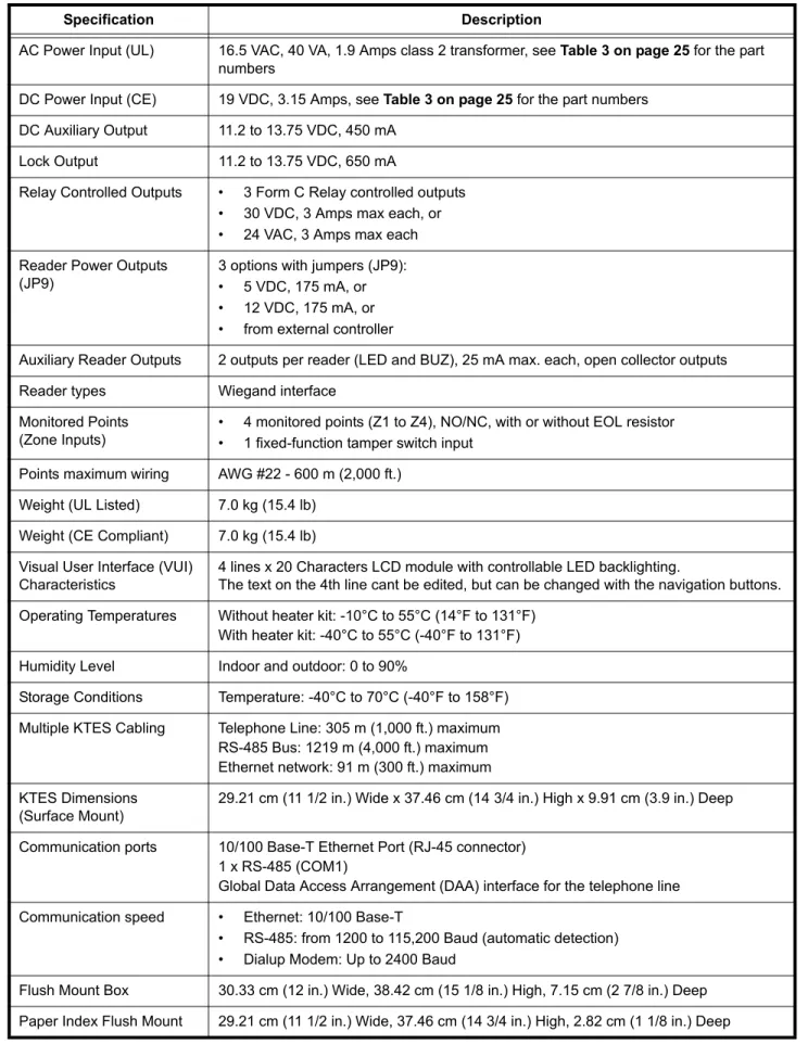
Table 1: Technical Specifications
Specification Description
AC Power Input (UL) 16.5 VAC, 40 VA, 1.9 Amps class 2 transformer, see Table 3 on page 25 for the part numbers
DC Power Input (CE) 19 VDC, 3.15 Amps, see Table 3 on page 25 for the part numbers DC Auxiliary Output 11.2 to 13.75 VDC, 450 mA
Lock Output 11.2 to 13.75 VDC, 650 mA
Relay Controlled Outputs • 3 Form C Relay controlled outputs • 30 VDC, 3 Amps max each, or • 24 VAC, 3 Amps max each Reader Power Outputs
(JP9)
3 options with jumpers (JP9): • 5 VDC, 175 mA, or • 12 VDC, 175 mA, or • from external controller
Auxiliary Reader Outputs 2 outputs per reader (LED and BUZ), 25 mA max. each, open collector outputs Reader types Wiegand interface
Monitored Points (Zone Inputs)
• 4 monitored points (Z1 to Z4), NO/NC, with or without EOL resistor • 1 fixed-function tamper switch input
Points maximum wiring AWG #22 - 600 m (2,000 ft.) Weight (UL Listed) 7.0 kg (15.4 lb)
Weight (CE Compliant) 7.0 kg (15.4 lb) Visual User Interface (VUI)
Characteristics
4 lines x 20 Characters LCD module with controllable LED backlighting.
The text on the 4th line cant be edited, but can be changed with the navigation buttons. Operating Temperatures Without heater kit: -10°C to 55°C (14°F to 131°F)
With heater kit: -40°C to 55°C (-40°F to 131°F) Humidity Level Indoor and outdoor: 0 to 90%
Storage Conditions Temperature: -40°C to 70°C (-40°F to 158°F) Multiple KTES Cabling Telephone Line: 305 m (1,000 ft.) maximum
RS-485 Bus: 1219 m (4,000 ft.) maximum Ethernet network: 91 m (300 ft.) maximum KTES Dimensions
(Surface Mount)
29.21 cm (11 1/2 in.) Wide x 37.46 cm (14 3/4 in.) High x 9.91 cm (3.9 in.) Deep
Communication ports 10/100 Base-T Ethernet Port (RJ-45 connector) 1 x RS-485 (COM1)
Global Data Access Arrangement (DAA) interface for the telephone line Communication speed • Ethernet: 10/100 Base-T
• RS-485: from 1200 to 115,200 Baud (automatic detection) • Dialup Modem: Up to 2400 Baud
Flush Mount Box 30.33 cm (12 in.) Wide, 38.42 cm (15 1/8 in.) High, 7.15 cm (2 7/8 in.) Deep Paper Index Flush Mount 29.21 cm (11 1/2 in.) Wide, 37.46 cm (14 3/4 in.) High, 2.82 cm (1 1/8 in.) Deep
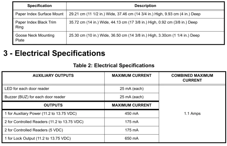
3 - Electrical Specifications
Paper Index Surface Mount 29.21 cm (11 1/2 in.) Wide, 37.46 cm (14 3/4 in.) High, 9.93 cm (4 in.) Deep Paper Index Black Trim
Ring
35.72 cm (14 in.) Wide, 44.13 cm (17 3/8 in.) High, 0.92 cm (3/8 in.) Deep
Goose Neck Mounting Plate
25.30 cm (10 in.) Wide, 36.50 cm (14 3/8 in.) High, 3.30cm (1 1/4 in.) Deep
Table 2: Electrical Specifications
AUXILIARY OUTPUTS MAXIMUM CURRENT COMBINED MAXIMUM
CURRENT
LED for each door reader 25 mA (each)
1.1 Amps Buzzer (BUZ) for each door reader 25 mA (each)
OUTPUTS MAXIMUM CURRENT
1 for Auxiliary Power (11.2 to 13.75 VDC) 450 mA 2 for Controlled Readers (11.2 to 13.75 VDC) 175 mA 2 for Controlled Readers (5 VDC) 175 mA 1 for Lock Output (11.2 to 13.75 VDC) 650 mA
Table 1: Technical Specifications
DN1769-0909 17
4 - Installing the KTES
Important: Make sure that the local telephone company has been notified that you will be installing communication equipment.
4.1 Preparing to Install the KTES
A visual inspection should be made when unpacking the KTES. Any missing item/part or damaged component should be reported immediately.
Stay away from electrical or communication devices
The KTES has been designed to be mounted indoor or outdoor. The cabinet is large enough to accommodate the backup battery and the necessary wiring connections for most applications. Four (4) EMT (Electrical Metallic Tubing) conduit knockouts (1.9 cm (0.75 in)) are provided. The location should be easily accessible for servicing the equipment. The KTES must be located at a minimum distance of 2 m (6 ft) from any high voltage equipment or wiring and from electrical equipment susceptible of generating electrical interference and at a minimum of 8 m (25 ft) from any transmitting equipment.
4.2 Installation
STEP 1: Unpacking the KTES
Check that the following parts are in your KTES package when you unpack it:
• Kantech Telephone Entry System (KTES)
• EntraPass software CD-ROM, version 4.02 or higher
• Installation Manual, English and French version
• Programming Manual, English and French version
Any missing item/part or damaged component should be reported immediately.
Note 1: The 12 VDC backup battery and the ground clamp are not included.
Note 2: Make sure you have adequate sealant (not included).
STEP 2:
Applying Sealant on the Back of the KTESSealant must be applied on each of the four mounting holes when the KTES is installed outside in order to avoid water infiltration. Also, apply sealant around any knockout that will be removed.
Important: Be careful not to apply sealant on the four (4) draining holes at the bottom of the KTES.
Figure 11: Surface Mount Installation
STEP 3: Mounting
It is recommended that you mount the KTES so that the bottom of the enclosure is not higher than 117 cm (46 in.) from the floor. If you install it in a location where there are extremely low temperatures, the outdoor installation might require an optional heater kit in order to meet the environmental conditions.
Caution: Make sure the area stays clear of any objects below the KTES that could interfere with its daily use.
DN1769-0909 19
STEP 4: Connecting the Door Locking Device (DC Powered)
Connecting the Door Lock Device to LK+ and
LK-Check for Local “magnetic lock” Regulations
The door locking device output is controlled according to the end-user programmed parameters for allowing access to or unlocking doors according to schedules and access levels. The door locking device output can operate DC powered locking devices such as an electromechanical strike and can be configured to operate fail-safe or fail-secure (normal or reverse action).
Note: Use 1 K ohm EOL (End-of-Line resistor) between LK+ and LK- terminals if not used.
STEP 5: Connecting the Door Lock Device with an External Power Supply
Use one of the three relay terminals available to connect the door locking device and the external power supply.
STEP 6: Hooking Up Inputs
Connect Devices to Inputs 1 to 4Note: Onboard inputs can be defined with: none, single or double EOL (End-of-Line) resistor(s) according to your settings with the VUI or with EntraPass.
Resistors for all Inputs 5.6K Ohms (EOL or DEOL) (Optional)
The KTES has an on-board capability of monitoring 4 input points. Each onboard input is supervised with or without end-of-line resistors (5.6K ohm). The maximum distance of one line is 600 m (2,000 ft) with AWG #22. Inputs 1-2 are automatically assigned. The door contact is assigned to input 1 and the postal lock is assigned for input 2. There is no obligation to follow these rules but this standard convention facilitates servicing.
DRY (without EOL resistor): In a simple NC dry contact configuration, the secure state is given when a short is detected. The alarm state is given when the input is open. If the alarm switch is programmed as NO device, the
alarm state will be given when the input is shorted.
EOL (with EOL resistor): The secure state is given when a single resistor is detected. The alarm state is given when the input is open or short.
DEOL (Double EOL Resistor): For NC device only, in a DEOL configuration, the secure state is given when a single resistor is detected. The alarm state is given when two resistors in series are detected. The trouble state is given when the input is shorted. The tamper state is given when the input is left open.
STEP 7: Connecting an External Controller
The distance between the reader and the KTES varies by reader type (please consult the installation manual for details).
Important: When you want the external controller to power the reader, the jumper JP9 must be put on external
(EXT) since the external controller will supply the +12 VDC to the reader connected on the READER 1
DN1769-0909 21
STEP 8: Connecting a 3rd Party Controller
The +V terminal voltage level is set by jumper JP9 (5V, 12V or EXT).
STEP 9: Connecting the Telephone Line
Connect the TIP (green) and RING (red) from the Phone Line to the TIP and RING terminals.
Note: The (T-1 and R-1) terminals can be connected to the local telephone.
STEP 10: Connecting the Telephone Line with the Ferrite (KTES-125AUS Model for
Australia and New Zealand only)
Attach the ferrite as close as possible to the TIP and RING terminals.
Connect the TIP and RING from the Phone Line to the TIP and RING terminals.
Tie wrap the cable directly behind the ferrite.
Note: The (T-1 and R-1) terminals can be connected to
the local telephone.
STEP 12: Connecting Multiple KTES on the Same Telephone Line (optional)
It is very important to take into consideration that a maximum of 305 m (1000 ft) should be used between the first KTES and the last KTES, or in total.
STEP 13: Connect the KTES to Earth Ground
Since the KTES uses high performance communication and the telephone line, proper grounding is required to insure safety and proper operation. An AWG #18 single conductor copper wire must be used to ground each KTES to good earth ground as per the local electrical code (be careful with ground loops). The ground clamp should be located below any other ground.
STEP 14: Connect AC Power (North America only)
Power should only be applied to the unit when all connections are completed. Connect the 16VAC terminals to the secondary of the class 2 transformer 120 VAC 60 Hz IN / 16.5 VAC, 40 VA OUT.
DN1769-0909 23
STEP 15: Connect DC Power (EMEA only)
Power should only be applied to the unit when all connections are completed. Connect the +19VDC- terminals to the power supply 19 VDC, 3.15 Amps.
STEP 16: Connecting the Backup Battery
The 12 VDC, 7 A/h backup battery provides operation of up to 12 hours.
Note: The battery must be kept indoor if the outdoor temperature drops below -25
°
C (-13°
F).STEP 17: Connecting the Heater Kit for Outdoor Operation (Optional)
STEP 18: Connecting the Ethernet Cable (Optional)
Connect the Ethernet cable to the RJ-45 port.
• The TXRX (YELLOW) LED is OFF when there is no Ethernet network or the cable is disconnected; FLASHING when there is network activity; and ON when the network is present
• The 100 (GREEN) LED is ON only when the KTES is connected to a 100 Mb/s (100 Base-T) network.
STEP 19: Powering Up the KTES
Once powered, check the blue heartbeat LED status indicator to determine the status of communication and other vital parameters. Refer to the troubleshooting section for the patterns. If the main supply is removed, the 12 VDC, 7 A/h backup battery will support normal operation.
Important: The KTES will not start on backup battery alone.
STEP 20: Programming the KTES
If you intend to program the KTES remotely with an access control software like EntraPass, there are some options that must be done with the VUI before leaving the customer premises.
Enter the KTES programming mode by pressing and holding
¹
during 5 seconds, until you hear a beep. Type in the Installer PIN (8888).Important: For security reasons, keep in mind to change the default installer PIN (8888) after the installation and configuration are completed and give it to the owner or the maintenance dept of the building. Refer to the Tenant Menu in the KTES Programming Manual, DN1770.
Options only Programmable with the VUI
Note: For more information on how to configure the KTES with the VUI, refer to the KTES Programming Manual,
DN1770.
Option Name Keypad Shortcut
Audio Visual > Speaker Volume 8-1-2-2-1 Audio Visual > Microphone Sensitivity 8-1-2-2-2 Audio Visual > Telephone Sensitivity 8-1-2-2-3 Audio Visual > LCD Contrast 8-1-2-2-4 Audio Visual > Live Adjustment 8-1-2-2-5
DN1769-0909 25
5 - KTES Models, Options, Related Documentation and
Miscellaneous Items
Table 3: KTES Models
Part number Description
Models
KTES-125CDN Kantech Telephone Entry System 125 tenants (3000 tenants max, see options), plug-in AC transformer 16 VAC, 40 VA (TR1640P/CSA), KTES EntraPass software (E-KTES-CD1) and accessory kit (KTES-ACC-KIT)
KTES-125US Kantech Telephone Entry System 125 tenants, (3000 tenants max, see options), plug-in AC transformer 16 VAC, 40 VA (TR1640P/UL), KTES EntraPass software (E-KTES-CD1) and accessory kit (KTES-ACC-KIT),
KTES-125EU Kantech Telephone Entry System 125 tenants, (3000 tenants max, see options), switching power supply, AC cord for Europe and UK, KTES EntraPass software (E-KTES-CD1) and accessory kit (KTES-ACC-KIT),
KTES-125AUS Kantech Telephone Entry System 125 tenants, (3000 tenants max, see options), switching power supply, AC cord for Australia, KTES EntraPass software (E-KTES-CD1) and accessory kit (KTES-ACC-KIT-AUS),
Dimensions Drawing
DN1878 KTES Dimensions Drawing
Miscellaneous Items
USB-485 USB-485 interface, USB cable 0.9 m (3 ft) and USB drivers on CD-ROM
VC-485 VC-485 interface, RS-232 cable 3 m (10 ft) with RJ-12 connectors, 740-1012 (DB25F to RJ-12) adaptor, 740-1022 (DB9F to RJ-12) adaptor and 740-1033 (DB25M to RJ-12) adaptor
Optional Accessories
KTES-FBOX Flush mount box with black trim ring
KTES-HEAT Heater pad for temperature below -10°C (14°F)
KTES-INDEX-F Flush mount paper index, black. KTES-INDEX-R trim ring not included KTES-INDEX-R Black trim ring for KTES-INDEX-F flush mount paper index
KTES-INDEX-S Surface mount paper index, black
KTES-MPLATE Goose neck mounting plate with seal, black KTES-CAM-N NTSC color camera with bracket
KTES-CAM-P PAL color camera with bracket KTES-POSTAL Postal lock with bracket
E-KTES-500 Option for a maximum of 500 tenants in total (EntraPass 4.02 required; 1 option per unit) E-KTES-1000 Option for a maximum of 1000 tenants in total (EntraPass 4.02 required; 1 option per unit) E-KTES-3000 Option for a maximum of 3000 tenants in total (EntraPass 4.02 required; 1 option per unit) KTES-ACC-KIT Accessory kit, includes eight (8) 5.6K resistors and one (1) 1K resistor
KTES-PS-NA Power Supply 100V - 240VAC IN / 19 VDC, 3.15 Amps OUT and AC power cord, 3-pin model, for KTES-125CDN and KTES-125US only
KTES-PS-UK Power Supply 100V - 240VAC IN / 19 VDC, 3.15 Amps OUT and AC power cord, for UK only with KTES-125EU
KTES-PS-EU Power Supply 100V - 240VAC IN / 19 VDC, 3.15 Amps OUT and AC power cord, for Europe only with KTES-125EU
KTES-PS-AUS Power Supply 100V - 240VAC IN / 19 VDC, 3.15 Amps OUT and AC power cord, for KTES-125AUS only
TR1640P/UL 16.5 VAC, 40 VA, class 2 transformer for installation in the USA (manufacturer part number Codex model SEP-1640U) TR1640P/CSA 16.5 VAC, 40 VA, class 2 transformer for installation in Canada
(manufacturer part number Codex model SEP/G-1640)
Spare Parts
E-KTES-CD1 EntraPass Special Edition with only KTES-enabled features. Can be upgraded to a full EntraPass Special Edition
KT-TAMPER Tamper switch for cabinet KTES-LOCK Keylock for cabinet with 2 keys KTES-SPEAK Speaker assembly
KTES-LCD LCD module assembly KTES-MPCA Main PCB assembly
KTES-DCPA Door PCB assembly with keypad and microphone KTES-LENS LCD clear lens
DN1769-0909 27
6 - Troubleshooting
Table 4: Reset Types and Descriptions
Table 5: AC and DC Power LED Status Indicators
Jumpers Heartbeat Patterns Resets
Continuous Short Pulses
Soft Reset:
When JP1 and JP2 are ON, the KTES will reset on a) power up, b) pushbutton, or c) EntraPass software 'Manual operator soft reset': • All KTES memory definitions and parameters are verified and
kept intact if still valid.
• The internal event buffer is maintained if still valid. • IP address is kept if valid.
• The KTES generates the appropriate message: a) 'Power ON Soft Reset' b) 'Manual Pushbutton Soft Reset' c) 'Operator Soft Reset'.
3 Long Pulses
Forced Default Static:
When JP1 is ON and JP2 is OFF:
• Same as 'Soft Reset' condition, except IP address is forced to the default static
IP: 192.168.1.2.
4 Short Pulses
Hard Reset:
When JP1 is OFF and JP2 is ON:
• The default installer PIN (8888) is restored. • All KTES memory is settled to default values. • Internal event buffer is cleared.
• IP address is kept if valid.
• KTES generates the message, 'KTES Hard Reset'. • Internal RTC (Real Time Clock) and clock are settled to the
default time and date values January 1st 2009, 00:00:00.
Continuous Long Pulses
Factory Default:
When JP1 and JP2 are OFF:
• The default installer PIN (8888) is restored. • All KTES memory is settled to default values. • Internal event buffer is cleared.
• KTES generates the message 'KTES Factory Default Reset'. • Internal RTC and clock are settled to the default time and date
values January 1st 2009, 00:00:00.
AC Power LED DC Power LED Status Indicators
ON ON
• The AC power or external AC source is present.
• The DC power level is sufficient for all DC operations such as the readers, outputs and the 12V AUX.
OFF ON
• The KTES is running on the 12V rechargable backup battery only. • The DC power supply has been connected with reverse polarity,
7 - Heartbeat Patterns
The KTES status can be obtained from the HEARTBEAT blue LED patterns. It is located near the ribbon cable connected to the door PCB, see Figure 8:. This information is particularly useful when connecting the KTES to the EntraPass system. The following table lists all conditions along with a brief description. Refer to Table 4, if you must reset or change the communication mode with the KTES.
Table 6: Heartbeat Patterns
Booting Up Steady
Factory Default Continuous LONG pulses
Forced Default Static 3 Long Pulses
Modem Initialization Single 2.5 Sec. Burst
Dialup Communication
with EntraPass 2 Short Pulses
Corporate Gateway Communication with
EntraPass
3 Short Pulses
Hard Reset 4 Short Pulses
Fail Soft Continuous Short Pulses
Firmware Update
Quick Pulses 5 pulses per sec. @ 50% duty cycle
Rebooting
Very Quick Pulses 10 pulses per sec. @ 50% duty cycle
DN1769-0909 29
8 - Hardware Default initialization
Note: The Soft Reset and the Hard Reset can be performed directly from the VUI, without having to open the KTES, refer to the KTES Programming Manual, DN1770.
8.1 How to reset the Kantech Telephone Entry System for Factory
Default
Before you start, you must be able to:
• Open the KTES with the key.
• Locate the reset button (SW1) and the two jumpers JP1 - JP2.
• See the flashing blue Heartbeat LED.
1. Remove JP1 and JP2 jumpers as described in Table 4 for Factory Default. 2. Press the reset button.
3. Check the blue Heartbeat LED pattern, wait until the heartbeat pattern corresponds to this:
4. Put back JP1 and JP2 jumpers, close and lock the KTES.
5. Configure the KTES with the VUI, refer to the KTES Programming Manual, DN1770.
Figure 12: KTES Factory Default Steps
9 - Maintenance Recommendations
Important: Only a technician should perform the following maintenance recommendations.
The KTES includes a lithium battery (see the Kantech Telephone Entry System PCB View on page 12). This battery cant be replaced in the field. If the lithium battery stops working, return the circuit board to Kantech. Do not crush, puncture, open, disassemble or otherwise mechanically interfere with the battery. Do not try to recharge the battery. If you need to dispose of the circuit board, wrap it in non-conductive tape.
Regarding the recommended backup battery 12 VDC / 7 Ah: It is the technician’s responsibility to assure that the disposal of used batteries is made according to the waste recovery and recycling regulations applicable to the intended market. Use the recommended battery type ONLY.
Warning: Do not store the batteries in such a way that they come into contact with each other or with any piece of metal. Explosion or fire may occur. Should fire occur, use only dry chemical fire extinguishers. Do not use water to put out the fire. Do not heat the batteries. Do not dispose of the batteries or circuit board in a fire. Do not disassemble the batteries. Do not apply pressure to or deform the batteries. Ensure that the above precautions are strictly observed by related departments, including, but not limited to, production, sales and outside contractors.
It is highly recommended to test the KTES by performing the following tests: 1. Bi-annual test for backup battery:
Remove AC power (UL Listed) or DC power (CE Compliant) from the KTES and let it work on backup battery power for one hour. This test will ensure that in the event of a power failure, the backup battery will be able to support normal operations. This test should be performed twice a year. Once the test has been performed successfully, reconnect power to the KTES.
2. Annual test for lithium battery:
Measure voltage when power is totally removed from the KTES (AC or DC and backup battery power). To ensure maximum operation and to prevent loss of the database, contact your distributor to return the KTES for maintenance, if the lithium battery voltage measures below 2.5 VDC.
DN1769-0909 31
Appendix A - Installation Checklist
The following checklist enumerates the steps to install the system.
Installation Steps Pages
STEP 1: Unpacking the KTES see page 17
STEP 2: Applying Sealant on the Back of the KTES see page 17
STEP 3: Mounting see page 18
STEP 4: Connecting the Door Locking Device (DC Powered) see page 19
STEP 5: Connecting the Door Lock Device with an External Power Supply see page 19
STEP 6: Hooking Up Inputs see page 19
STEP 7: Connecting an External Controller see page 20
STEP 8: Connecting a 3rd Party Controller see page 21
STEP 9: Connecting the Telephone Line see page 21
STEP 10: Connecting the Telephone Line with the Ferrite (KTES-125AUS Model for
Australia and New Zealand only) see page 21
STEP 11: Connecting the RS-485 (optional) see page 21
STEP 12: Connecting Multiple KTES on the Same Telephone Line (optional) see page 22
STEP 13: Connect the KTES to Earth Ground see page 22
STEP 14: Connect AC Power (North America only) see page 22
STEP 15: Connect DC Power (EMEA only) see page 23
STEP 16: Connecting the Backup Battery see page 23
STEP 17: Connecting the Heater Kit for Outdoor Operation (Optional) see page 23
STEP 18: Connecting the Ethernet Cable (Optional) see page 24
STEP 19: Powering Up the KTES see page 24
Copyright © 2009 Tyco International Ltd. and its Respective Companies. All Rights Reserved.