c
Sharif University of Technology, August 2010
Eect of Internal and External Shear Wall
Location on Strengthening Weak RC Frames
M.Y. Kaltakci
1, M.H. Arslan
1;and G. Yavuz
1Abstract. Hundreds of thousands of Reinforced Concrete (RC) buildings have been either seriously damaged or have completely collapsed due to major earthquakes in recent years in Turkey, therefore, the construction of RC buildings gained momentum by the aid of scientic studies on strengthening. As well as mentioning the importance of the strengthening process using Shear Walls (SW) in RC buildings of poor earthquake performance, an experimental study carried out to analyze the inuence of the location of a SW on the existing system was also mentioned in this study. A total of three, two-storey, two-bay RC frames of 1/3 scale were produced for the experiments by expecting them to represent the behavior of the RC frames having weak earthquake strength; two of which were strengthened with SWs. The main aim of this study is to compare the eectiveness of internal and external SW locations on strengthened weak, RC frame earthquake behavior. The strength, stiness and ductility of the tested frames were compared within the light of numerical results obtained from the experiments. In the study, an overall comparison of strengthening methods was made in terms of applicability, usability and cost.
Keywords: Experimental study; Reinforced concrete; Shear wall; Strengthening; Earthquake damage; Pushover
INTRODUCTION
Many existing Reinforced Concrete (RC) buildings in Turkey and similar countries are far from providing the parameters of adequate stiness, strength and ductility, which are of great importance for earthquake engineering. Particularly, in Turkey, nearly 500.000 buildings have entirely collapsed in the last century [1] because of earthquakes. The majority of the collapsed and damaged buildings are composed of RC buildings. Reasons regarding the fact that RC buildings are so damaged can be listed as poor concrete quality (1012 MPa), lack of an adequate connement reinforcement on column-beam joints and connement points, lengths of reinforcement overlapping being inadequate in pro-portion to the lengths of columns between the stories, and inadequate stiness due to too small column sections. Moreover, examinations carried out in these regions subsequent to earthquakes [2-4] have revealed that Shear Walls (SWs) were not used in most of
1. Faculty of Engineering and Architecture, Department of Civil Engineering, Selcuk University, Konya, Turkey.
*. Corresponding author. E-mail: [email protected] Received 9 January 2010; received in revised form 9 March 2010; accepted 18 May 2010
the RC buildings that had collapsed or were severely damaged.
Major earthquakes, beginning with the 1992 Erz-incan earthquake (7:2Mw), such as the August 1999
Marmara earthquake (7:4Mw) and the November 1999
Duzce earthquake (7:3Mw), put forth the necessity for
examining and strengthening many existing buildings, including, particularly, public buildings. Both the Turkish Government and other major institutions, such as the World Bank and the European Union, have begun to allocate sucient funding related to this issue. Research has shown that the most eective and economic method of increasing the stiness and lateral-load strength of existing buildings is adding new ele-ments to the current building system [5-8]. It is known that the bearing system can attain adequate stiness and strength levels through strengthening by adding a SW to the existing construction system [9-12]. The selection of especially the location and amount of SWs is of utmost importance in strengthening, which can be accomplished by adding a SW so as not to exert further pressure on the existing RC system that is already weak.
Strengthening SWs may come out in various positions according to their positions in the plan. The method of lling the gaps between columns of the
Eect of Shear Wall Location 313 bearing system with complete or partial SWs is dened
as the interior SW. However, the method of lling, especially the frame gaps, with SW has some archi-tectural and applicability diculties. System strength-ening performed by lling the frame gaps fully with SW mostly causes an architectural function change and accordingly the alteration of the interior SW gives rise to serious economic loss. On the other hand, in the application of partial interior SW changes occurring in use can be partially lessened considering the gaps that necessitate lling as per their usage aims [13]. The most signicant disadvantage of the method of strengthening with interior SW is that crucial problems arise in especially widely used public buildings, such as schools and hospitals, since the strengthened building cannot be used for a long time. Being motivated by this problem, research has been carried out with the supposition that shifting the location of the SW from the interior to the exterior of the building is a rapidly and easily applicable strengthening method especially in public buildings [14]. The most important disadvantage of strengthening with exterior SW is the need for a large area for the change in use of the exterior front and the ground of the exterior SW.
The primary problem in strengthening the exist-ing RC buildexist-ings with SW, which are dened as de-cient against earthquake, is determining the location of the SW. The location of SW is of primary importance in many respects, such as structural performance, ap-plicability, reassessment in utilization process, economy and environmental conditions.
In this study, the results of the experimental part were carried out to examine, comparatively, the inuence of the eectiveness of internal and external SW locations on the existing systems in frames with a low capacity of horizontal load bearing, being analyzed within an overall point of view. A total of three RC frames, which represent the behavior of weak RC frames, were produced; two of them subjected to SW strengthening. The capacities of strength, stiness and ductility of the systems were compared within the light of the numerical results obtained from the experiments. Also, an overall comparison of both strengthening methods was made as per applicability, usability and cost. As a result of all these evaluations, a general opinion was obtained regarding the RC frames. EXPERIMENTAL STUDY
Properties of Test Specimens
In this section, the material and section properties of tested frames, the test set-up and the locations of transducers are presented. In the experimental phase, three 2-bay, 2-story, 1/3 scaled RC frames having non-seismic detailing were tested under reversed-cyclic
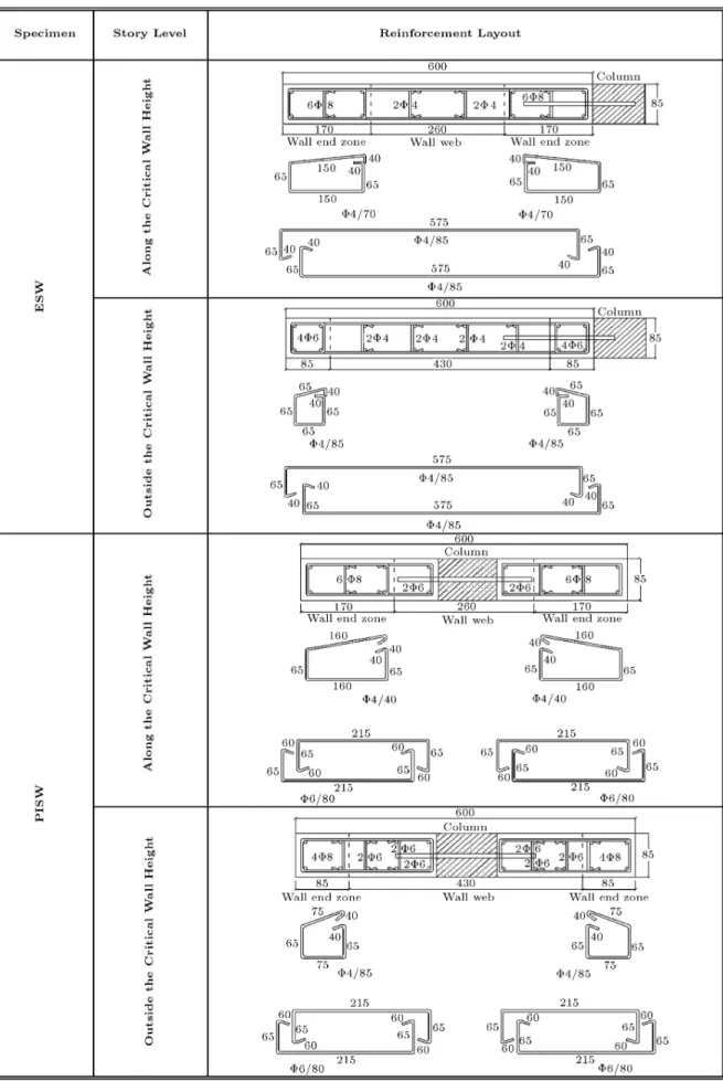
lat-eral load simulating an earthquake eect. These frames have deciencies commonly observed in Turkey, such as low concrete compression strength, inadequate lateral stiness, inadequate connement, lapped splices at oor levels and the use of plain bars. The geometrical dimensions and reinforcement details of test specimens are given in Figure 1.
In the reinforcement detailing of the frames, general rules of the TEC-75 [15] were selected. Since a 1/3 geometric scale was considered in this study, the modeling was performed by reducing all the di-mensional values of the reinforced concrete frame with respect to this scale. The sizes of the aggregates and the longitudinal and transverse reinforcements were approximately reduced considering the ratio of 1/3. In all columns, plain bars of 8 mm diameter were used as the longitudinal reinforcement, and the longitudinal reinforcement ratios were approximately selected as 2% for all columns. In all beams, longitudinal and bended plain bars of 6 mm diameter, commonly used in Turkey, were used as beam reinforcements. In all beams and columns, stirrups of 4 mm diameter were used with respect to the scale factor by placing them at each 100 mm. The ends of these ties had 90 hooks to
represent the common application in Turkey, despite the fact that the requirement of using 135 hooks
for stirrups was emphasized in TEC-2007 [16]. The longitudinal reinforcements of columns were spliced at oor and foundation levels.
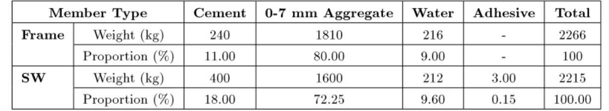
During the last earthquakes, the concrete com-pression strength was observed between 8-15 MPa in Turkey. In the frames, the target cylinder concrete compression strength was selected as 12 MPa to rep-resent the average Turkish RC building construction stock. According to TBC-500-2000 [17], the compres-sion strength of concrete was determined by taking the average of three cylindrical concrete specimens for one frame. In Table 1, the concrete mixture proportions
Figure 1. The dimensions of unstrengthened test specimens.
Table 1. Mixture proportion for test frames (weight for 1 m3of concrete).
Member Type Cement 0-7 mm Aggregate Water Adhesive Total Frame Weight (kg) 240 1810 216 - 2266
Proportion (%) 11.00 80.00 9.00 - 100 SW Weight (kg) 400 1600 212 3.00 2215
Proportion (%) 18.00 72.25 9.60 0.15 100.00
of tested frames are presented. Materials used in this mixture are given by weight for 1 m3 concrete. The
average concrete compression strengths, yielding and ultimate strength values of reinforcements used in these specimens are listed in Table 2.
The RC SWs were designed according to TEC-2007 rules. The minimum aspect ratio of the shear wall is given as 7 in TEC-2007. According to the rule, the height and width of the SWs are 600 and 85 mm, respectively. The longitudinal reinforcements and the lateral reinforcement of the SW were selected as 8 mm and 4 mm, respectively, as deformed bars in both shear walls. The SW details are given in Figure 2 for both types. The anchorage bars were selected as 8 mm diameter and spaced at 150 mm, as for deformed bars in both shear walls too. The locations of anchorage bars are shown in Figure 3. The target concrete quality of SW is intended as C30 (compression strength is 30 MPa). The minimum compression strength should be 20 MPa, according to TEC-2007. In Table 1, the concrete mixture proportions of shear walls are presented. The average concrete compression strengths, yielding and ultimate strength values of reinforcements used in these specimens are also listed in Table 2. It must be noted that to obtain low
concrete compressive strength for the unstrengthened frames, which reect most existing RC buildings that were constructed before 1998 in Turkey, high water cement (W=C) ratio was selected. On the contrary, the SWs constructed in accordance with the rules of TEC-2007, the minimum compressive strength of the concrete should be larger than 20 MPa. For this reason, the W/C ratio was approximately selected as 0.45. Test Device
The testing system consisted of a strong oor, a steel reaction wall, loading equipment and an instrumenta-tion and data acquisiinstrumenta-tion system (Figure 4). The foun-dations of specimens were xed to the strong oor with high-strength steel bolts and then the displacement transducers were installed on the frames as shown in Figure 5. The specimens were tested under a reversed-cyclic lateral load that simulates the earthquake eect. The lateral load was applied on the top story using a hydraulic jack to measure the magnitude of this load (base shear force) and transmitted to other side of frames by means of special transmission bolts. A steel stability frame was constructed around the test specimens to prevent out-of-plane displacements. The
Table 2. General properties of the specimens.
Axial Load Concrete (MPa) Reinforcement Bars (MPa) (fy=fsu)
Specimen Frame Type Level on Frame SW a Column Frame SW Plain Deformed
(N0=Nr) 4 6 8 6 8
B 0:1 0:2 14.05 |- 335
469 450555 375490 | |
ESW 0:1 0:2 13.30 29.00 335
469 450555 375490 570710 610750
PISW 0:1 0:2 14.24 30.24 335
Eect of Shear Wall Location 315
Figure 3. The locations of anchorage bars.
Figure 4. Test set-up and loading system.
applied lateral load was measured using a compression-tension load cell of 500 kN capacity. The lateral displacements of the test specimens at each oor level were measured by displacement transducers (LVDT). The lateral loading program was applied as load-controlled up to yielding and displacement-load-controlled
after yielding. The axial load applied on each column prior to the application of the lateral load was measured by one directional load cell of 200 kN capacity and controlled continuously. In order to simulate the real condition, axial loads were applied on columns by steel cables about 0:10Acfc load level.
Eect of Shear Wall Location 317
Figure 5. The location of displacement transducers.
Behaviors of Specimens and Test Results General Behavior
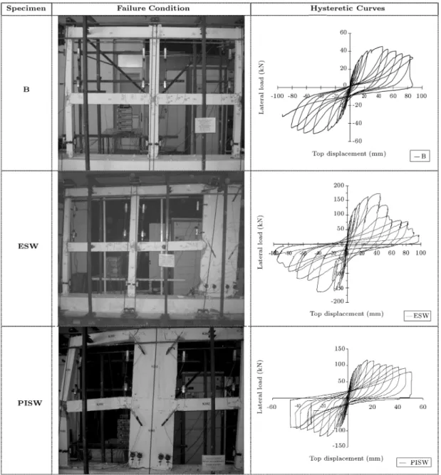
Failure modes of frames were observed as exural for all specimens. The measured lateral loads and displacements under rst cracking, yielding, maximum load and failure condition were presented in Table 3 for all specimens. In this table, the failure load was accepted as 85% of the measured maximum lateral load (P85, 85).
For specimen B (Bare/Unstrengthened frame), the rst vertical crack on beams occurred at the changing region of the bended bars. In following cycles, horizontal and diagonal cracks occurred in the rst story left column-to-beam connection. After the cracking of column bases, new cracks developed rapidly and the slope of the lateral load-displacement curve
began to decrease. At this stage, the loading type was displacement-controlled as shown in Table 3. Shear failures were observed on exterior column-beam joints due to the lack of connement, and the exural failure occurred in the changing region of the bended bar of the beam. The rst plastic hinge occurred in the right exterior column base. A general view of the specimen at the failure load level is given in Figure 6.
In specimens ESW (External Shear Walled) and PISW (Partial Inlled Shear Walled), there were no important cracks observed up to the displacement-controlled loading, except for hair cracks occurred on the beams. After the maximum lateral load level, horizontal exural cracks developed at the base of SWs. In the last cycles, the longitudinal reinforcement of the column buckled and the concrete cover crushed due to the reinforcement hook at the side joints of
Table 3. Important measured values during the test.
Load Controlled Displacement Controlled Specimen Loading First Cracking Yielding Load Maximum Load Failure
Direction Load Top Disp. Load Top Disp. Load Top Disp. Load Top Disp. (kN) (mm) (kN) (mm) (kN) (mm) (kN) (mm) B Forward 15.05 2.25 20.00 3.50 48.48 43.51 36.36 63.29
Backward -15.29 -2.14 -20.00 -3.20 -49.05 -49.58 -42.14 -74.55 ESW Forward 59.69 3.11 128.11 12.29 170.92 42.75 145.28 49.05
Backward -59.45 -2.81 -135.18 -12.23 -161.64 -41.41 -137.39 -48.71 PISW Forward 31.82 1.34 100.39 9.96 116.67 18.12 99.17 35.71
Figure 6. The general aspects of specimens.
ESW specimen. In PISW, diagonal cracks occurred at the left exterior joint of the rst story. In both strengthened frames, there was no rotation measured in the SW foundation. The addition of SWs and frames showed monolithic behavior with columns during the test. The general view of the specimens and hysteretic curves are also given in Figure 6.
Test Results
Response envelope curves (load-displacement curves) of the strengthened specimens are given in Figure 7, together with the response envelope curve of the bare frame. These curves were plotted by connecting the peak points of these hysteretic curves for each specimen, which show the strength and stiness
Eect of Shear Wall Location 319 is seen that PISW had strength and an initial stiness
close to that of ESW for each loading direction oc-curred. A comparison of the behavior of test specimens was made in terms of lateral strength and stiness. The test results are presented in Table 4.
After the strengthening operation, the average lateral load bearing capacities of the strengthened frames, respectively, increased 3.4 times and 2.4 times in PISW and ESW according to the B (as shown in Table 4).
In this study, only the plane behavior of the tested frames was investigated. Therefore, the spe-cial arrangements, as mentioned above, were used to prevent an out-of-plane eect. However, there was no out-of-plane action observed in all frames [13,18,19]. Moreover, no compression failure occurred in any column due to low axial load level.
ANALYTICAL STUDY
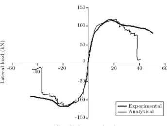
In this part of the study, the load-displacement curves obtained experimentally were compared with the ana-lytical results of nonlinear static analysis (static push-over analysis) executed by the SAP2000 [20] software program. Pushover analyses simulated the nonlinear lateral load-displacement relationship of the test speci-mens analytically. The popularity of pushover analysis is due to its ability to estimate load-displacement values with great accuracy without applying any cycling loading. In the literature, there are various methods on nonlinear cycling analyses of RC frames [21,22]. Lateral load-upper story displacement diagrams of the experiments are compared with the obtained results and presented in Figures 8 to 10. The lateral load capacities of the specimens were simulated with great success by using the SAP2000 computer program. INFLUENCE OF THE LOCATION OF SHEAR WALL ON USE OF BUILDING During the operation of strengthening using SW, which is widely used in making the weak RC frames safe against earthquake, the location of the SWs is an
Figure 8. Comparison of the experimental and analytical curves of the frame B.
Figure 9. Comparison of experimental and analytical curves of frame PISW.
arguable point, particularly in terms of the architecture of the building. Parameters, such as strength, stiness, and ductility, which were introduced to the building by the strengthening element, changed the strengthening created in the building plan. User satisfaction and the changing function of the building are also the other parameters to be taken into consideration. Moreover, in addition to the preferred strengthening method, the
Table 4. Comparison of the test results.
Characteristics B PISW ESW PISW/B ESW/B ESW/PISW Max. Base Shear
(forward) kN 48.48 116.67 170.92 2.41 3.52 1.46 Max. Base Shear
(backward) kN -49.05 117.17 -161.64 2.39 3.29 1.38 Initial Stiness
kN/mm 5.90 84.70 41.37 14.36 7.01 2.05 Maximum Load
Figure 10. Comparison of the experimental and analytical curves of the frame ESW.
extra cost of alteration that either the strengthening element or the strengthening operation creates at the interior or exterior of the building, is another important factor in selecting the location of the SWs.
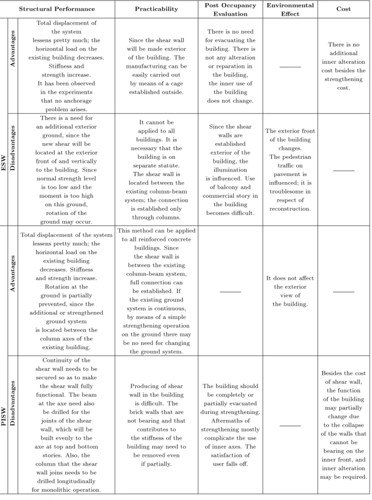
Comparisons of these strengthening methods, the experimental ndings of which have been presented previously, were carried out not only in terms of their contributions to the building performance, but also in architectural, applicability and economic criteria, and shown in Table 5. The strengthening methods are assessed in two separate groups, with respect to the advantages and disadvantages in the table given. RESULTS AND DISCUSSION
By virtue of the observations and examinations carried out during the study, it is estimated that many existing RC buildings will exhibit poor performance in case of a possible dynamic inuence in Turkey. Within the light of this estimation, the buildings should necessary be strengthened, so as to increase their safety against any possible earthquake eect. In this study, an experi-mental study dealing with a widely used strengthening method in Turkey, by using SWs, was carried out for which the location of the SW was selected as the basic parameter of the analysis. In the light of the scaled experimental elements and the data obtained from the experiments, it is concluded that:
A signicant increase was provided for the capacity of the horizontal load bearing and stiness of the existing weak frame during the application of each strengthening method.
Shear walls and frame columns worked monolith-ically in both applications, and any anchorage debonding was not seen at the column-shear joint. Although the ESW type was expected to display a
higher horizontal load bearing capacity than that of
the PISW type, the PISW type presented higher horizontal load bearing and lower horizontal dis-placement with respect to the ESW type, during the tests.
During the application of the ESW type, the existing column contributed to the performance, since it was located at the end point, and the SW worked mono-lithically with the exterior column of the frame. In both strengthening methods, any serious damage
was not observed on the frame elements until the maximum horizontal load level was reached. It was proved that the bended bars, widely used as
beam reinforcements in Turkey, could not prevent the failure of the beam and became ineective under cycling loads, such as earthquakes.
It must be noted that according to relative ex-periments, the axial loading of the columns was low (0:10Acfc), therefore, the test results are not
credible for multi-storey frames.
The objective of the paper was to observe the general behavior of the frame systems under lateral loading, simulating earthquake eects. As a result, the behavioral changes between the strengthened and unstrengthened frames can be easily compared by the help of the data obtained by this study. In the meantime, the frames are tested under quasi static loading. However, the real seismic behavior of the frames can be observed only under shaking table tests or pseudo dynamic tests. Therefore, it can be stated that the results of the study do not completely represent the real status.
The issue of the location of the added new RC SW has maximum meaning in spatial asymmetric multi-storey buildings. For this reason, the eect of SW location should be researched for asymmetric multi-storey buildings under real loading conditions, such as a shaking table.
The most important parameter that should be considered during the strengthening process of a RC building was the performance of the building against earthquake eects. On the other hand, the archi-tectural function and environmental condition of the building should also be evaluated extensively. Addi-tionally, the cost analysis for the strengthening process of the building should be another signicant factor during the analyses. According to the considerations within the light of these criteria, if the buildings are not adjacent to one another and extensively used (public buildings such as schools and hospitals) without any commercial story and constructional overhangs, such as balconies and consoles, the application of exterior SW can be recommended. Even though it can be applied to a limited number of buildings, the greatest
Eect of Shear Wall Location 321
Table 5. Summary of the eect of SW type upon dierent criteria.
Structural Performance Practicability Post Occupancy Evaluation Environmental Eect Cost Adv an tages
Total displacement of the system lessens pretty much; the
horizontal load on the existing building decreases.
Stiness and strength increase. It has been observed
in the experiments that no anchorage problem arises.
Since the shear wall will be made exterior
of the building. The manufacturing can be
easily carried out by means of a cage established outside.
There is no need for evacuating the building. There is not any alteration or reparation in
the building, the inner use of
the building does not change.
There is no additional inner alteration cost besides the strengthening
cost.
ESW Disadv
an
tages
There is a need for an additional exterior
ground, since the new shear will be located at the exterior
front of and vertically to the building. Since normal strength level is too low and the moment is too high
on this ground, rotation of the ground may occur.
It cannot be applied to all buildings. It is necessary that the
building is on separate statute. The shear wall is located between the existing column-beam system; the connection
is established only through columns.
Since the shear walls are established exterior of the
building, the illumination is inuenced. Use
of balcony and commercial story in
the building becomes dicult.
The exterior front of the building
changes. The pedestrian
trac on pavement is inuenced; it is troublesome in respect of reconstruction. Adv an tages
Total displacement of the system lessens pretty much; the
horizontal load on the existing building decreases. Stiness and strength increase.
Rotation at the ground is partially prevented, since the additional or strengthened
ground system is located between the
column axes of the existing building.
This method can be applied to all reinforced concrete
buildings. Since the shear wall is between the existing column-beam system,
full connection can be established. If the existing ground system is continuous, by means of a simple strengthening operation on the ground there may
be no need for changing the ground system.
It does not aect the exterior view of the building. PISW Disadv an tages
Continuity of the shear wall needs to be secured so as to make the shear wall fully functional. The beam
at the axe need also be drilled for the joints of the shear wall, which will be built evenly to the axe at top and bottom
stories. Also, the column that the shear wall joins needs to be drilled longitudinally for monolithic operation.
Producing of shear wall in the building is dicult. The brick walls that are not bearing and that
contributes to the stiness of the building may need to
be removed even if partially.
The building should be completely or partially evacuated during strengthening.
Aftermaths of strengthening mostly
complicate the use of inner axes. The satisfaction of
user falls o.
Besides the cost of shear wall,
the function of the building
may partially change due to the collapse of the walls that
cannot be bearing on the inner front, and inner alteration may be required.
advantage of the application of exterior SW is the fact that there is no need for the user to evacuate the building during the strengthening process and an additional alteration is not required inside the building. On the other hand, though the interior shear wall can be applied commonly to all kinds of buildings, the user has to evacuate the building during the strengthening process and post-strengthening additional reparation and, therefore, alteration costs arise. In earthquake-prone countries and regions, such as Turkey, where most of the building stock is composed of RC buildings with poor earthquake strength, the mentioned build-ings should be urgently strengthened by considering the conditions, importance and architecture of the building so as to prevent further losses.
ACKNOWLEDGMENT
This study was supported nancially by S.U. - BAP (018-2002 and 143-2004). The authors also thank Prof. Dr. E. Atmtay (METU) for his valuable assistance. NOMENCLATURE
Ac gross sectional area of concrete
B unstrengthened frame
ESW External Shear Wall
fc concrete compressive strength
fsu ultimate strength of reinforcement bar fy yielding strength of reinforcement bar LVDT Linear Variable Displacement
Transducer No applied axial force
Nr axial force carrying capacity
P85 %85 of measured maximum lateral
load
PISW Partially Inlled Shear Wall
RC Reinforced Concrete
SW Shear Wall
85 displacement value corresponding to
85% of measured maximum lateral load, P85
diameter of plain reinforcement bar
diameter of deformed reinforcement
bar REFERENCES
1. Cagatay, I. \Experimental evaluation of buildings damaged in recent earthquakes in Turkey", Engineer-ing Failure Analysis, 12, pp. 440-452 (2005).
2. Arslan, M.H. and Korkmaz, H.H. \What is to be learned from damage and failure of reinforced concrete
structures during recent earthquakes in Turkey?", Engineering Failure Analysis, 14, pp. 1-22 (2007). 3. Sezen, H. et al. \Performance of reinforced concrete
buildings during the August 17, 1999 Kocaeli, Turkey Earthquake, and the seismic design and construction practice in Turkey", Engineering Structures, 25, pp. 103-114 (2003).
4. Bruneau, M. \Building damage from the Marmara, Turkey Earthquake of August, 1999", Journal of Seis-mology, 6, pp. 357-377 (2002).
5. Higashi, Y. and Kokusho, S., \The strengthening method of existing reinforced concrete buildings", US-Japan Cooperative Research Program in Earthquake Engineering, Honolulu HI (1975).
6. Ayala, D.D. and Charleson, A.W. \Review of seismic strengthening guidelines for reinforced concrete build-ings in developing countries", 12th European Earth-quake Engineering Conference, London, pp. 820-831 (2004).
7. Ersoy, U. \Seismic rehabilitation-application, research and current needs", Paper No. 2099, Proceedings of the 11th World Conference on Earthquake Engineering, Acupulco, Mexico (1996).
8. Wyllie, L.A. \Strengthening strategies for improved seismic performance", Paper No. 1424, Proceedings of the 11th World Conference on Earthquake Engineer-ing, Acupulco, Mexico (1996).
9. Canbay, E. et al. \Contribution of RC inlls to seismic behavior of structural systems", ACI Structural Jour-nal, 100, pp. 637-643 (2003).
10. Celep, Z. and Ozer, E. \Post-earthquake rehabil-itation of moderately damaged reinforced concrete structures", in Proc. Second Japan-Turkey Workshop on Earthquake Engineering, 1, pp. 61-72 (1998). 11. Sonuvar, M. et al. \Rehabilitation of RC frames with
RC inlls", ACI Structural Journal, 101, pp. 494-501 (2004).
12. Phan, L.T. et al. \Strengthening methodology for lightly reinforced concrete frames: Recommended de-sign guidelines for strengthening with inll walls", Building and Fire Research Laboratory National Insti-tute of Standards and Technology, Gaithersburg, MD 20899, NISTIR 5682 (July 1995).
13. Yavuz, G. \The seismic behaviour of non-ductile re-inforced concrete frames having poor seismic perfor-mance with partially reinforced concrete shear walls", PhD Thesis, Selcuk University, Konya, Turkey (2005). 14. Kaltakci, M.Y. et al. \A new approach on the strength-ening of primary school buildings in Turkey: An application of external shear wall", Building and En-vironment, 43, pp. 983-990 (2008).
15. TEC-75, \Turkish earthquake code", Regulations on Structures Constructed in Disaster Regions, Ministry of Public Works and Settlement, Ankara, Turkey (1975).
Eect of Shear Wall Location 323
16. TEC-2007 \Turkish earthquake code", Regulations on Structures Constructed in Disaster Regions, Ministry of Public Works and Settlement, Ankara (2007). 17. TBC-500-2000 \Requirements for design and
con-struction of reinforced concrete structures", Ankara, Turkish Standards Institute (2000).
18. Arslan, M.H. \Strengthening non-ductile reinforced concrete frames by columns failure in tension by appending external shear wall", PhD Thesis, Selcuk University, Konya, Turkey (2007).
19. Kaltakci, M.Y. et al. \The eect of column cross section to frame ductility in RC frames having poor seismic performance", Journal of Engineering and Applied Sciences, 2(10), pp. 1524-1532 (2007). 20. CSI. SAP2000 V-7.4. Integrated nite element analysis
and design of structures basic analysis reference man-ual. Berkeley (CA. USA): Computers and Structures Inc. (2000).
21. Hashemi, S.SH. et al. \Nonlinear cyclic analysis of re-inforced concrete frames, utilizing new joint element", Scientia Iranica, Transaction A, 16(5), pp. 490-501 (2009).
22. Nazem, M. et al. \Nonlinear FE analysis of reinforced concrete structures nonlinear FE analysis of reinforced concrete structures using a Tresca-type yield surface", Scientia Iranica, Transaction A, 16(5), pp. 512-519 (2009).
BIOGRAPHIES
Mevlut Yasar Kaltakci is a Professor at Selcuk University, Konya, Turkey. He received his BS degree from Selcuk University, his MS degree from Anadolu University, Eskisehir, Turkey, and his PhD from Selcuk University in 1980, 1983 and 1990, respectively. His research interests include: Seismic Design of Rein-forced Concrete Structures, Repair and Strengthening of Buildings.
Musa Hakan Arslan is an Assistant Professor at Selcuk University, Konya, Turkey. He received his BS and MS degrees from Istanbul Technical University and his PhD from Selcuk University in 1998, 2000 and 2007, respectively. His research interests include: Performance Based Analysis, Prefabricated Structures, Design of Strengthened Reinforced Concrete Struc-tures, and Articial Neural Network.
Gunnur Yavuz is an Assistant Professor at Selcuk University, Konya, Turkey. She received her BS and MS degrees from Selcuk University and her PhD from Selcuk University in 1996, 1999 and 2005, respectively. Her research interests include: Design of Strengthened Reinforced Concrete Structures, Steel and Composite Structures.