Cisco UCS Common Platform Architecture Version 2
(CPAv2) for Big Data with Cloudera
Building a 64 Node Hadoop Cluster
Last Updated: February 25, 2015
Cisco Validated Design 2
About Cisco Validated Design (CVD) Program
The CVD program consists of systems and solutions designed, tested, and documented to facilitate faster, more reliable, and more predictable customer deployments. For more information visit
http://www.cisco.com/go/designzone.
ALL DESIGNS, SPECIFICATIONS, STATEMENTS, INFORMATION, AND RECOMMENDATIONS (COLLEC-TIVELY, "DESIGNS") IN THIS MANUAL ARE PRESENTED "AS IS," WITH ALL FAULTS. CISCO AND ITS SUPPLIERS DISCLAIM ALL WARRANTIES, INCLUDING, WITHOUT LIMITATION, THE WARRANTY OF MERCHANTABILITY, FITNESS FOR A PARTICULAR PURPOSE AND NONINFRINGEMENT OR ARISING FROM A COURSE OF DEALING, USAGE, OR TRADE PRACTICE. IN NO EVENT SHALL CISCO OR ITS SUP-PLIERS BE LIABLE FOR ANY INDIRECT, SPECIAL, CONSEQUENTIAL, OR INCIDENTAL DAMAGES, INCLUDING, WITHOUT LIMITATION, LOST PROFITS OR LOSS OR DAMAGE TO DATA ARISING OUT OF THE USE OR INABILITY TO USE THE DESIGNS, EVEN IF CISCO OR ITS SUPPLIERS HAVE BEEN ADVISED OF THE POSSIBILITY OF SUCH DAMAGES.
THE DESIGNS ARE SUBJECT TO CHANGE WITHOUT NOTICE. USERS ARE SOLELY RESPONSIBLE FOR THEIR APPLICATION OF THE DESIGNS. THE DESIGNS DO NOT CONSTITUTE THE TECHNICAL OR OTHER PROFESSIONAL ADVICE OF CISCO, ITS SUPPLIERS OR PARTNERS. USERS SHOULD CONSULT THEIR OWN TECHNICAL ADVISORS BEFORE IMPLEMENTING THE DESIGNS. RESULTS MAY VARY DEPENDING ON FACTORS NOT TESTED BY CISCO.
CCDE, CCENT, Cisco Eos, Cisco Lumin, Cisco Nexus, Cisco StadiumVision, Cisco TelePresence, Cisco WebEx, the Cisco logo, DCE, and Welcome to the Human Network are trademarks; Changing the Way We Work, Live, Play, and Learn and Cisco Store are service marks; and Access Registrar, Aironet, AsyncOS, Bringing the Meeting To You, Cata-lyst, CCDA, CCDP, CCIE, CCIP, CCNA, CCNP, CCSP, CCVP, Cisco, the Cisco Certified Internetwork Expert logo, Cisco IOS, Cisco Press, Cisco Systems, Cisco Systems Capital, the Cisco Systems logo, Cisco Unity, Collaboration Without Limitation, EtherFast, EtherSwitch, Event Center, Fast Step, Follow Me Browsing, FormShare, GigaDrive, HomeLink, Internet Quotient, IOS, iPhone, iQuick Study, IronPort, the IronPort logo, LightStream, Linksys, Media-Tone, MeetingPlace, MeetingPlace Chime Sound, MGX, Networkers, Networking Academy, Network Registrar, PCNow, PIX, PowerPanels, ProConnect, ScriptShare, SenderBase, SMARTnet, Spectrum Expert, StackWise, The Fast-est Way to Increase Your Internet Quotient, TransPath, WebEx, and the WebEx logo are registered trademarks of Cisco Systems, Inc. and/or its affiliates in the United States and certain other countries.
All other trademarks mentioned in this document or website are the property of their respective owners. The use of the word partner does not imply a partnership relationship between Cisco and any other company. (0809R)
4
About Cisco Validated Design (CVD) Program
About the Authors
Raghunath Nambiar, Cisco Systems
Raghunath Nambiar is a Distinguished Engineer at Cisco's Data Center Business Group. His current responsibilities include emerging technologies and big data strategy.
Manankumar Trivedi, Cisco Systems
Manankumar Trivedi is a Performance Engineer in the Data Center Solutions Group at Cisco Systems. He is part of solution engineering team focusing on big data infrastructure and performance. He holds masters of Science degree from Stratford University.
Karthik Kulkarni, Cisco Systems
Karthik Kulkarni is a Technical Marketing Engineer in the Data Center Solutions Group at Cisco Systems. He is part of solution engineering team focusing on big data infrastructure and performance.
Jeff Bean, Cloudera
Jeff Bean has been at Cloudera since 2010. He has helped several of Cloudera's most important customers and partners with their adoption of Hadoop and HBase, including cluster sizing, deployment, operations, application design, and optimization.
Jeff currently is a partner engineer at Cloudera, where he handles field support, certifications, and joint engagements with partners. With the release of Cloudera 5, Jeff has assisted many partners migrate to YARN.
Acknowledgments
The authors acknowledge contributions of Ashwin Manjunatha and Sindhu Sudhir for their contributions in developing this document.
6
Cisco UCS Common Platform Architecture Version 2 (CPAv2) for Big Data with Cloudera Introduction
Cisco UCS Common Platform Architecture
Version 2 (CPAv2) for Big Data with Cloudera
Introduction
Hadoop has become a strategic data platform embraced by mainstream enterprises as it offers the fastest path for businesses to unlock value in big data while maximizing existing investments. Cloudera is the leading provider of enterprise-grade Hadoop infrastructure software and services, and the leading contributor to the Apache Hadoop project overall. Cloudera provides an enterprise-ready Hadoop-based solution known as Cloudera Enterprise, which includes their market leading open source Hadoop distribution (CDH), their comprehensive management system (Cloudera Manager), and technical support. The combination of Cloudera and Cisco Unified Computing System (Cisco UCS) provides industry-leading platform for Hadoop based applications.
Audience
This document describes the architecture and deployment procedures of Cloudera on a 64 node cluster based Cisco UCS Common Platform Architecture version 2 (CPAv2) for Big Data. The intended audience of this document includes, but is not limited to, sales engineers, field consultants, professional services, IT managers, partner engineering and customers who want to deploy Cloudera on the Cisco UCS CPAV2 for Big Data.
Cisco UCS Common Platform Architecture Version 2
(CPAv2) for Big Data
The Cisco UCS solution for Cloudera is based on Cisco UCS Common Platform Architecture Version 2 (CPAv2) for Big Data, a highly scalable architecture designed to meet a variety of scale-out application demands with seamless data integration and management integration capabilities built using the following components:
• Cisco UCS 6200 Series Fabric Interconnects provide high-bandwidth, low-latency connectivity for servers, with integrated, unified management provided for all connected devices by Cisco UCS Manager. Deployed in redundant pairs, Cisco fabric interconnects offer the full active-active redundancy, performance, and exceptional scalability needed to support the large number of nodes that are typical in clusters serving big data applications. Cisco UCS Manager enables rapid and consistent server configuration using service profiles, automating ongoing system maintenance activities such as firmware updates across the entire cluster as a single operation. Cisco UCS Manager also offers advanced monitoring with options to raise alarms and send notifications about the health of the entire cluster.
• Cisco UCS 2200 Series Fabric Extenders extend the network into each rack, acting as remote line cards for fabric interconnects and providing highly scalable and extremely cost-effective
Cloudera (CDH 5.0)
• Cisco UCS C240 M3 Rack-Mount Servers are 2-socket servers based on Intel Xeon E5-2600 v2 series processors and supporting up to 768 GB of main memory. 24 Small Form Factor (SFF) disk drives are supported in performance optimized option and 12 Large Form Factor (LFF) disk drives are supported in capacity option, along with 4 Gigabit Ethernet LAN-on-motherboard (LOM) ports. • Cisco UCS Virtual Interface Cards (VICs) are unique to Cisco. Cisco UCS Virtual Interface Cards incorporate next-generation converged network adapter (CNA) technology from Cisco, and offer dual 10-Gbps ports designed for use with Cisco UCS C-Series Rack-Mount Servers. Optimized for virtualized networking, these cards deliver high performance and bandwidth utilization and support up to 256 virtual devices.
• Cisco UCS Manager resides within the Cisco UCS 6200 Series Fabric Interconnects. It makes the system self-aware and self-integrating, managing all of the system components as a single logical entity. Cisco UCS Manager can be accessed through an intuitive graphical user interface (GUI), a command-line interface (CLI), or an XML application-programming interface (API). Cisco UCS Manager uses service profiles to define the personality, configuration, and connectivity of all resources within Cisco UCS, radically simplifying provisioning of resources so that the process takes minutes instead of days. This simplification allows IT departments to shift their focus from constant maintenance to strategic business initiatives.
Cloudera (CDH 5.0)
CDH is a popular enterprise-grade, hardened distribution of Apache Hadoop and related projects. CDH is 100 percent Apache-licensed open source and offers unified batch processing, interactive SQL, and interactive search, and role-based access controls. More enterprises have downloaded CDH than all other such distributions combined.
Similar to Linux distribution, which gives you more than Linux, CDH delivers the core elements of Hadoop; scalable storage and distributed computing, along with additional components such as a user interface, plus necessary enterprise capabilities such as security, and integration with a broad range of hardware and software solutions.
The integration and the entire solution is thoroughly tested and fully documented. By taking the guesswork out of building a Hadoop deployment, CDH provides a streamlined path to success in solving real business problems.
For more information about what projects are included in CDH, see CDH Version and Packaging information:
http://www.cloudera.com/content/cloudera-content/cloudera-docs/CDH5/latest/CDH-Version-and-Pac kaging-Information/CDH-Version-and-Packaging-Information.html
8
Cisco UCS Common Platform Architecture Version 2 (CPAv2) for Big Data with Cloudera Rack and PDU Configuration
Table 1 Cisco UCS CPA v2 Configuration Details
Note This CVD describes the install process for a 64 node Performance and Capacity Balanced Cluster configuration.
The Performance and capacity balanced cluster configuration consists of the following: • Two Cisco UCS 6296UP Fabric Interconnects
• Eight Cisco Nexus 2232PP Fabric Extenders (two per rack) • 64 UCS C240 M3 Rack-Mount servers (16 per rack) • Four Cisco R42610 standard racks
• Eight Vertical Power Distribution Units (PDUs) (Country Specific)
Rack and PDU Configuration
Each rack consists of two vertical PDUs. The master rack consists of two Cisco UCS 6296UP Fabric Interconnects, two Cisco Nexus 2232PP Fabric Extenders and sixteen Cisco UCS C240M3 Servers, connected to each of the vertical PDUs for redundancy; thereby, ensuring availability during power source failure. The expansion racks consists of two Cisco Nexus 2232PP Fabric Extenders and sixteen Cisco UCS C240M3 Servers are connected to each of the vertical PDUs for redundancy; thereby, ensuring availability during power source failure, similar to the master rack.
Note Please contact your Cisco representative for country specific information.
Table 2 and Table 3 describe the rack configurations of rack 1 (master rack) and racks 2-4 (expansion racks).
Performance and Capacity Balanced Capacity Optimized Capacity Optimized with Flash Memory 16 Cisco UCS C240 M3 Rack Servers,
each with:
• 2 Intel Xeon processors E5-2660 v2 • 256 GB of memory
• LSI MegaRaid 9271CV 8i card • 24 1-TB 7.2K SFF SAS drives (384
TB total)
16 Cisco UCS C240 M3 Rack Servers, each with:
• 2 Intel Xeon processors E5-2640 v2 • 128 GB of memory
• LSI MegaRaid 9271CV 8i card • 12 4-TB 7.2 LFF SAS drives (768
TB total)
16 Cisco UCS C240 M3 Rack Servers, each with:
• 2 Intel Xeon processors E5-2660 v2 • 128 GB of memory
• Cisco UCS Nytro MegaRAID 200-GB Controller
• 12 4-TB 7.2K LFF SAS drives (768 TB total)
Rack and PDU Configuration
Table 2 Rack 1 (Master Rack)
Cisco 42URack
Master Rack 42 Cisco UCS FI 6296UP 41
40
Cisco UCS FI 6296UP 39
38 Cisco Nexus FEX 2232PP 37 Cisco Nexus FEX
2232PP 36 Unused 35 Unused 34 Unused 33 Unused 32 Cisco UCS C240M3 31 30 Cisco UCS C240M3 29 28 Cisco UCS C240M3 27 26 Cisco UCS C240M3 25 24 Cisco UCS C240M3 23 22 Cisco UCS C240M3 21 20 Cisco UCS C240M3 19 18 Cisco UCS C240M3 17 16 Cisco UCS C240M3 15 14 Cisco UCS C240M3 13 12 Cisco UCS C240M3 11 10 Cisco UCS C240M3 9 8 Cisco UCS C240M3 7
10
Cisco UCS Common Platform Architecture Version 2 (CPAv2) for Big Data with Cloudera Rack and PDU Configuration
Table 3 Rack 2-4 (Expansion Racks)
Cisco 42URack Expansion Rack 42 Unused 41 Unused 40 Unused 39 Unused 38 Cisco Nexus FEX
2232PP 37 Cisco Nexus FEX
2232PP 36 Unused 35 Unused 34 Unused 33 Unused 32 Cisco UCS C240M3 31 30 Cisco UCS C240M3 29 28 Cisco UCS C240M3 27 26 Cisco UCS C240M3 25 24 Cisco UCS C240M3 23 22 Cisco UCS C240M3 21 20 Cisco UCS C240M3 19 18 Cisco UCS C240M3 17 16 Cisco UCS C240M3 15 14 Cisco UCS C240M3 13 12 Cisco UCS C240M3 11 10 Cisco UCS C240M3 9 8 Cisco UCS C240M3 7 6 Cisco UCS C240M3 5 4 Cisco UCS C240M3 3 2 Cisco UCS C240M3 1
Server Configuration and Cabling
Server Configuration and Cabling
The Cisco UCS C240 M3 Rack Server is equipped with Intel Xeon E5-2660 v2 processors, 256 GB of memory, Cisco UCS Virtual Interface Card 1225 Cisco, Cisco LSI MegaRAID SAS 9271 CV-8i storage controller and 24 x 1TB 7.2K SAS disk drives.
Figure 1 illustrates the ports on the Cisco Nexus 2232PP fabric extender connecting to the Cisco UCS C240M3 Servers. Sixteen Cisco UCS C240M3 rack servers are used in Master rack configurations.
Figure 1 Fabric Topology
Figure 2 illustrates the port connectivity between the Cisco Nexus 2232PP fabric extender and Cisco UCS C240M3 server.
Figure 2 Connectivity Diagram of Cisco Nexus 2232PP FEX and Cisco UCS C240M3 Servers
For more information on physical connectivity and single-wire management see:
12
Cisco UCS Common Platform Architecture Version 2 (CPAv2) for Big Data with Cloudera Software Distributions and Versions
Figure 3 64 Node Cluster Configurations
Software Distributions and Versions
The required software distributions versions are listed in the following sections.
Cloudera Enterprise
The Cloudera software for Cloudera Distribution for Apache Hadoop is version5.0. For more information visit www.cloudera.com.
Red Hat Enterprise Linux (RHEL)
The operating system supported is Red Hat Enterprise Linux 6.4. For more information visit http://www.redhat.com
Software Versions
Fabric Configuration
Table 4 Software Versions
Note The latest drivers can be downloaded from this link:
http://software.cisco.com/download/release.html?mdfid=284296254&flowid=31743&softwareid=2838 53158&release=1.5.1&relind=AVAILABLE&rellifecycle=&reltype=latest
Fabric Configuration
This section provides the details for configuring a fully redundant, highly available Cisco UCS 6296 fabric Interconnect.
Layer Component Version or Release
Compute Cisco UCS C240-M3 1.5.4f
Network
Cisco UCS 6296UP UCS 2.2(1b)A Cisco UCS VIC1225
Firmware 2.2(1b)
Cisco UCS VIC1225
Driver 2.1.1.41
Cisco Nexus 2232PP 5.2(3)N2(2.21b)
Storage
LSI 9271-8i Firmware 23.12.0-0021 LSI 9271-8i Driver 06.602.03.00
Software
Red Hat Enterprise
Linux Server 6.4 (x86_64) Cisco UCS Manager 2.2(1b)
14
Cisco UCS Common Platform Architecture Version 2 (CPAv2) for Big Data with Cloudera Fabric Configuration
8. Start discover process. 9. Associate to server.
Performing Initial Setup of Cisco UCS 6296 Fabric Interconnects
This section describes the steps to perform the initial setup of the Cisco UCS 6296 Fabric Interconnects A and B.
Configure Fabric Interconnect A
Follow these steps to configure the Fabric Interconnect A:
1. Connect to the console port on the first Cisco UCS 6296 Fabric Interconnect. 2. At the prompt to enter the configuration method, enter console to continue.
3. If asked to either perform a new setup or restore from backup, enter setup to continue. 4. Enter y to continue to set up a new Fabric Interconnect.
5. Enter y to enforce strong passwords. 6. Enter the password for the admin user.
7. Enter the same password again to confirm the password for the admin user. 8. When asked if this fabric interconnect is part of a cluster, answer y to continue. 9. Enter A for the switch fabric.
10. Enter the cluster name for the system name. 11. Enter the Mgmt0 IPv4 address.
12. Enter the Mgmt0 IPv4 netmask.
13. Enter the IPv4 address of the default gateway. 14. Enter the cluster IPv4 address.
15. To configure DNS, answer y. 16. Enter the DNS IPv4 address.
17. Answer y to set up the default domain name. 18. Enter the default domain name.
19. Review the settings that were printed to the console, and if they are correct, answer yes to save the configuration.
20. Wait for the login prompt to make sure the configuration has been saved.
Configure Fabric Interconnect B
Follow these steps to configure the Fabric Interconnect B:
1. Connect to the console port on the second Cisco UCS 6296 Fabric Interconnect. 2. When prompted to enter the configuration method, enter console to continue.
3. The installer detects the presence of the partner Fabric Interconnect and adds this fabric interconnect to the cluster. Enter y to continue the installation.
4. Enter the admin password that was configured for the first Fabric Interconnect. 5. Enter the Mgmt0 IPv4 address.
Fabric Configuration
6. Answer yes to save the configuration.
7. Wait for the login prompt to confirm that the configuration has been saved.
8. For more information on configuring Cisco UCS 6200 Series Fabric Interconnect, see:
http://www.cisco.com/en/US/docs/unified_computing/ucs/sw/gui/config/guide/2.0/b_UCSM_GUI_Co nfiguration_Guide_2_0_chapter_0100.html
Logging Into Cisco UCS Manager
Follow these steps to login to Cisco UCS Manager:
1. Open a Web browser and navigate to the Cisco UCS 6296 Fabric Interconnect cluster address. 2. Click the
Launch
link to download the Cisco UCS Manager software.3. If prompted to accept security certificates, accept as necessary.
4. When prompted, enter admin for the username and enter the administrative password. 5. ClickLoginto log in to the Cisco UCS Manager.
Upgrading Cisco UCS Manager Software to Version 2.2(1b)
This document assumes the use of Cisco UCS 2.2(1b). Refer to Upgrading between Cisco UCS 2.0 Releases to upgrade the Cisco UCS Manager software and Cisco UCS 6296 Fabric Interconnect software to version 2.2(1b). Also, make sure the Cisco UCS C-Series version 2.2(1b) software bundles is installed on the Fabric Interconnects.
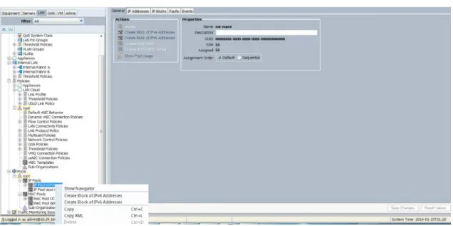
Adding Block of IP Addresses for KVM Access
The following steps provide the details for creating a block of KVM IP addresses for server access in the Cisco UCS environment.
1. Select the LAN tab at the top of the left window. 2. Select Pools > IpPools > Ip Pool ext-mgmt. 3. Right-click IP Pool ext-mgmt
16
Cisco UCS Common Platform Architecture Version 2 (CPAv2) for Big Data with Cloudera Fabric Configuration
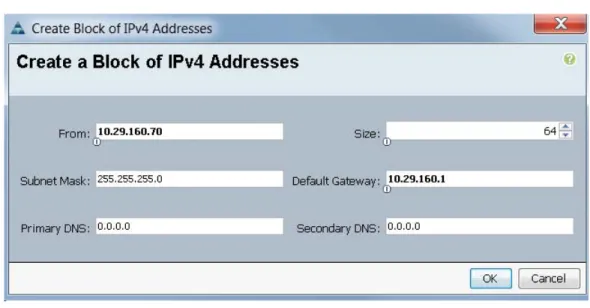
Figure 4 Adding a Block of IPv4 Addresses for KVM Access Part 1
5. Enter the starting IP address of the block and number of IPs needed, as well as the subnet and gateway information.
Figure 5 Adding a Block of IPv4 Addresses for KVM Access Part 2
6. Click OK to create the IP block. 7. ClickOKin the message box.
Fabric Configuration
Figure 6 Adding a Block of IPv4 Addresses for KVM Access Part 3
Editing Chassis and FEX Discovery Policy
The following steps provide the details for modifying the chassis discovery policy. Setting the discovery policy now will simplify the addition of future Cisco UCS B-Series Chassis and additional Fabric Extenders for other Cisco UCS C-Series connectivity.
1. Navigate to the Equipment tab in the left pane. 2. In the right pane, click the Policies tab.
3. Under Global Policies, change the Chassis/FEX Discovery Policy to 8-link. 4. Click Save Changes in the bottom right hand corner.
18
Cisco UCS Common Platform Architecture Version 2 (CPAv2) for Big Data with Cloudera Fabric Configuration
Figure 7 Chassis and FEX Discovery Policy
Enabling Server Ports and Uplink Ports
The following steps provide details for enabling server and uplinks ports: 1. Select the Equipment tab on the top left of the window.
2. Select Equipment > Fabric Interconnects > Fabric Interconnect A (primary) > Fixed Module.
3. Expand the Unconfigured Ethernet Ports section.
4. Select all the ports that are connected to the Cisco 2232 FEX (8 per FEX), right-click them, and select Reconfigure > Configure as a Server Port.
5. Select port 1 that is connected to the uplink switch, right-click, then select Reconfigure > Configure as Uplink Port.
6. Select Show Interface and select 10GB for Uplink Connection.
7. A pop-up window appears to confirm your selection. Click Yes then OK to continue. 8. SelectEquipment > Fabric Interconnects > Fabric Interconnect B
(subordinate) > Fixed Module
.
9. Expand the UnConfigured Ethernet Ports section.
10. Select all the ports that are connected to the Cisco 2232 Fabric Extenders (8 per Fex), right-click them, and select Reconfigure > Configure as Server Port.
11. A prompt displays asking if this is what you want to do. Click Yes then OK to continue. 12. Select port number 1, which is connected to the uplink switch, right-click, then select
Reconfigure > Configure as Uplink Port. 13. Select Show Interface and select 10GB for Uplink Connection.
Fabric Configuration
Figure 8 Enabling Server Ports
20
Cisco UCS Common Platform Architecture Version 2 (CPAv2) for Big Data with Cloudera Creating Pools for Service Profile Templates
Creating Pools for Service Profile Templates
Creating an Organization
Organizations are used as a means to arrange and restrict access to various groups within the IT organization, thereby enabling multi-tenancy of the compute resources. This document does not assume the use of Organizations; however the necessary steps are provided for future reference.
Follow these steps to configure an organization within the Cisco UCS Manager GUI: 1. Click New on the top left corner in the right pane in the Cisco UCS Manager GUI. 2. Select Create Organization from the options.
3. Enter a name for the organization.
4. (Optional) Enter a description for the organization. 5. Click OK.
6. Click OK in the success message box.
Creating MAC Address Pools
Follow these steps to create MAC address pools: 1. Select the LAN tab on the left of the window. 2. SelectPools > root
.
3. Right-click MAC Pools under the root organization.
4. Select Create MAC Poolto create the MAC address pool. Enter
ucs
for the name of the MAC pool.5. (Optional) Enter a description of the MAC pool. 6. Click Next.
7. Click Add.
8. Specify a starting MAC address.
9. Specify a size of the MAC address pool, which is sufficient to support the available server resources. 10. ClickOK.
Creating Pools for Service Profile Templates
Figure 10 Specifying the First MAC Address and Size
11. ClickFinish.
Figure 11 Adding MAC Addresses
12. When the message box displays, clickOK.
22
Cisco UCS Common Platform Architecture Version 2 (CPAv2) for Big Data with Cloudera Creating Pools for Service Profile Templates
Configuring VLANs
VLANs are configured as in shown in Table 5.
Table 5 VLAN Configurations
All of the VLANs created need to be trunked to the upstream distribution switch connecting the fabric interconnects. For this deployment vlan160_mgmt is configured for management access and user connectivity, vlan12_HDFS is configured for Hadoop interconnect traffic and vlan11_DATA is configured for optional secondary interconnect and/or SAN/NAS access, heavy ETL, etc. Follow these steps to configure VLANs in the Cisco UCS Manager GUI:
1. Select the LAN tab in the left pane in the Cisco UCS Manager GUI. 2. Select LAN > VLANs.
3. Right-click the VLANs under the root organization. 4. Select Create VLANs to create the VLAN.
Figure 13 Creating a VLAN
5. Enter vlan160_mgmt for the VLAN Name.
VLAN Fabric NIC Port Function Failover
vlan160_mgmt A eth0 Management, User
connectivity
Fabric Failover to B
vlan12_HDFS B eth1 Hadoop Fabric Failover to A
vlan11_DATA A eth2 Hadoop and/or
SAN/NAS access, ETL
Creating Pools for Service Profile Templates
6. Select Common/Global for vlan160_mgmt. 7. Enter 160 on VLAN IDs of the Create VLAN IDs. 8. Click OK and then, click Finish.
9. Click OK in the success message box.
Figure 14 Creating a Management VLAN
10. Select the LAN tab in the left pane again. 11. Select LAN > VLANs.
24
Cisco UCS Common Platform Architecture Version 2 (CPAv2) for Big Data with Cloudera Creating Pools for Service Profile Templates
18. Click OK in the success message box.
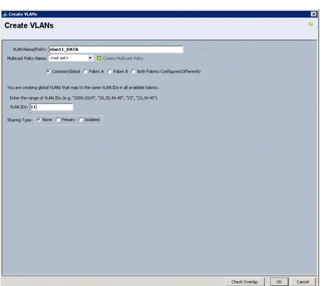
Figure 15 Creating VLAN Data
19. Select the LAN tab in the left pane. 20. Select LAN > VLANs.
21. Right-click the VLANs under the root organization. 22. Select Create VLANs to create the VLAN.
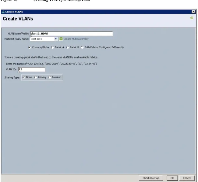
23. Enter vlan12_HDFS for the VLAN Name. 24. Select Common/Global for the vlan12_HDFS. 25. Enter 12 on VLAN IDs of the Create VLAN IDs. 26. Click OK and then, click Finish.
Creating Pools for Service Profile Templates
Figure 16 Creating VLAN for Hadoop Data
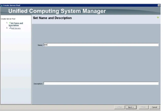
Creating Server Pool
A server pool contains a set of servers. These servers typically share the same characteristics. Those characteristics can be their location in the chassis, or an attribute such as server type, amount of memory, local storage, type of CPU, or local drive configuration. You can manually assign a server to a server pool, or use server pool policies and server pool policy qualifications to automate the assignment Follow these steps to configure the server pool within the Cisco UCS Manager GUI:
26
Cisco UCS Common Platform Architecture Version 2 (CPAv2) for Big Data with Cloudera Creating Pools for Service Profile Templates
7. Click Next to add the servers.
Figure 17 Setting the Name and Description of the Server Pool
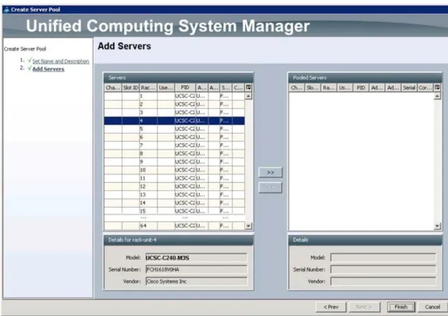
8. Select all the Cisco UCS C240M3S servers to be added to the server pool you previously created (ucs), then Click >> to add them to the pool.
9. Click Finish.
Creating Policies for Service Profile Templates
Figure 18 Adding Servers to the Server Pool
Creating Policies for Service Profile Templates
Creating Host Firmware Package Policy
Firmware management policies allow the administrator to select the corresponding packages for a given server configuration. These include adapters, BIOS, board controllers, FC adapters, HBA options, ROM and storage controller properties as applicable.
Follow these steps to create a firmware management policy for a given server configuration using the Cisco UCS Manager GUI:
1. Select the Servers tab in the left pane in the Cisco UCS Manager GUI. 2. SelectPolicies > root.
28
Cisco UCS Common Platform Architecture Version 2 (CPAv2) for Big Data with Cloudera Creating Policies for Service Profile Templates
9. Click OK.
Figure 19 Creating a Host Firmware Package
Creating QoS Policies
Follow these steps to create the QoS policy for a given server configuration using the Cisco UCS Manager GUI:
Best Effort Policy
1. Select the LANtab in the left pane in the UCS Manager GUI. 2. SelectPolicies > root.
3. Right-click QoS Policies. 4. SelectCreate QoS Policy.
Creating Policies for Service Profile Templates
Figure 20 Creating a QoS Policy
1. Enter BestEffort as the name of the policy. 2. Select BestEffort from the drop down menu. 3. Keep the Burst(Bytes) field as default (10240). 4. Keep the Rate(Kbps) field as default (line-rate). 5. Keep Host Control radio button as default (none).
30
Cisco UCS Common Platform Architecture Version 2 (CPAv2) for Big Data with Cloudera Creating Policies for Service Profile Templates
Figure 21 Creating a BestEffort Policy
Platinum Policy
1. Select the LAN tab in the left pane in the Cisco UCS Manager GUI. 2. Select Policies > root.
3. Right-click QoS Policies. 4. Select Create QoS Policy.
5. Enter Platinum as the name of the policy. 6. Select Platinum from the drop down menu. 7. Keep the Burst(Bytes) field as default (10240). 8. Keep the Rate(Kbps) field as default (line-rate). 9. Keep Host Control radio button as default (none).
Creating Policies for Service Profile Templates
Figure 22 Creating a Platinum QoS Policy
Setting Jumbo Frames
Follow these steps for setting Jumbo frames and enabling QoS:
1. Select the LAN tab in the left pane in the Cisco UCS Manager GUI. 2. Select LAN Cloud > QoS System Class.
3. In the right pane, select the General tab 4. In the Platinum row, enter 9000 for MTU. 5. Check the Enabled Check box next to Platinum. 6. In the Best Effort row, select best-effort for weight. 7. In the Fiber Channel row, select none for weight. 8. Click Save Changes.
32
Cisco UCS Common Platform Architecture Version 2 (CPAv2) for Big Data with Cloudera Creating Policies for Service Profile Templates
Figure 23 Setting Jumbo Frames
Creating Local Disk Configuration Policy
Follow these steps to create local disk configuration in the Cisco UCS Manager GUI: 1. Select the Servers tab on the left pane in the UCS Manager GUI.
2. Go to Policies > root.
3. Right-click Local Disk Config Policies.
4. Select Create Local Disk Configuration Policy.
5. Enter ucs as the local disk configuration policy name.
6. Change the Mode to Any Configuration. Uncheck the Protect Configuration box. 7. Keep the FlexFlash State field as default (Disable).
8. Keep the FlexFlash RAID Reporting State field as default (Disable). 9. Click OK to complete the creation of the Local Disk Configuration Policy. 10. ClickOK.
Creating Policies for Service Profile Templates
Figure 24 Configuring a Local Disk Policy
Creating Server BIOS Policy
The BIOS policy feature in Cisco Unified Computing System automates the BIOS configuration process. The traditional method of setting the BIOS is done manually and is often error-prone. By creating a BIOS policy and assigning the policy to a server or group of servers, you can enable transparency within the BIOS settings configuration.
34
Cisco UCS Common Platform Architecture Version 2 (CPAv2) for Big Data with Cloudera Creating Policies for Service Profile Templates
2. SelectPolicies > root. 3. Right-click BIOS Policies. 4. SelectCreate BIOS Policy.
5. Enter your preferred BIOS policy name (ucs).
6. Change the BIOS settings as shown in the following figures:
Creating Policies for Service Profile Templates
36
Cisco UCS Common Platform Architecture Version 2 (CPAv2) for Big Data with Cloudera Creating Policies for Service Profile Templates
Figure 27 Creating a Server BIOS Policy for Intel Directed IO
7. ClickFinishto complete creating the BIOS policy. 8. ClickOK.
Creating Policies for Service Profile Templates
Figure 28 Creating a Server BIOS Policy for Memore
Creating Boot Policy
Follow these steps to create boot policies within the Cisco UCS Manager GUI: 1. Select theServerstab in the left pane in the Cisco UCS Manager GUI. 2. SelectPolicies > root.
3. Right-click theBoot Policies. 4. SelectCreate Boot Policy.
38
Cisco UCS Common Platform Architecture Version 2 (CPAv2) for Big Data with Cloudera Creating Policies for Service Profile Templates
Figure 29 Creating a Boot Policy Part 1
5. Enterucsas the boot policy name.
6. (Optional) enter a description for the boot policy.
7. Keep the Reboot on Boot Order Change check box unchecked. 8. Keep Enforce vNIC/vHBA/iSCSI Name check box checked. 9. Keep Boot Mode Default (Legacy).
10. Expand Local Devices > Add CD/DVD and select Add Local CD/DVD. 11. Expand Local Devices > Add Local Disk and select Add Local LUN. 12. Expand vNICs and select Add LAN Boot and enter eth0.
13. Click OK to add the Boot Policy. 14. Click OK.
Creating Service Profile Template
Figure 30 Creating Boot Policy Part 2
Creating Service Profile Template
Follow these steps to create a service profile template:1. Select the Servers tab in the left pane in the Cisco UCS Manager GUI. 2. Right-click Service Profile Templates.
40
Cisco UCS Common Platform Architecture Version 2 (CPAv2) for Big Data with Cloudera Creating Service Profile Template
Figure 31 Creating a Service Profile Template
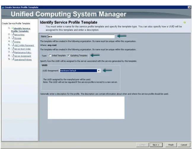
The Create Service Profile Template window appears.
The following steps provide a detailed configuration procedure to identify the service profile template: a. Name the service profile template ucs. Select theUpdating Templateradio button. b. In the UUID section, selectHardware Defaultas the UUID pool.
Creating Service Profile Template
Figure 32 Identify a Service Profile Template
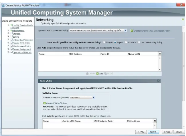
Configuring Network Settings for the Template
1. Keep the Dynamic vNIC Connection Policy field at the default.
2. Select Expert radio button for the option how would you like to configure LAN connectivity? 3. Click Add to add a vNIC to the template.
42
Cisco UCS Common Platform Architecture Version 2 (CPAv2) for Big Data with Cloudera Creating Service Profile Template
Figure 33 Configuring Network Settings for the Template
4. The Create vNIC window displays. Name the vNIC as eth0. 5. Select ucs in the Mac Address Assignment pool.
6. Select the Fabric A radio button and check the Enable failover check box for the Fabric ID. 7. Check the vlan160_mgmt check box for VLANs and select the Native VLAN radio button. 8. Select MTU size as 1500
9. Select adapter policy as Linux 10. Select QoS Policy as BestEffort.
11. Keep the Network Control Policy as Default. 12. Keep the Connection Policies as Dynamic vNIC.
13. Keep the Dynamic vNIC Connection Policy as <not set>. 14. Click OK.
Creating Service Profile Template
Figure 34 Configuring vNIC eth0
44
Cisco UCS Common Platform Architecture Version 2 (CPAv2) for Big Data with Cloudera Creating Service Profile Template
23. Keep the Connection Policies as Dynamic vNIC.
24. Keep the Dynamic vNIC Connection Policy as <not set>. 25. Click OK.
Figure 35 Configuring vNIC eth1
26. The Create vNIC window appears. Name the vNIC eth2. 27. Select ucs in the Mac Address Assignment pool.
Creating Service Profile Template
29. Check the vlan11_DATA check box for VLANs and select the Native VLAN radio button 30. Select MTU size as 9000
31. Select adapter policy as Linux 32. Select QoS Policy as Platinum.
33. Keep the Network Control Policy as Default. 34. Keep the Connection Policies as Dynamic vNIC.
35. Keep the Dynamic vNIC Connection Policy as <not set>. 36. Click OK.
46
Cisco UCS Common Platform Architecture Version 2 (CPAv2) for Big Data with Cloudera Creating Service Profile Template
Figure 36 Configuring vNIC eth2
Configuring Storage Policy for the Template
Follow these steps to configure storage policies: 1. Select ucs for the local disk configuration policy.
2. Select the No vHBAs radio button for the option for How would you like to configure SAN connectivity?
Creating Service Profile Template
Figure 37 Configuring Storage Settings
48
Cisco UCS Common Platform Architecture Version 2 (CPAv2) for Big Data with Cloudera Creating Service Profile Template
Figure 38 Configure Zoning
Configuring vNIC/vHBA Placement for the Template
Follow these steps to configure vNIC/vHBA placement policy:
1. Select the Default Placement Policy option for the Select Placement field. 2. Select eth0, eth1 and eth2 assign the vNICs in the following order:
a. eth0 b. eth1 c. eth2
3. Review to make sure that all of the vNICs were assigned in the appropriate order. 4. Click Next to continue to the next section.
Creating Service Profile Template
Figure 39 vNIC/vHBA Placement
Configuring Server Boot Order for the Template
Follow these steps to set the boot order for servers: 1. Select ucs in the Boot Policy name field.
2. Check the Enforce vNIC/vHBA/iSCSI Name check box.
3. Review to make sure that all of the boot devices were created and identified. 4. Verify that the boot devices are in the correct boot sequence.
5. Click OK. 6. Click Next.
50
Cisco UCS Common Platform Architecture Version 2 (CPAv2) for Big Data with Cloudera Creating Service Profile Template
Figure 40 Creating a Boot Policy
7. In the Maintenance Policy window, follow these steps to apply the maintenance policy: a. Keep the Maintenance policy at no policy used by default.
b. ClickNextto continue to the next section.
Configuring a Server Assignment for the Template
In the Server Assignment window, follow these steps to assign the servers to the pool: 1. Select ucs for the Pool Assignment field.
2. Keep the Server Pool Qualification field at default. 3. Selectucs in Host Firmware Package.
Creating Service Profile Template
Figure 41 Server Assignment
Configuring Operational Policies for the Template
In the Operational Policies Window, follow these steps: 1. Select ucs in the BIOS Policy field.
2. Click Finish to create the Service Profile template. 3. ClickOKin the pop-up window to proceed.
52
Cisco UCS Common Platform Architecture Version 2 (CPAv2) for Big Data with Cloudera Creating Service Profile Template
Figure 42 Selecting a BIOS Policy
4. Select the Servers tab in the left pane of the Cisco UCS Manager GUI. a. Go to Service Profile Templates > root.
b. Right-click Service Profile Templates ucs. c. SelectCreate Service Profiles From Template.
Creating Service Profile Template
Figure 43 Creating Service Profiles from a Template
The Create Service Profile from Template window appears.
54
Cisco UCS Common Platform Architecture Version 2 (CPAv2) for Big Data with Cloudera Configuring Disk Drives for OS on Name Nodes
Figure 45 Cisco UCS Manager Displaying All Nodes
Configuring Disk Drives for OS on Name Nodes
Namenode and Secondary Namenode have a different RAID configuration compared to Data nodes. This section details the configuration of disk drives for OS on these nodes (rhel1 and rhel2). The disk drives are configured as RAID1, read ahead cache is enabled and write cache is enabled while battery is present. The first two disk drives are used for operating system and remaining 22 disk drives are using for HDFS as described in the following sections.
There are several ways to configure RAID; using LSI WebBIOS Configuration Utility embedded in the MegaRAID BIOS, booting DOS and running MegaCLI commands, using Linux based MegaCLI commands, or using third party tools that have MegaCLI integrated. For this deployment, the first two disk drives are configured using LSI WebBIOS Configuration Utility and rests are configured using Linux based MegaCLI commands after the completion of the Operating system Installation.
Follow these steps to create RAID1 on the first two disk drives to install the operating system: 1. When the server is booting, the following text appears on the screen:
a. Press <Ctrl><H> to launch the WebBIOS. b. Press Ctrl+H immediately.
The Adapter Selection window appears. 2. Click Start to continue.
Configuring Disk Drives for OS on Name Nodes
Figure 46 Adapter Selection for FAID Configuraiton
4. In the configuration wizard window, choose Clear Configuration and click Next to clear the existing configuration.
56
Cisco UCS Common Platform Architecture Version 2 (CPAv2) for Big Data with Cloudera Configuring Disk Drives for OS on Name Nodes
Figure 48 Confirming Clearance of the Previous Configuration on the Controller
8. In the Configuration Wizard window, choose the configuration type to be New Configuration and click Next.
Configuring Disk Drives for OS on Name Nodes
Figure 49 Creating a New Configuration
9. Select the configuration method to be Manual Configuration; this enables you to have complete control over all attributes of the new storage configuration, such as, the drive groups, virtual drives and the ability to set their parameters.
58
Cisco UCS Common Platform Architecture Version 2 (CPAv2) for Big Data with Cloudera Configuring Disk Drives for OS on Name Nodes
Figure 50 Manual Configuration Method
11. The Drive Group Definition window appears. Use this window to choose the first two drives to create drive group.
12. Click Add to Array to move the drives to a proposed drive group configuration in the Drive Groups pane. Click Accept DG and then, click Next.
Configuring Disk Drives for OS on Name Nodes
Figure 51 Selecting First Drive and Adding to Drive Group
60
Cisco UCS Common Platform Architecture Version 2 (CPAv2) for Big Data with Cloudera Configuring Disk Drives for OS on Name Nodes
Figure 52 Span Definition Window
14. In the Virtual Drive definitions window, a. Click Update Size.
b. Change Strip Size to 64 KB. A larger strip size produces higher read performance c. From the Read Policy drop-down list, choose Always Read Ahead.
d. From the Write Policy drop-down list, choose Write Back with BBU. e. Make sure RAID Level is set to RAID1.
f. Click Accept to accept the changes to the virtual drive definitions. g. Click Next.
Note Clicking Update Size might change some of the settings in the window. Make sure all settings are correct before accepting.
Configuring Disk Drives for OS on Name Nodes
Figure 53 Virtual Drive Definition Window
15. After you finish the virtual drive definitions, click Next. The Configuration Preview window appears showing VD0.
16. Check the virtual drive configuration in the Configuration Preview window and click Accept to save the configuration.
62
Cisco UCS Common Platform Architecture Version 2 (CPAv2) for Big Data with Cloudera Configuring Disk Drives for OS on Name Nodes
Figure 54 Completed Virtual Drive Definition
17. Click Yes to save the configuration.
Configuring Disk Drives for OS on Name Nodes
Figure 55 SSD Caching Window
64
Cisco UCS Common Platform Architecture Version 2 (CPAv2) for Big Data with Cloudera Configuring Disk Drives for OS on Name Nodes
Figure 56 Initializing Virtual Drive Window
20. Set VD0 as the Boot Drive and click Go. 21. Click Home.
Configuring Disk Drives for OS on Data Nodes
Figure 57 Setting Virtual Drive as Boot Drive
Configuring disks 3-24 are done using Linux based MegaCLI command as described in the section about Configuring Data Drives for Namenode later in this document.
Configuring Disk Drives for OS on Data Nodes
Nodes 3 through 64 are configured as data nodes. This section details the configuration of disk drives for OS on the data nodes. As stated above, the focus of this CVD is the High Performance Configuration featuring 24 1TB SFF disk drives. The disk drives are configured as individual RAID0 volumes with 1MB stripe size. Read ahead cache and write cache is enabled while battery is present. The first disk drive is used for operating system and remaining 23 disk drives are using for HDFS as described in the following sections.
66
Cisco UCS Common Platform Architecture Version 2 (CPAv2) for Big Data with Cloudera Configuring Disk Drives for OS on Data Nodes
There are several ways to configure RAID: using LSI WebBIOS Configuration Utility embedded in the MegaRAID BIOS, booting DOS and running MegaCLI commands, using Linux based MegaCLI commands, or using third party tools that have MegaCLI integrated. For this deployment, the first disk drive is configured using LSI WebBIOS Configuration Utility and rest is configured using Linux based MegaCLI commands after the OS is installed.
Follow these steps to create RAID0 on the first disk drive to install the operating system: 1. When the server is booting, the following text appears on the screen:
a. Press <Ctrl><H> to launch the WebBIOS. b. Press Ctrl+H immediately.
The Adapter Selection window appears. 2. Click Start to continue.
3. Click Configuration Wizard.
Figure 58 Adapter Selection for RAID Configuration
4. In the configuration wizard window, choose Clear Configuration and click Next to clear the existing configuration.
Configuring Disk Drives for OS on Data Nodes
Figure 59 Clearing the Current Configuration
5. Choose Yes when asked to confirm the wiping of the current configuration. 6. In the Physical View, ensure that all the drives are Unconfigured Good. 7. Click Configuration Wizard.
68
Cisco UCS Common Platform Architecture Version 2 (CPAv2) for Big Data with Cloudera Configuring Disk Drives for OS on Data Nodes
Figure 60 Confirming the Clearance of the Previous Configuration on the Controller
8. In the Configuration Wizard window choose the configuration type to be New Configuration and click Next.
Configuring Disk Drives for OS on Data Nodes
Figure 61 Creating a New Configuration
9. Select the configuration method to be Manual Configuration; this enables you to have complete control over all attributes of the new storage configuration, such as, the drive groups, virtual drives and the ability to set their parameters.
70
Cisco UCS Common Platform Architecture Version 2 (CPAv2) for Big Data with Cloudera Configuring Disk Drives for OS on Data Nodes
Figure 62 Manual Configuration Method
The Drive Group Definition window appears. Use this window to choose the first drive to create drive groups.
11. Click Add to Array to move the drives to a proposed drive group configuration in the Drive Groups pane.
Configuring Disk Drives for OS on Data Nodes
Figure 63 Selecting First Drive and Adding to Drive Group
72
Cisco UCS Common Platform Architecture Version 2 (CPAv2) for Big Data with Cloudera Configuring Disk Drives for OS on Data Nodes
Figure 64 Span Definition Window
14. In the Virtual Drive definitions window: a. Click Update Size.
b. Change Strip Size to 1MB. A larger strip size produces higher read performance c. From the Read Policy drop-down list, choose Always Read Ahead.
d. From the Write Policy drop-down list, choose Write Back with BBU. e. Make sure RAID Level is set to RAID0.
f. Click Accept to accept the changes to the virtual drive definitions. g. Click Next.
Note Clicking Update Size might change some of the settings in the window. Make sure all settings are correct before accepting.
Configuring Disk Drives for OS on Data Nodes
Figure 65 Virtual Drive Definition Window
15. After finishing the virtual drive definitions, click Next. The Configuration Preview window appears showing VD0.
16. Check the virtual drive configuration in the Configuration Preview window and click Accept to save the configuration.
74
Cisco UCS Common Platform Architecture Version 2 (CPAv2) for Big Data with Cloudera Configuring Disk Drives for OS on Data Nodes
Figure 66 Completed Virtual Drive Definition
17. Click Yes to save the configuration.
Configuring Disk Drives for OS on Data Nodes
Figure 67 SSD Caching Window
76
Cisco UCS Common Platform Architecture Version 2 (CPAv2) for Big Data with Cloudera Configuring Disk Drives for OS on Data Nodes
Figure 68 Initializing the Virtual Drive Window
Installing Red Hat Linux 6.4 with KVM
Figure 69 Setting Virtual Drive as Boot Drive
21. Click Home.
22. Review the Configuration and click Exit.
The steps above can be repeated to configure disks 2-24 or using Linux based MegaCLI commands as described in Section on Configuring Data Drives later in this document.
Installing Red Hat Linux 6.4 with KVM
The following section provides detailed procedures for installing Red Hat Linux 6.4.
There are multiple methods to install Red Hat Linux operating system. The installation procedure described in this deployment guide uses KVM console and virtual media from Cisco UCS Manager.
78
Cisco UCS Common Platform Architecture Version 2 (CPAv2) for Big Data with Cloudera Installing Red Hat Linux 6.4 with KVM
Figure 70 Selecting KVM Console Option
5. In the KVM window, select the Virtual Media tab.
6. Click the Add Image button found in the right hand corner of the Virtual Media selection window. 7. Browse to the Red Hat Enterprise Linux Server 6.4 installer ISO image file.
Installing Red Hat Linux 6.4 with KVM
Figure 71 Adding an ISO Image
80
Cisco UCS Common Platform Architecture Version 2 (CPAv2) for Big Data with Cloudera Installing Red Hat Linux 6.4 with KVM
Figure 72 Browse to the Red Hat Enterprise Linux ISO Image
9. Check the check box for Mapped, next to the entry corresponding to the image you just added. 10. In the KVM window, select the KVM tab to monitor during boot.
11. In the KVM window, select the Boot Server button in the upper left corner. 12. Click OK.
Installing Red Hat Linux 6.4 with KVM
Figure 73 Mapping ISO Image
14. On reboot, the machine detects the presence of the Red Hat Enterprise Linux Server 6.4 install media.
82
Cisco UCS Common Platform Architecture Version 2 (CPAv2) for Big Data with Cloudera Installing Red Hat Linux 6.4 with KVM
Figure 74 Select the Install Option
Installing Red Hat Linux 6.4 with KVM
Figure 75 Skip the Media Test
84
Cisco UCS Common Platform Architecture Version 2 (CPAv2) for Big Data with Cloudera Installing Red Hat Linux 6.4 with KVM
Figure 76 Red Hat Linux Welcome Screen
Installing Red Hat Linux 6.4 with KVM
Figure 77 Select the Language for the Installation
86
Cisco UCS Common Platform Architecture Version 2 (CPAv2) for Big Data with Cloudera Installing Red Hat Linux 6.4 with KVM
Figure 78 Select the Basic Storage Device
20. Select Fresh Installation.
Installing Red Hat Linux 6.4 with KVM
Figure 79 Select Fresh Installation
22. Click Configure Network. The Network Connections window should then appear. 23. In the Network Connections window, select the wired tab.
24. Select the interface System eth0 and click Edit. 25. Editing System eth0 appears.
26. Check the check box Connect automatically. 27. In the drop down menu select Manual Method.
28. Click Add and enter IP Address, Netmask and the Gateway. 29. For this demonstration we use the following:
IP Address: 10.29.160.53 Netmask: 255.255.255.0 Gateway: 10.29.160.1
88
Cisco UCS Common Platform Architecture Version 2 (CPAv2) for Big Data with Cloudera Installing Red Hat Linux 6.4 with KVM
Figure 80 Configure the Network for eth0
32. Repeat the steps 26 to steps 32 for system eth1 with the following:
IP Address: 192.168.12.11 Netmask: 255.255.255.0
Installing Red Hat Linux 6.4 with KVM
Figure 81 Configure the Network for eth1
33. Repeat the steps 26 to steps 32 for system eth2 with the following:
IP Address: 192.168.11.11 Netmask: 255.255.255.0
Note Table 6 lists the IP address of nodes in the cluster.
90
Cisco UCS Common Platform Architecture Version 2 (CPAv2) for Big Data with Cloudera Installing Red Hat Linux 6.4 with KVM
Figure 82 Select the Time Zone
Installing Red Hat Linux 6.4 with KVM
Figure 83 Enter the Root Password
36. Select Use All Space and click Next. 37. Choose an appropriate boot drive.
92
Cisco UCS Common Platform Architecture Version 2 (CPAv2) for Big Data with Cloudera Installing Red Hat Linux 6.4 with KVM
Figure 84 Select the Installation Options
38. Click Write changes to the disk and click Next.
Figure 85 Confirm the Disk Format
Installing Red Hat Linux 6.4 with KVM
Figure 86 Select the Type of Installation
94
Cisco UCS Common Platform Architecture Version 2 (CPAv2) for Big Data with Cloudera Installing Red Hat Linux 6.4 with KVM
Installing Red Hat Linux 6.4 with KVM
Figure 88 Installation in Progress
41. When the installation is complete reboot the system.
42. Repeat steps (step1 to 41) to install Red Hat Linux on Servers 2 through 64.
Note You can automate the OS installation and configuration of the nodes through the Preboot Execution Environment (PXE) boot or through third party tools.
The hostnames and their corresponding IP addresses are shown in Table 6.
Table 6 Hostnames and IP Addresses
96
Cisco UCS Common Platform Architecture Version 2 (CPAv2) for Big Data with Cloudera Post OS Installation Configuration
Post OS Installation Configuration
Choose one of the nodes of the cluster or a separate node as Admin Node for management such as CDH installation, parallel shell, creating a local Red Hat repository and others. In this document, we use rhel1 for this suppose.
Setting Up Password-less Login
To manage all of the clusters nodes from the admin node we need to setup password-less login. It assists in automating common tasks with Parallel-SSH (pssh) and shell-scripts without having to use passwords. When Red Hat Linux is installed across all the nodes in the cluster, follow the steps below in order to enable password less login across all the nodes.
1. Login to the Admin Node (rhel1)
ssh 10.29.160.53
2. Run the ssh-keygen command to create both public and private keys on the admin node.
rhel8 10.29.160.60 192.168.12.18 192.168.11.18 rhel9 10.29.160.61 192.168.12.19 192.168.11.19 rhel10 10.29.160.62 192.168.12.20 192.168.11.20 rhel11 10.29.160.63 192.168.12.21 192.168.11.21 rhel12 10.29.160.64 192.168.12.22 192.168.11.22 rhel13 10.29.160.65 192.168.12.23 192.168.11.23 rhel14 10.29.160.66 192.168.12.24 192.168.11.24 rhel15 10.29.160.67 192.168.12.25 192.168.11.25 rhel16 10.29.160.68 192.168.12.26 192.168.11.26 … … … … rhel64 10.29.160.116 192.168.12.74 192.168.11.74
Post OS Installation Configuration
3. Run the following command from the admin node to copy the public key id_rsa.pub to all the nodes of the cluster. ssh-copy-id appends the keys to the remote-host's .ssh/authorized_key.
for IP in {53..116}; do echo -n "$IP -> "; ssh-copy-id -i ~/.ssh/id_rsa.pub 10.29.160.$IP; done
4. Enter yes for Are you sure you want to continue connecting (yes/no)?
5. Enter the password of the remote host.
Setting Up Password-less Login
To manage all of the clusters nodes from the admin node we need to setup password-less login. It assists in automating common tasks with Parallel-SSH (pssh) and shell-scripts without having to use passwords. When Red Hat Linux is installed across all the nodes in the cluster, follow the steps below in order to enable password less login across all the nodes.
1. Log into the Admin Node (rhel1)
98
Cisco UCS Common Platform Architecture Version 2 (CPAv2) for Big Data with Cloudera Post OS Installation Configuration
1. Run the following command from the admin node to copy the public key id_rsa.pub to all the nodes of the cluster. ssh-copy-id appends the keys to the remote-host's .ssh/authorized_key.
for IP in {53..116}; do echo -n "$IP -> "; ssh-copy-id -i ~/.ssh/id_rsa.pub 10.29.160.$IP; done
2. Enter yes for Are you sure you want to continue connecting (yes/no)?
3. Enter the password of the remote host.
Installing and Configuring Parallel Shell
PARALLEL-SSH
Parallel SSH is used to run commands on several hosts at the same time. It takes a file of hostnames and a bunch of common ssh parameters as parameters, executes the given command in parallel on the nodes specified.
1. From the system that is connected to the Internet, download pssh.
Post OS Installation Configuration
scp pssh-2.3.1.tar.gz rhel1:/root
2. Copy pssh-2.3.1.tar.gz to the Admin Node
ssh rhel1
tar xzf pssh-2.3.1.tar.gz cd pssh-2.3.1
100
Cisco UCS Common Platform Architecture Version 2 (CPAv2) for Big Data with Cloudera Post OS Installation Configuration
vi /root/allnodes
# This file contains ip address of all nodes of the cluster #used by parallel-shell (pssh). For Details man pssh 10.29.160.53 10.29.160.54 10.29.160.55 10.29.160.56 10.29.160.57 10.29.160.58 10.29.160.59 10.29.160.60 10.29.160.61 10.29.160.62 10.29.160.63 10.29.160.64 10.29.160.65 10.29.160.66 10.29.160.67 10.29.160.68 ... 10.29.160.116 vi /root/datanodes 10.29.160.55 10.29.160.56 10.29.160.57 10.29.160.58 10.29.160.59 10.29.160.60 10.29.160.61 10.29.160.62 10.29.160.63 10.29.160.64 10.29.160.65 10.29.160.66 10.29.160.67
Post OS Installation Configuration
10.29.160.68 ...
10.29.160.116
Cluster Shell
1. From the system connected to the Internet download Cluster shell (clush) and install it on rhel1. Cluster shell is available from EPEL (Extra Packages for Enterprise Linux) repository.
wget
http://dl.fedoraproject.org/pub/epel//6/x86_64/clustershell-1.6-1.el6.noarch .rpm
scp clustershell-1.6-1.el6.noarch.rpm rhel1:/root/
2. Login to rhel1 and install cluster shell
yum install clustershell-1.6-1.el6.noarch.rpm
3. Edit /etc/clustershell/groups file to include hostnames for all the nodes of the cluster. 4. For 64 node cluster all: rhel[1-64]
Configuring /etc/hosts
Follow the steps below to create the host file across all the nodes in the cluster:
1. Populate the host file with IP addresses and corresponding hostnames on the Admin node (rhel1).
vi /etc/hosts
127.0.0.1 localhost localhost.localdomain localhost4 localhost4.localdomain4 ::1 localhost localhost.localdomain localhost6 localhost6.localdomain6 192.168.12.11 rhel1 192.168.12.12 rhel2 192.168.12.13 rhel3 192.168.12.14 rhel4 192.168.12.15 rhel5 192.168.12.16 rhel6 192.168.12.17 rhel7 192.168.12.18 rhel8 192.168.12.19 rhel9 192.168.12.20 rhel10 192.168.12.21 rhel11 192.168.12.22 rhel12 192.168.12.23 rhel13 192.168.12.24 rhel14
102
Cisco UCS Common Platform Architecture Version 2 (CPAv2) for Big Data with Cloudera Post OS Installation Configuration
Creating Red Hat Local Repository
To create a repository using RHEL DVD or ISO on the admin node (in this deployment rhel1 is used for this purpose), create a directory with all the required RPMs, run the createrepo command and then publish the resulting repository.
1. Log into rhel1. Create a directory that would contain the repository.
mkdir -p /var/www/html/rhelrepo
2. Copy the contents of the Red Hat DVD to /var/www/html/rhelrepo
3. Alternatively, if you have access to a Red Hat ISO Image, Copy the ISO file to rhel1.
scp rhel-server-6.4-x86_64-dvd.iso rhel1:/root
Here we assume you have the Red Hat ISO file located in your present working directory.
mkdir -p /mnt/rheliso
mount -t iso9660 -o loop /root/rhel-server-6.4-x86_64-dvd.iso /mnt/rheliso/
4. Copy the contents of the ISO to the /var/www/html/rhelrepo directory
cp -r /mnt/rheliso/* /var/www/html/rhelrepo
5. On rhel1 create a.repo file to enable the use of the yum command.