A PARALLEL PLATE REACTOR BUILT WITH WALL MATERIALS FOR INDOOR SURFACE CHEMISTRY STUDY
Liyong Cui
A thesis submitted to the faculty of the University of North Carolina at Chapel Hill in partial fulfillment of the requirements for the degree of Master of Science in the Department of Environmental Science and Engineering in the Gillings School of Global Public Health.
Chapel Hill 2019
© 2019 Liyong Cui
ABSTRACT
Liyong Cui: A Parallel Plate Reactor Built with Wall Materials for Indoor Surface Chemistry Study
(Under the direction of Barbara J. Turpin)
Indoor air exposures in damp homes are associated with adverse health effects. These associations might be explained, in part, by indoor surface chemistry. In this study, a parallel plate laminar flow reactor was designed to understand the hygroscopicity of indoor surfaces and indoor gas reactive uptake. We introduced three parallel plate flow reactor scenarios:
continuously mixed flow reactor (CMFR), plug flow reactor, and laminar flow reactor to
TABLE OF CONTENTS
LIST OF TABLES ... vi
LIST OF FIGURES ... vii
CHAPTER 1: INTRODUCTION ... 1
CHAPTER 2: DESIGN ... 4
CHAPTER 3: MODELS ... 7
3.1 Continuously mixed flow reactor (CMFR) model ... 7
3.1.1 Basic concepts ... 7
3.1.2 CMFR model development ... 9
3.1.3 Discussion ... 13
3.2 Parallel plate plug flow reactor model ... 14
3.2.1 Review of cylindrical plug flow reactors ... 14
3.2.2 Parallel plate plug flow reactor model development ... 16
3.2.3 Discussion ... 18
3.3.1 Test for a well-developed laminar flow ... 20
3.3.2 Existing model for parallel plate laminar flow reactor ... 21
CHAPTER 4: APPLICATIONS ... 22
4.1. Hygroscopicity of indoor surfaces ... 22
4.2. Reactive uptake of gases to indoor surfaces ... 24
CHAPTER 5: CONCLUSION ... 26
LIST OF TABLES
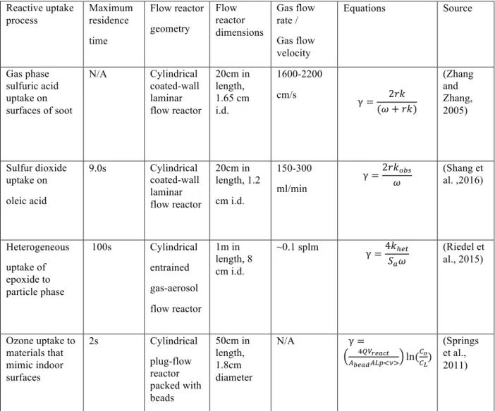
TABLE 1:SUMMARIES OF SEVERAL RECENT FLOW TUBE EXPERIMENTS ... 4
LIST OF FIGURES
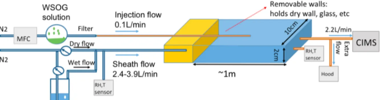
FIGURE 1:PARALLEL PLATE FLOW REACTOR DESIGNED FOR APPLICATIONS ... 6
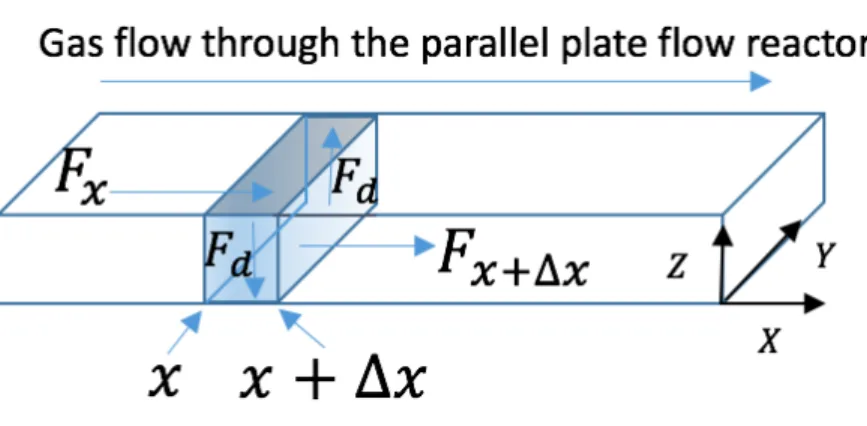
FIGURE 2:MASS BALANCE MODEL ... 16
FIGURE 3:PLOT OF OZONE UPTAKE WITH DIFFERENT Γ WHEN Ν1=0.02 CM/S,Q=4.0L/MIN ... 19
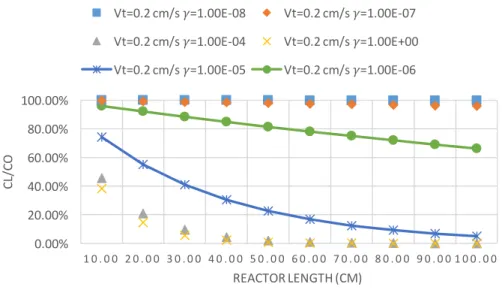
FIGURE 4:PLOT OF OZONE UPTAKE WITH DIFFERENT ΓWHEN Ν1=0.2 CM/S,Q=2.5L/MIN ... 20
CHAPTER 1: INTRODUCTION
Indoor air exposures in damp homes are associated with adverse health effects like asthma and allergy, respiratory infections, lower or upper respiratory symptoms and specific neurologic symptoms, etc. (Mendell & Health, 2005). These adverse effects associated with “dampness” are explained in part by microbial exposures (Fisk et al., 2007; Mendell et al., 2011). They could also be linked to chemical exposures indoors, since indoor air reactions can function as a major source or sink for many highly reactive compounds (Weschler, 2004; Dancen et al., 2018). Indoor particle generation (Weschler & Shields, 1999; Destaillats et al., 2006), primary emission from indoor materials, secondary emissions of organic compounds from gas phase ozone derived reactions (Morrison & Nazaroff, 2002) or from heterogeneous reactions occurring on indoor surfaces (Weschler, 2004), and outdoor-to-indoor transport, all significantly contribute to indoor air-pollutant exposures.
Coleman et al., 2008; Pandrangi & Morrison, 2008). Third, heterogeneous processes on surfaces help to explain observed discrepancies between experimental measurements and calculations that are based solely on gas phase chemistry. For example, light-induced heterogeneous reactions are reported to lead to substantial indoor •OH radical formation and therefore substantially influence the oxidizing capability of indoor air (Gómez Alvarez et al., 2012).
However, indoor surface processes are much harder to investigate than gas-phase reactions because of their complexity. A major limitation in evaluating the surface chemistry is the inability to measure the heterogeneous uptake rate of compounds of interest in an indoor setting. Indoor surface uptake and subsequent heterogeneous reactions are thought to play an important role in the loss of indoor oxygenated volatile organic compounds (OVOCs) especially in damp homes (Duncan et al.,2018). Duncan et al. (2018) found that concentrations of total water-soluble organic gas (WSOGs) are substantially higher indoors than outdoors (N = 13 homes) and characterized numerous reactive gases that are potential precursors to such reactions. Also, measurements of liquid water (or surface sorbed water) are also limited, inhibiting a
comprehensive mechanistic understanding of the chemical fate of indoor WSOGs, especially when indoor humidity is high. Therefore, an experimental system to investigate reactive uptake and hygroscopicity of realistic indoor surfaces is urgently needed.
Flow tube experiments have been carried out in the laboratory to investigate the uptake of atmospheric gases to particles designed to mimic atmospheric surfaces. For example, Zhang and Zhang (2005) measured uptake of gas-phase H2SO4 on the surfaces of soot to investigate the role
CHAPTER 2: DESIGN Reactive uptake process Maximum residence time Flow reactor geometry Flow reactor dimensions Gas flow rate / Gas flow velocity
Equations Source
Gas phase sulfuric acid uptake on surfaces of soot
N/A Cylindrical coated-wall laminar flow reactor 20cm in length, 1.65 cm i.d. 1600-2200 cm/s
γ = 2𝑟𝑘
(𝜔 + 𝑟𝑘)
(Zhang and Zhang, 2005) Sulfur dioxide uptake on oleic acid
9.0s Cylindrical coated-wall laminar flow reactor 20cm in length, 1.2 cm i.d. 150-300 ml/min
γ =2𝑟𝑘CDE 𝜔 (Shang et al. ,2016) Heterogeneous uptake of epoxide to particle phase
100s Cylindrical
entrained gas-aerosol flow reactor 1m in length, 8 cm i.d. ~0.1 splm
γ =4𝑘FG) 𝑆I𝜔
(Riedel et al., 2015)
Ozone uptake to materials that mimic indoor surfaces
2s Cylindrical
plug-flow reactor packed with beads 50cm in length, 1.8cm diameter
N/A γ =
JKLMNOPQ RSNOTRUVWXY ln(
\] \^)
(Springs et al., 2011)
Table 1: Summaries of several recent flow tube experiments
Base on prior cylindrical flow reactor literature (Table 2.1), we designed a parallel plate
The summary of parameters of the parallel plate flow reactor is shown in Table 2.2. Note, Reynolds Numbers are calculated using the hydraulic diameter (𝐷F = 2𝑊𝐻 (𝑊 + 𝐻)), and clearly we can get a laminar flow with the design. The uptake surfaces (top face and bottom face) are designed to be removable glass or painted dry wall, which can be clean or aged (naturally soiled or soiled with surrogate organics and ozone exposure) indoor materials. The experimental system can be operated at low and high relative humidity (RH = 5%, 50%, 80%) by controlling the mixing ratio between a dry flow and a wet flow. Riedel et al. (2015) observed reactive uptake of isoprene epoxydiols (IEPOX) to a flow tube wall in 30 s even when the wall was coated with halocarbon wax to minimize this wall loss. In the current system, it is reasonable to think that, at the maximum retention time of the parallel plate flow reactor (around 30 s), wall losses will be observed to indoor surfaces, because we expect wall losses to be much bigger than that in the Riedel et al. system. In the following section, we consider three different parallel plate reactor models to understand the performance and limitations of this design.
Reactor dimensions 1 m in length, 2 cm in height, 10 cm in width
Range of velocities 2.08~3.33 cm/s
Range of flow rates 2.5-4 L/min
Maximum residence time 30 s
Range of Reynolds Number 46-74
CHAPTER 3: MODELS
3.1 Continuously mixed flow reactor (CMFR) model
3.1.1 Basic concepts
Cano-Ruiz et al. (1993) has proposed a method to predict the rate of removal a gaseous species to an indoor surface that takes two processes into account: mass transport to the surface and the kinetics of gas-surface interactions. That means, for a reactive gas such as ozone, there are two processes could be rate-limiting for surface uptake. First, molecular diffusion is
responsible for the rate of mass transfer through a concentration boundary layer to the surface (Cano-Ruiz et al. 1993; Nazaroff et al,1993; Morrison & Nazaroff, 2000). Second, the ultimate removal rate of the pollutant from the air is influenced by the chemical or physical interactions with the surface (Cano-Ruiz et al., 1993; Nazaroff et al., 1993; Morrison & Nazaroff, 2000).
The deposition velocity, 𝑣c, parameterizes loss by mass transfer to surfaces. It is formally defined by the expression (Morrison & Nazaroff, 2000):
𝜈c =\d (1)
A continuously mixed flow reactor (CMFR) at a steady state is typically used to study mass transport in an indoor building space. The outlet-to-inlet concentration ratio can be
expressed as (Morrison & Nazaroff, 2000): 𝐶Ck)lG)
𝐶mnlG) = 𝑄 𝑄 + 𝜈c𝑆=
𝑛
𝑛 + 𝜈c𝑉𝑆 (2)
where 𝐶Ck)lG) is the outlet pollutant concentration from the reactor, 𝐶mnlG)is the pollutant concentration in the supply air, 𝑄 is the volumetric ventilation rate, 𝑆 is the surface area of interest, 𝑛 is the air exchange rate, 𝑉 is the reactor volume. We assume that in the
reactor/chamber, all accessible inner surfaces have been quenched by exposing to the pollutant before we put in the surface of interest. Since 𝐶Ck)lG) , 𝐶mnlG), 𝑄, 𝑆 are measured values, based on the first equation, 𝜈c can be obtained by CMFR experiment. Also, according to the second equation, we can see that 𝐶Ck)lG) 𝐶mnlG) is negatively related with surface-area to volume ratio (𝑆 𝑉) but increases with bigger air exchange rate (𝑛) (Morrison, 1999).
Correspondingly, the reaction probability, 𝛾, which is also known as the “uptake
coefficient” (Utter et al., 1992) or the mass accommodation coefficient, parametrizes the kinetics of pollutant-surface interactions. It is the fraction of molecules irreversibly removed from the gas phase compared to all gas-surface collisions (Cano-Ruiz et al., 1993):
𝛾 =VCllk)In)%EksvIwG wCllmEmCn sI)G VCllk)In) sGtCuIl sI)G (3)
pollutant.) (Cano-Ruiz et al., 1993). Also, reaction probability can decrease with time of
exposure, known as “aging effects”, and vary with relative humidity, surface material, and other factors (Cano-Ruiz et al., 1993, p.2040; Morrison & Nazaroff, 2000; Reiss et al.1994). The pollutant-specific reaction probability can be calculated using a CMFR model as shown by Cano-Ruiz et al. (1993), as explained below.
3.1.2 CMFR model development
To mathematically determine the relationship between 𝛾 and 𝜈c in a CMFR, we make the following assumptions (Cano-Ruiz et al., 1993, p.2041):
(1) The pollutant concentration in the core of the interior space is considered well-mixed with a value 𝐶x;
(2) Within the velocity boundary layer, whose thickness is 𝛿w, the main air motion is parallel to reactor surface and the main mechanism that controls pollutant transport is molecular diffusion and turbulent diffusion;
(3) The pollutant deposition velocity at a given surface is assumed to remain constant (i.e., quasi-steady state). Therefore, we can obtain
(4) Concentration gradients in directions parallel to surface can be neglected since they are much smaller than concentration gradients in the normal direction. Meanwhile, surface roughness is also not considered.
Based on the above assumptions, the following section presents the governing equations for uptake in a well-mixed turbulent flow in a CMFR reactor (Cano-Ruiz et al., 1993):
(a) Fick’s law of diffusion (Fick, 1855):
𝐽| = 𝐷~•~w (5)
where 𝐷 is the mass diffusion coefficient, 𝐶 is the concentration of the pollutant, 𝑦 is the
coordinate representing the direction in which molecular diffusion in the boundary layer occurs;
(b) Turbulent diffusion:
𝐽} = 𝐷}~w~• (6)
where similarly, 𝐶 is the concentration of the pollutant, 𝑦 is the coordinate representing the direction in which turbulent diffusion in the boundary layer occurs. 𝐷} is the turbulent diffusion coefficient, which can be further expressed as (Cano-Ruiz et al., 1993; Crump and Seinfeld, 1981; Corner and Pendlebury,1951, Chen et al.,1992):
𝐷} = 𝐾G𝑦t (7)
where 𝐾G is a parameter determined by von Kármán’s constant and gradients of mean velocity parallel to surfaces, 𝑚 is a number between 2 and 3.
can be expressed as WXY
J 𝐶ƒ, where 𝐶ƒ is the concentration of pollutant in the air adjacent to the surface. Then the pollutant flux to the wall can be ultimately expressed as:
𝐽ƒ = γWXYJ 𝐶ƒ (8)
Usually, 𝐶ƒ is taken to be the value of the pollutant concentration at a distance of 2𝜆 3 from the surface, where λ is the mean molecular free path. <ν> is the pollutant’s Boltzmann velocity, which depends on temperature and pollutant molecular weight.
(d) In addiction, the following equation describes the relationship between 𝐶x and 𝐶ƒ,
𝐶x = 𝐶ƒ+ \‰𝑑𝐶
\Š (9)
This equation states that the core concentration is the sum of the pollutant concentration in the air at the surface and the integrated concentration from the surface to the core of interior space.
From equation (1) and equation (8), we obtain: 𝐶x= 𝐽
𝜈c (10)
𝐶ƒ = 𝐽ƒ
𝛾 < 𝜈 >4 (11)
Also, we assume that the concentration increment from 𝐶ƒ to 𝐶x happens in the
= 𝐽 𝑑𝑦 𝐷 + 𝐾G𝑦t •Ž
•
(12)
To solve the integral at the end we assume there is a transition in the boundary layer where the dominant diffusion mechanism changes from molecular diffusion to turbulent diffusion. The transition happens in the distance 𝛿) = (𝐷 𝐾G)./t , where the molecular diffusion coefficient equals to the turbulent coefficient.
𝐽 𝑑𝑦
𝐷 + 𝐾G𝑦t •Ž
•
= 𝐽 𝑑𝑦 𝐷 •Q
•
+ 𝐽 𝑑𝑦
𝐾G𝑦t •P
•Q
(13)
By substituting equation (10), (11), (12) into equation (9), based on assumption (3), surface uptake model can be generalized as (Cano-Ruiz et al., 1993):
𝜈c = 𝛿) 𝐷 +
4 𝛾 < 𝜈 >+
1
𝑚 − 1 𝑘G(𝛿).%t − 𝛿w.%t ) %. (14)
In this “two-resistor model” of surface uptake (Cano-Ruiz et al., 1993), when γ is sufficiently small (which means surface resistance is the limiting resistance to pollutant flux to the surface) Equation (14) can be simplified as (Cano-Ruiz et al., 1993):
𝜈c ≈ 𝛾< 𝜈 >
4 (15)
Correspondingly, when γ is close to 1 and the surface resistance is negligible, 𝜈c ≈ 𝜈), where 𝜈) is the transport-limited deposition velocity.
In general, equation (14) can be simplified as (Cano-Ruiz et al., 1993):
𝜈c = 1 𝜈)+
4 𝛾 < 𝜈 >
%.
3.1.3 Discussion
Usually in a turbulent flow, we assume a constant concentration beyond the boundary layer. Within the boundary layer, the flow is laminar and assuming that the pollutant
concentration in the boundary layer decreases to zero linearly, the transport-limited deposition velocity is typically expressed as (Hinds, 1999):
𝜈) =•|
Ž (17)
Therefore, 𝜈) usually depends on diffusion coefficient of the pollutant, flow characteristics and nature of the velocity boundary layer (Hinds,1999). Due to the difficulty in calculating 𝜈) based on equation (17), 𝜈) is usually obtained by experiment where surface uptake resistance can be eliminated (Coleman et al., 2008). For example, a “perfect sink” for ozone can be achieved by coating the uptake surface with potassium iodide (Parmar & Grosjean, 1990). In this way it is possible to measure the transport-limited deposition velocity for ozone for a particular
experimental system (reactor, flow configuration).
Note, we can estimate diffusion coefficients for different compounds from their molecular weights by Graham’s Law:
𝐷“ 𝐷”•
= 𝑀𝑊”•
𝑀𝑊“ (18)
density and flow rate. Therefore, for the same experimental system, we can assume that the boundary layer thickness for a flow containing a small polar organic compound, I, is very close to the boundary layer thickness for a flow containing ozone when the gas concentrations and flow conditions are similar. Based on above, 𝜈) for other compounds can be predicted for an experimental system when 𝜈) for ozone has been measured. 𝜈) is inversely proportional to the square root of compound molecular weight.
Recall equation (16) can be written as (Cano-Ruiz et al., 1993):
γ = < 𝜈 >
4 (
1 𝜈c −
1 𝜈))
%.
(19)
Since we can easily measure 𝜈c, assuming we can also measure 𝜈), the reaction probability can be calculated. Thus, measurement of 𝐶Ck)lG)/𝐶Ck)lG) for the compound of interest enables calculation of 𝜈c in the CMFR using equation (2). And since 𝜈) can be estimated for the compound of interest, by measuring 𝜈) for ozone, the reaction probability of a water soluble organic gas can be determined using a CMFR.
3.2 Parallel plate plug flow reactor model
3.2.1 Review of cylindrical plug flow reactors
ln 𝑐)
𝑐• = −𝑘𝑡 (20)
where 𝑘 is the first order loss rate constant (𝑠%.) , 𝑐
• represents the initial gas
concentration, 𝑐) is the gas concentration at reaction time 𝑡. Meanwhile, we know that the total number of irreversible collisions per second per unit area is γ𝑁𝑐, where 𝑁, the total number collisions (𝑝𝑒𝑟 𝑠𝑒𝑐𝑜𝑛𝑑 𝑝𝑒𝑟 𝑢𝑛𝑖𝑡 𝑎𝑟𝑒𝑎 𝑎𝑛𝑑 𝑝𝑒𝑟 𝑢𝑛𝑖𝑡 𝑐𝑜𝑛𝑐𝑒𝑛𝑡𝑟𝑎𝑡𝑖𝑜𝑛) equals 𝜔/4 based on kinetic theory (𝜔 is the mean molecular speed), 𝑐 is the concentration. By equating reaction rate with surface collision rate (i.e. 𝑘𝑐 = ¡¢J 𝑐 Lƒ), then 𝑘 can be expressed as (Kaufman,1961; Keyser et al,1991):
𝑘 =γ𝜔 4
𝑆
𝑉 (21)
Where 𝑆 is the total reactive surface area, 𝑉 is the reactor volume. For a cylindrical plug flow reactor with nonporous surface, 𝑆 𝑉 equals 2/𝑟. From equation (21):
γ =
gs£¢(22)
A correction is available for the non-Boltzmann molecular rate distribution that occurs when the uptake rate is high. The correction is a factor 1/(1 −
γ
2) (Motz & Wise, 1960), and in that case equation (21) and equation (22) can be written:𝑘 =𝜔 4
γ (1 − γ 2)
𝑆
𝑉 (23)
γ = 2𝑟𝑘
tube also affects the mass transport (i.e. when the assumption of complete radial mixing is not true). The correction for this “non-plug flow condition” was proposed by Brown (1978) for the cylindrical case. Since little is known about how to determine the uptake coefficient for a parallel plate plug flow reactor, in the next section we will investigate the mass balance model for a parallel plate plug flow reactor based on the “two resistor model” proposed by Cano-Ruiz et al. (1993), which is described in Section 3.2.2.
3.2.2 Parallel plate plug flow reactor model development
Figure 2: Mass balance model
For this differential slice, assuming steady state, the mass balance equation can be expressed as:
𝐹mn− 𝐹Ck)− 2𝐹c = 0 (25)
Where 𝐹mn is the mass flow rate of gas in at 𝑥 (𝜇𝑔 𝑠), 𝐹Ck) is the mass flow rate of gas out at 𝑥 + ∆𝑥 (𝜇𝑔 𝑠), 𝐹c is the mass flow rate of gas uptake to the upside or downside walls (𝜇𝑔 𝑠), and flux to remaining two sides is neglected.
Assume 𝑄 is the volumetric flow rate through reactor(𝑚i 𝑠), 𝐶|
¨ is the gas concentration in at 𝑥 (𝜇𝑔/𝑚i), 𝐶|
¨©∆¨ is the gas concentration out at 𝑥 + ∆𝑥 (𝜇𝑔/𝑚i), 𝑊 is the width of parallel plate flow reactor(𝑚), based on equation (1), equation (25) can be written as:
𝑄𝐶|¨ − 𝑄𝐶|¨©∆¨ − 2𝜈c𝐶|¨©∆¨ 𝑊∆𝑥 = 0 (26)
As ∆𝑥 approaches zero, differential form of mass balance equation can be obtained: −𝑄𝑑𝐶 − 2𝜈c𝐶 𝑊𝑑𝑥 = 0 (27)
Assuming at the entrance of the reactor 𝐶 = 𝐶•, at the end of the reactor with length L, 𝐶 = 𝐶U ,The integral form of equation (27) can be used to calculate the pollutant concentration change through the reactor:
𝑄𝑑𝐶 𝐶 \^
\ª
= U−2𝜈c •
𝑊𝑑𝑥 (28)
Combine equation (29) and equation (16), reaction probability is calculated:
γ = 4
< 𝜈 > 𝑄 1 2𝑊𝐿 ln 𝑐𝑐•U
− 1𝜈 )
(30)
Additionally, recall that in the parallel plate flow reactor, when the upside and downside walls are coated with potassium iodide, at steady state, the transport-limited deposition velocity for ozone can be expressed as (Morrison and Nazaroff, 2000):
𝜈) = 𝑄
𝐶U2𝑊𝐿 𝐶•− 𝐶U (31)
Note that when measured 𝜈) is much larger than correspondingly measured 𝜈c, which means boundary layer is not the limiting resistance to the surface (i.e. The 1 𝜈) part in denominator of equation (30) is relatively small enough to be ignored.), equation (30) can be simplified as (Springs et al,2011):
γ = 2𝑄
𝑊𝐿 < 𝜈 > ln 𝐶•
𝐶U (32)
It is important to point out that when the reactive uptake is rapid, a correction for the radical concentration gradient (which is induced by reactions on the wall) is necessary. The correction is beyond the scope of this thesis due to its complexity.
3.2.3 Discussion
𝑐𝑚 𝑠%.(Morrison, 1999). Also, we know that uptake coefficient of ozone with different indoor material can vary from 10%¬~10%® for glass to 10%J for bricks or latex paint (Cano-Ruiz et al., 1993). Since we did not measure transport-limited deposition velocity of ozone for our reactor, we assume the value will be in the typical indoor range. Based on geometries of our reactor (1 m in length, 10 cm in width and more details in Section 2) and equation (16) and (29), the loss rate of ozone by surface uptake can be predicted as what is shown below in Figure 3 and Figure 4. These two plots show that the ability to use the reactor to determine uptake coefficient in the range of 10%J~ 1 is poor, since the predicted uptake loss differences between 𝛾 = 1 and 𝛾 =10%J are very small. Also, when uptake coefficient is in the range of 10%¬~10%®, the
maximum of ozone uptake loss in the reactor will be less than 5% after going through the whole system. Therefore, for gases with a transport-limited deposition velocity in the range 0.02 ~ 0.2 𝑐𝑚 𝑠%. when passing through the reactor, the range of uptake coefficient we could expect to measure with the reactor is from 10%& to 10%'.
50.00% 60.00% 70.00% 80.00% 90.00% 100.00%
10. 00 20. 00 30. 00 40. 00 50. 00 60. 00 70. 00 80. 00 90. 00 100. 00
CL
/CO
REACTOR LENGTH (CM)
Vt=0.02 cm/s !=1.00E-08 Vt=0.02 cm/s !=1.00E-07
Vt=0.02 cm/s !=1.00E-04 Vt=0.02 cm/s !=1.00E+00
Figure 4: Plot of ozone uptake with different 𝛾 when 𝜈)=0.2 cm/s ,𝑄 = 2.5𝐿/𝑚𝑖𝑛
3.3 Parallel plate laminar flow reactor
3.3.1 Test for a well-developed laminar flow
Note that the reactor can be designed to dampen disturbances to maintain laminar flow. To verify whether the flow regime is well-developed laminar, the reactor can be tested using laboratory generated sodium chloride particles. Theoretically, for a laminar-flow aerosol stream between “closely spaced parallel plates” (i.e. the plate width is much greater than its spacing), particle loss due to diffusion can be predicted by equations (Hinds,1999):
𝑃 =𝑛Ck)
𝑛mn = 1 − 2.96𝜇g i+ 0.4𝜇 𝑓𝑜𝑟 𝜇 < 0.005 (33)
𝑃 = 0.910 exp −7.54𝜇 + 0.0531 exp −85.7𝜇 𝑓𝑜𝑟 𝜇 ≥ 0.005 (34)
Where 𝑃 is the penetration, 𝜇 =|UµnK· ¶ (𝐷 is the diffusion coefficient of the particles, which is a 0.00%
20.00% 40.00% 60.00% 80.00% 100.00%
1 0 . 0 0 2 0 . 0 0 3 0 . 0 0 4 0 . 0 0 5 0 . 0 0 6 0 . 0 0 7 0 . 0 0 8 0 . 0 0 9 0 . 0 0 1 0 0 . 0 0
CL
/CO
REACTOR LENGTH (CM)
function of particle diameter, 𝐿 is the length of the channels, 𝑊 is the width of the channels, 𝑄 is the volume flow rate through the channels, 𝐻 is the separation between the plates, 𝑛′ is the number of channels, in this case, 𝑛′=1.
3.3.2 Existing model for parallel plate laminar flow reactor
Gormley (1938) has established a theoretical equation to predict gas penetration rate in a parallel plate reactor under laminar condition:
𝐶U
𝐶• = 0.9099𝑒%®.&J 𝐿𝑊𝐷
𝑄𝐻 + 0.531𝑒%¬&.® 𝐿𝑊𝐷
𝑄𝐻 + ⋯ (35)
where 𝐿 is the length of the channels, 𝐻 is the separation between the plates, 𝑊 is the width of the channel (W>>H), 𝑄 is the volume flow rate through the channels, 𝐷 is the diffusion
coefficient of the gas. The Gormely equation has a similar mathematical relationship to that for parallel plate reactor under plug flow condition (i.e. equation (29)). However, the Gormley equation assumes the walls are “perfect sink”, which means that every gas molecule that collides with the wall is trapped (i.e. null gas concentration at the walls) (Gormley, 1938). So in this equation it does not take into account “accommodation coefficient” on the gas-surface reaction kinetics. The concentration ratio based on the Gormley equation can be reached only when surface resistance becomes negligible in comparison with gas diffusion (i.e. 𝛾 = 1). Note that in the first two models (CMFR and plug flow reactor model), we assume there is a velocity
boundary layer parallel to reactor walls, which is not true for well-developed laminar flow going through a thin rectangular slit. A theoretical equation to consider kinetics of gas-surface
CHAPTER 4: APPLICATIONS
4.1. Hygroscopicity of indoor surfaces
Indoor “dampness” is estimated to effect 18%-50% of US buildings (Mendell et al., 2011; Gunnbörnsdóttir et al., 2006; Mudarri & Fisk, 2007). In fact, epidemiological studies have shown positive associations between dampness or mold exposure and multiple allergic and respiratory effects (Mendell et al. 2011; Gunnbörnsdóttir et al., 2006; Mudarri & Fisk, 2007; Bornehag et al., 2001) However, the hygroscopicity and water content of indoor walls is poorly characterized. In addition, organic films develop on indoor surfaces and may include carbonyl, alcohol, and carboxylic acid functional groups (Wang & Morrison, 2010), especially as they are oxidized (aged). Thus, oxidation of these surface films could plausibly increase water uptake. This is not well studied.
The importance of condensed water to atmospheric chemistry is a topic of active
Duplissy et al. (2011) suggests that the hygroscopic growth factor of organic aerosols increases with increasing organic O/C ratio. Oxidation of indoor surface films will increase O/C ratios of indoor surfaces, and thus I hypothesize oxidation will increase hygroscopicity of indoor surfaces (Wang & Morrison, 2010; Wisthaler & Weschler, 2010). Water uptake by indoor surfaces could also be influenced by common gas exposures like ammonia and carbon dioxide (Ongwandee & Morrison, 2008). So it will be informative to conduct experiments with wall materials that have been treated with different exposure conditions. For example, glass or painted dry wall could be tested: 1) clean, 2) naturally soiled in an indoor environment, and 3) naturally soiled and exposed to extra ozone (possibly equivalent of 40 ppb for 8 hours over 1-4 days).
Figure 5: Water vapor signal for indoor surface hygroscopicity experiments
4.2. Reactive uptake of gases to indoor surfaces
CHAPTER 5: CONCLUSION
While flow tube experiments are increasingly being conducted to investigate multiphase uptake processes important to atmospheric chemistry, little work has been done to quantify the hygroscopicity of indoor surfaces or the uptake of gases by indoor surface films (especially damp). The complexity of this quantitative prediction is compounded by the knowledge gap concerning parallel plate flow reactor models and applications, the lack of prior literature on indoor uptake of gases (except for ozone), and the difficulty of mimicking indoor environments with real indoor materials. To provide insights into parallel plate flow reactor uptake
experiments, this study introduced three parallel plate flow reactor scenarios: continuously mixed flow reactor (CMFR), plug flow reactor, laminar flow reactor.
The CMFR model is the most well-developed, and it provides the theoretical foundation for parallel plate plug flow model. As a critical but hard-to-calculate parameter in these two models, transport-limited deposition velocity 𝜈) can be measured by coating surfaces with a “perfect sink". With the ability to measure 𝜈) for ozone, we can predict 𝜈) for other small polar organic compounds under the similar gas concentrations and flow conditions. Besides this
method, 𝜈) can be predicted by mass transfer coefficient adjusted by flow geometry and velocity, which is beyond the scope of this thesis due to its complexity.
In the plug flow model, our parallel plate reactor can measure uptake coefficients from 10%& to 10%' for gases with a transport-limited deposition velocity in the range 0.02 ~ 0.2
the calculation of reaction probability γ by equation (32) is feasible if measured 𝜈) is much larger than correspondingly measured 𝜈c. Herein, lack of knowledge of 𝜈) for certain interested gases hampers our ability to further determine reaction probabilities on indoor surfaces based on equation (32). The lack of a way to make a correction for radical concentration gradient
(especially when surface uptake rate is very high like 𝜈) ≥ 10%g 𝑐𝑚 𝑠%. ) can also be a limitation for plug flow model. Plug flow model has been widely applied for prior experiments with laminar flow (Zhang & Zhang, 2005; Riedel et al., 2015), and the actual outlet
concentration should be higher than what is predicted by the plug flow equations, since the laminar flow has a lower concentration near surface which leads to a lower uptake rate compared with plug flow.
A remaining key knowledge gap pertaining to the parallel plate laminar flow reactor model is a proper boundary layer model that takes gas-surface reaction kinetics into account. Ensuring a fully developed laminar flow through the parallel plate reactor requires purposeful engineering design like the calculation of entrance length through which the gas concentration profile is well developed. Note that our reactor design aimed to guarantee a laminar flow, however, based on the above, parallel plate plug flow reactor is much more feasible and convenient for calculation, so a further design update is needed.
With further theoretical developments regarding these parallel plate models, we hope to gain the knowledge about the hygroscopicity of indoor surfaces and uptake of reactive,
REFERENCES
Bornehag, C. G., Blomquist, G., Gyntelberg, F., Jarvholm, B., Malmberg, P., Nordvall, L., . . . Sundell, J. (2001). Dampness in buildings and health. Indoor air, 11(2), 72-86.
Brown, R. L. (1978). Tubular flow reactors with 1st-order kinetics. . Journal of Research of the National Bureau of Standards, 83(1), 1-8.
Budisulistiorini, S., Li, X. B., Renfro, J., Liu, Y., Liu, Y. J., ..., & Nenes, A. (2015). Examining the effects of anthropogenic emissions on isoprene-derived secondary organic aerosol formation during the 2013 Southern Oxidant and Aerosol Study (SOAS) at the Look Rock, Tennessee ground site. . Atmospheric Chemistry and Physics, 15(15), 8871-8888.
Cano-Ruiz, J. A., Kong, D., Balas, R. B., & Nazaroff, W. W. (1993). Removal of reactive gases at indoor surfaces: combining mass transport and surface kinetics. Atmospheric
Environment. Part A. General Topics, 27(13), 2039-2050.
Coleman, B. K., Destaillats, H., Hodgson, A. T., & Nazaroff, W. W. (2008). Ozone consumption and volatile byproduct formation from surface reactions with aircraft cabin materials and clothing fabrics. Atmospheric environment, 42(4), 642-654.
Destaillats, H., Lunden, M. M., Singer, B. C., Coleman, B. K., Hodgson, A. T., Weschler, C. J., & Nazaroff, W. W. (2006). Indoor secondary pollutants from household product emissions in the presence of ozone: a bench-scale chamber study. Environmental Science & Technology, 40(14), 4421-4428.
Docherty, K. S., Wu, W., Lim, Y. B., & Ziemann, P. J. (2005). Contributions of organic peroxides to secondary aerosol formed from reactions of monoterpenes with O3. . Environmental science & technology, 39(11), 4049-4059.
Duncan, S. M., G., S. K., & J., T. B. (2018). Oxygenated VOCs, aqueous chemistry, and potential impacts on residential indoor air composition. Indoor Air, 28(1), 198–212.
Duplissy, J., DeCarlo, P. F., Dommen, J., Alfarra, M. R., Metzger, A., Barmpadimos, I., . . . Aiken, A. C. (2011). Relating hygroscopicity and composition of organic aerosol particulate matter. . Atmospheric Chemistry and Physics, 11(3), 1155-1165.
water: the role of the aqueous phase in impacting trace gas budgets. Atmospheric Chemistry and Physics, 13(10), 5117-5135.
Fick, A. (1855). On liquid diffusion. Poggendorffs Annalen, 94(59).
Fick, J., Pommer, L., Andersson, B., & Nilsson, C. (2002). A study of the gas- phase ozonolysis of terpenes: the impact of radicals formed during the reaction. 36, 3299–3308.
Fick, J., Pommer, L., Nilsson, C., & Andersson, B. (2003). Effect of OH rad- icals, relative humidity, and time on the composition of the products formed in the ozonolysis of alpha-pinene. Atmospheric Environment, 37, 4087–4096.
Fisk, W. J., Lei-Gomez, Q., & Mendell, M. J. (2007, 8). Meta-analyses of the
associations of respiratory health effects with dampness and mold in homes. Indoor Air, 17(4), 284-296.
Gaston, C. J., Riedel, T. P., Zhang, Z., Gold, A., Surratt, J. D., & Thornton, J. A. (2014). Reactive uptake of an isoprene-derived epoxydiol to submicron aerosol particles. .
Environmental science & technology, 48(19), 11178-11186.
Gormley, P. G. (1938). Diffusion from a stream flowing through a thin rectangular tube. In Proc. Roy. Irish Acad (Vol. 45, pp. 59-63).
Gómez Alvarez, E., Wortham, H., Strekowski, R., Zetzsch, C., & Gligorovski, S. (2012).
Atmospheric photosensitized heterogeneous and multiphase reactions: From outdoors to indoors.
Gunnbjörnsdóttir, M. I., Franklin, K. A., Norbäck, D., Björnsson, E., Gislason, D., Lindberg, E., . . . Jensen, E. J. (2006). Prevalence and incidence of respiratory symptoms in relation to indoor dampness: the RHINE study. Thorax, 61(3), 221-225.
Heal, M. R., Harrison, M. A., & Cape, J. N. (2007). Aqueous-phase nitration of phenol by N2O5 and ClNO2. Atmospheric environment, 41(17), 3515-3520.
Hodas, N., Sullivan, A. P., Skog, K., Keutsch, F. N., Collett Jr, J. L., Decesari, S., . . . Turpin, B. J. (2014). Aerosol liquid water driven by anthropogenic nitrate: Implications for lifetimes of water-soluble organic gases and potential for secondary organic aerosol formation.
Environmental science & technology, 48(19), 11127-11136.
Jacob, D. J. (1986). Chemistry of OH in remote clouds and its role in the production of formic acid and peroxymonosulfate. . Journal of Geophysical Research: Atmospheres, 91(D9), 9807-9826.
Kaufman, F. W. (1961). Reactions of Oxygen Atoms. Progress in reaction kinetics, 1, 1.
Keyser, L. F., Moore, S. B., & Leu, M. T. (1991). Surface reaction and pore diffusion in flow-tube reactors. The Journal of Physical Chemistry, 95(14), 5496-5502.
Knudsen, H. N., Nielsen, P. A., Clausen, P. A., Wilkins, C. K., & Wolkoff, P. (2003). Sensory evaluation of emissions from selected building products exposed to ozone. Indoor Air, 13, 223–231.
Li, Y. J., Huang, D. D., Cheung, H. Y., Lee, A. K., & Chan, C. K. (2014). Aqueous-phase photochemical oxidation and direct photolysis of vanillin–a model compound of methoxy
phenols from biomass burning. . Atmospheric Chemistry and Physics, 14(6), 2871-2885.
McMurry, P. H., & Stolzenburg, M. R. (1987). Mass accommodation coefficients from penetration measurements in laminar tube flow. . Atmospheric Environment(1967), 21(5), 1231-1234.
Mendell, M. J., & Health, G. A. (2005, 1). Do indoor pollutants and thermal conditions in schools influence student performance? A critical review of the literature. Indoor Air, 15(1), 27-52.
Mendell, M. J., Mirer, A. G., Cheung, K., Tong, M., & Douwes, J. (2011). Respiratory and allergic health effects of dampness, mold, and dampness-related agents: a review of the epidemiologic evidence. Environmental health perspectives, 119(6), 748-756.
Morrison, G. C., & Nazaroff, W. W. (2000). The rate of ozone uptake on carpets: experimental studies. Environmental Science & Technology, 34(23), 4963-4968.
Morrison, G. C., & Nazaroff, W. W. (2002). Ozone interactions with carpet: secondary emissions of aldehydes. Environmental Science & Technology, 36(10), 2185-2192.
Motz, H., & Wise, H. (1960). Diffusion and heterogeneous reaction. III. Atom recombination at a catalytic boundary. . The Journal of Chemical Physics, 32(6), 1893-1894.
Mudarri, D., & Fisk, W. J. (2007). Public health and economic impact of dampness and mold. Indoor air, 17(3), 226-235.
Nøjgaard, J. K. (2010). Indoor measurements of the sum of the nitrate radical, NO 3, and nitrogen pentoxide, N2O5 in Denmark. . Chemosphere, 79(8), 898-904.
Nazaroff, W. W., Gadgil, A. J., & Weschler, C. J. (1993). Critique of the use of deposition velocity in modeling indoor air quality. In Modeling of indoor air quality and exposure. ASTM International.
Ongwandee, M., & Morrison, G. C. (2008). Influence of ammonia and carbon dioxide on the sorption of a basic organic pollutant to carpet and latex-painted gypsum board.
Environmental Science & Technology, 42(15), 5415-5420.
Pandrangi, L. S., & Morrison, G. C. (2008). Ozone interactions with human hair: ozone uptake rates and product formation. Atmospheric environment, 42, 5079– 5089.
Parmar, S. S., & Grosjean, D. (1990). Laboratory tests of KI and alkaline annular denuders. Atmospheric Environment, 24(10), 2695-2698.
Reiss, R., Ryan, P. B., & Koutrakis, P. (1994). Modeling ozone deposition onto indoor residential surfaces. Environmental science & technology, 28(3), 504-513.
Riva, M., Budisulistiorini, S. H., Zhang, Z., Gold, A., Thornton, J. A., Turpin, B. J., & Surratt, J. D. (2017). Multiphase reactivity of gaseous hydroperoxide oligomers produced from isoprene ozonolysis in the presence of acidified aerosols. . Atmospheric Environment, 152, 314-322.
Shang, J. P., Dupart, Y., Ciuraru, R., Tinel, L., Rossignol, S., ..., & George, C. (2016). SO2 Uptake on Oleic Acid: A New Formation Pathway of Organosulfur Compounds in the Atmosphere. Environmental Science & Technology Letters, 3(2), 67-72.
Singer, B. C., Hodgson, A. T., Hotchi, T., Ming, K. Y., Sextro, R. G., Wood, E. E., & Brown, N. J. (2007). Sorption of organic gases in residential rooms. Atmospheric Environment, 41(15), 3251-3265.
Springs, M., Wells, J. R., & Morrison, G. C. (n.d.). Reaction rates of ozone and terpenes adsorbed to model indoor surfaces. Indoor Air, 21(4), 319-327.
Surratt, J. D., Chan, A. W., Eddingsaas, N. C., Chan, M., Loza, C. L., Kwan, A. J., . . . Seinfeld, J. H. (2010). Reactive intermediates revealed in secondary organic aerosol formation from isoprene. Proceedings of the National Academy of Sciences, 107(15), 6640-6645.
Utter, R. G., Burkholder, J. B., Howard, C. J., & Ravishankara, A. R. (1992).
Measurement of the mass accommodation coefficient of ozone on aqueous surfaces. The Journal of Physical Chemistry, 96(12), 4973-4979.
Volkamer, R., San Martini, F., Molina, L. T., Salcedo, D., Jimenez, J. L., & Molina, M. J. (2007). A missing sink for gas-phase glyoxal in Mexico City: Formation of secondary organic aerosol. . Geophysical Research Letters, 34(19).
Wang, H., & Morrison, G. (2010). Ozone-surface reactions in five homes: surface reaction probabilities, aldehyde yields, and trends (Vol. 20). Indoor Air .
Weschler, C. J. (2004, 8). Chemical reactions among indoor pollutants: what we've learned in the new millennium. Indoor air, 14(s7), 184-194.
Weschler, C. J. (2011). Chemistry in indoor environments: 20 years of research. Indoor Air, 21(3), 205-218.
Weschler, C. J., Wisthaler, A., Cowlin, S., Tamas, G., Strom-Tejsen, P., Hodgson, A. T., . . . Nazaroff, W. W. (2007). Ozone-initiated chemistry in an occupied simulated aircraft cabin. Environmental science & technology, 41, 6177–6184.
Wisthaler, A., & Weschler, C. J. (2010). Reactions of ozone with human skin lipids: sources of carbonyls, dicarbonyls, and hydroxycarbonyls in indoor air. Proceedings of the National Academy of Sciences, 107(15), 6568-6575.