Computational Fluid Dynamics Analysis Of Louver Fins With Different
Configurations
V Prasanna kumar#1, M Babji#2, P.Satish Reddy#3, P Bhaskara Rao#4 PG Scholar, Asst. Prof., Assoc.Prof.,Asst. Prof.
ME Department, Prasiddha College of Engg and Technology, Anathavaram
1[email protected],2[email protected],3[email protected],4[email protected]
Abstract
Investigates in warmth move have been completed over the past a very long while, prompting the advancement of the right now utilized warmth move improvement strategies. Louver blades are broadly utilized in warmth exchanger for car applications, for example, radiator, intercooler, condenser, warmer center and so forth.
This study presents numerical analysis of effect of various louver fin configurations on heat transfer rate. The three dimensional governing equations for fluid flow and heat transfer are solved using ANSYS Fluent 19.2., fin geometries are developed by using CATIA v5. Multiple fin geometry’s are included in this study for better understanding of the fin behavior.
Keywords: Louver fin, heat exchangers, CFD, Ansys
Fluent.
I. Introduction
The radiator is a gadget blueprinted to disperse the warmth which the coolant has wrapped up from the motor. It is made to get a handle on a huge amount of water in cylinders or ways which supply a huge zone in contact with the environment. It commonly comprises of a radiator heart, with its water-transport cylinders and huge cooling region, which are related to a getting tank (end top) at the top and to an arrangement tank at the base. Side stream radiators have their "end tops" as an afterthought, which permits a lower spread line.
An improved louvered blade heat exchanger having plural balances orchestrated in generously parallel, firmly divided connection and a majority of warmth move cylinders going through adjusted openings in the balances is revealed. Each blade incorporates a majority of first and second louvers which meet an ostensible plane of the balance at separate first and second points to such an extent that the primary
louvers are in veering association with the second louvers on one side of the balance and in uniting association with the second louvers on a contrary side of the balance, consequently giving a bi-directional louver arrangement. Each balance further incorporates a majority of collars characterizing the separate blade openings. Each neckline has a significantly round and hollow segment and two particular base segments on one side of the blade which characterizes two unmistakable breaks on a contrary side of the balance. Each generously barrel shaped neckline is adjusted to connect with the one of the recessed segments of a nearby blade neckline to encourage arrangement of the balances during gathering. The louvered balance of the present innovation is especially appropriate to suit littler breadth (e.g., on the request for 5/16 inch) heat exchanger tubes.
Louvered balance conservative warmth exchangers are utilized in an assortment of utilizations, incorporating into warmth dismissal frameworks in cars, private air-conditionings, oil coolers, and radiators. One of the most significant destinations of past examinations on smaller warmth exchangers has been the improvement of elite warmth exchangers which don't forfeit gentility and little volume.
proficiency. For the constrained convection stream over the cooler louvered flush out your coolant occasionally.
Fig-1 Louver Fins Arrangement
II. Dimensions of the Louver
θ=28o…… …….louver angle Li=17.18mm…….louver length
Fp=1.8mm……….fin pitch
Fd=22mm………...fin depth
Tp=24mm……….tube pitch
Fig-2 Dimensions of louver fin
Total 11 models are made using Catia v5 R20. All the models differ in the arrangement of louver fins and their dimensions. All these models are converted into .igs format and exported to Ansys.
Fig-3: Model 1
Fig-4: Model 2
Chemical Composition Aluminium alloy 6061
IV.CFD Analysis for Model 1:
Fig-6 Louver imported Model
Fig-7 Messed Model
Fig-8 Model after applying enclosure
Fig-9 CFD Analysis of Model 1(inner wall temperature)
Fig-10 Model 1 (local density)
Fig-12 Model 1 (over all temperature)
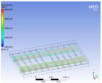
Fig-13 Model 1 (total wall flux)
Fig-14 Model 1 (wall temperature)
Fig-15: Heat flux for Model 4
Fig-16: Heat flux for Model 5
Fig-18: Heat flux for Model 7
IV. Results
Table displaying Ansys simulation results of different models:
density
(kg m^-3)
min max
min max min max min max min max
model 1 368.1 368.2 1.225-1.86E+02 1910 300 368.1 1.26E+01 6.81E+03 300 367.9
model 2 368.1 368.2 1.225-2.61E+03 1.13E+02 300 368.2 2.24E+01 4.91E+03 3.00E+02 3.68E+02
model 3 3.68E+02 3.68E+02 1.225-2.14E+02 5.77E+02 3.00E+02 3.68E+02 2.05E+01 5.88E+03 3.00E+02 3.68E+02
model 4 3.03E+02 3.16E+02 1.225-2.92E+02 5.04E+02 3.00E+02 3.13E+02 3.68E+02 3.68E+02 3.00E+02 3.04E+02
model 5 3.03E+02 3.17E+02 1.225-4.71E+03 -9.70E-01 3.00E+02 3.17E+02 3.68E+02 3.68E+02 3.00E+02 3.04E+02
model 6 3.03E+02 3.17E+02 1.225-1.12E+03 1.16E+03 3.00E+02 3.17E+02 3.68E+02 3.68E+02 3.00E+02 3.05E+02
model 7 3.02E+02 3.15E+02 1.225-2.18E+03 2.20E+03 3.00E+02 3.15E+02 3.68E+02 3.68E+02 3.00E+02 3.03E+02
model 8 3.68E+02 3.68E+02 1.225-5.95E+02 1.21E+02 3.00E+02 3.68E+02 2.11E+01 5.12E+03 3.00E+02 3.68E+02
model 9 3.68E+02 3.68E+02 1.225-7.07E+01 8.61E+02 3.00E+02 3.68E+02 2.07E+01 5.64E+03 3.00E+02 3.68E+02
model 10 3.68E+02 3.68E+02 1.225-5.06E+03 -7.62E-01 3.00E+02 3.68E+02 3.35E+01 3.63E+03 3.00E+02 3.68E+02
model 11 3.68E+02 3.68E+02 1.225-1.31E+02 1.95E+03 3.00E+02 3.68E+02 1.22E+01 8.63E+03 3.00E+02 3.68E+02
model
inner wall
temperature (K)
pressure (Pa)
wall heat flux
(W m^-2)
temperature (K)
temperature (K)
wall adjacen
Fig-19 Analysis simulation results
Graphs comparing Ansys simulation results of different models
Fig-20: graph of inner wall temperature
-6.00E+03 -5.00E+03 -4.00E+03 -3.00E+03 -2.00E+03 -1.00E+03 0.00E+00 1.00E+03 2.00E+03 3.00E+03 m od el 1 m od el 2 m od el 3 m od el 4 m od el 5 m od el 6 m od el 7 m od el 8 m od el 9 m od el 10 m od el 11
pressure (Pa)
pressure (Pa)…Fig-21 Graph of pressure
Modal Analysis 0.00E+00 5.00E+03 1.00E+04 m o… m o… m o… m o… m o… m o… m o… m o… m o… m o… m o…
wall heat flux (W m^-2)
wall heat flux (W m^-2) min wall heat flux (W m^-2) max
0 200 400 m od … m od … m od … m od … m od … m od … m od … m od … m od … m od … m od …
temperature (K)
temperature (K) min temperature (K) max
Fig-23 graph for overall temperature
V. Conclusions VI.
This study presents numerical analysis of effect of various louver fin configurations on heat transfer rate. The three dimensional governing equations for fluid flow and heat transfer are solved using ANSYS Fluent 19.2, fin geometries are developed using Catia v5. Multiple models are included in this study for better understanding of the fin behavior. Total 11 models are designed using Catia and are analyzed using Ansys fluent module. The observations made during the study are discussed below:
1. The thermal behavior of fins is almost similar except for model 4, 5, 6, 7.
2. The variation in the behavior of fin is due to change in turbulence in flow.
3. The heat flux in these models is steady and uniform when compared to other models. 4. Fluxes are highly fluctuating in all models
except in 4,5,6,7.
5. It is evident that by controlling the air flow rate we can govern the heat transfer.
6. Here the performance of the fin is evaluated using lowest temperature recorded and low range of fluxes.
VII. Future Scope
Present study deals with Louver fin performance with Aluminum alloy 6061. At present condensers doesn’t have Louver fins. In this study we added Louver fins to the Radiator. In this thesis it gave the good results for the condensers with louver fins. Experimentation and theoretical analysis is much suggested.
VIII. References
[1] Experimental and CFD study of a single phase cone-shaped helical coiled heat exchanger: an empirical correlation. By Daniel Flórez-Orrego, ECOS June 26-29, 2012.
[2] Numerical And Experimental Studies of a Double pipe Helical Heat Exchanger by Timothy John Rennie, Dept. of Bio-resource Engg. McGill University, Montreal August 2004.
[3] Experimental and CFD estimation of heat transfer in helically coiled heat exchangers by J.S. Jayakumar, S.M. Mahajani, J.C. Mandal, P.K. Vijayan, and RohidasBhoi, 2008, Chemical Engg Research and Design 221-232.
[4] Heat Transfer Optimization of Shell-and-Tube Heat Exchanger through CFD Studies by Usman Ur Rehman, 2011, Chalmers University of Technology. [5] Structural and Thermal Analysis of Heat Exchanger with Tubes of Elliptical Shape by Nawras H. Mostafa Qusay R. Al-Hagag, IASJ, 2012,Vol-8 Issue-3.