Abstract— Traditional static wireless sensor networks suffer mostly from the high latency between the event sensed by a sensor and its reception by a base station. The sensors’ lifetime in the network may influence this latency to the point of being dramatic caused by network partitioning. Current research work is tending towards the optimization of routing mechanisms in order to increase the network's lifetime. Our approach consists in injecting mobile relay nodes whose mission is mainly to maximize the lifetime of the network, to provide connectivity between any sensor and the base station, and obviously to minimize the latency of receiving data sent to the base station. Smart mobility is the key for our approach to ensure reliability by forming a virtual mobile circle using relay nodes. We have proved formally and by simulation the effectiveness of our approach, the obtained results prove the efficiency of our approach.
Index Terms—Mobile relay node; Mobility; Collaboration; Network lifetime; Wireless Sensor Network.
I.INTRODUCTION
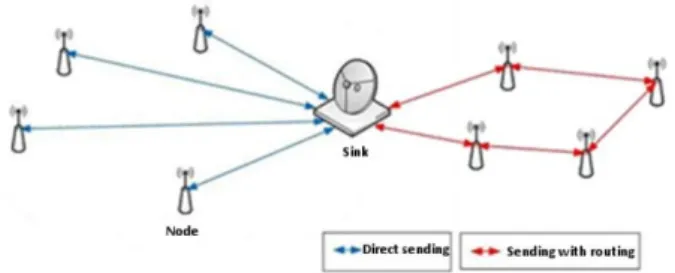
We consider a network of wireless sensors, where each sensor collects data from the environment (eg. temperature). The collected data should be routed to the Base Station (BS) for central processing as shown in Figure 1.
Figure 1. Wireless sensors network.
The problem with this type of scenario is the deterioration of the network’s lifetime since the sensors close to the BS will act as relays to route the captured data by different sensors towards this BS. Over time, their energy will decrease faster than the one of the other sensors and thus, they will be isolated.
To solve this problem, our contribution aims to ensure a reliable exchange and routing of sensed data based on wise management of sensors mobility. In the literature, there is a lot of works that aims to mobilize the BS to collect the data captured by the sensors [1], one of the best proposals is to mobilize the BS on the peripheral of the environment [2].
The authors prove that the duration network life is 500 times better than in a static network.
Moving the BS is an intelligent solution, but this solution introduces the problem of centralization. The central entity (BS) should be protected in a safe place avoiding movements that can affect the content of the collected data. Also, the end-to-end delay will be considerable since the data will only be exchanged when the BS passes through the static sensor. Our contribution proposes to use mobile relay nodes whose role is to collect the data captured by the sensors and route them to the BS.
If we follow the strategy presented in [3] for the deployment of these relay nodes, we will obtain the organization presented in Figure 2, which will lead us to the initial problem: the relay nodes close to the BS will quickly die because they will act as relays to route data to the BS. Also, the movement of the relay nodes varies from a node to another: those near the BS have a slower speed compared to the distant ones.
Figure 2. Relay Nodes Placement proposed in [3]. II.WIRELESSSENSORNETWORKS
Wireless Sensor Network (WSN) is defined as collection of wireless sensors which is deployed in application field and based on the requirement of the data the sensor may differ, i.e., if once the node is deployed, the network is organized. Subsequently, the nodes will collect the data and transmit it to the centralized node (named Base Station ’BS’ or Sink) to process the data as per the user requirement [4].
There are many models of sensors that correspond to different applications needs deploying in a network. Yet they are all mainly composed of three parts in common: The acquisition unit, the processing unit and the transmission unit.
Energy is the critical factor of a sensor network. Indeed, this is a limited resource and crucial because not replaceable. A. Information transmission in a wireless sensor network Transmission of information in a network can be done in two ways:
A New Mobile Collaborative Approach Based
Relays for Wireless Sensor Networks
Guezouli Lyamine, Barka Kamel, Bouam Souheila
University of Batna 2, AlgeriaFigure 3. Information transmission mode in a Sensor Network.
Direct sending: Each node is closely linked to the collection unit, and no intermediary can be involved in this direct privileged link (as it is illustrated by Figure 3 – left part). Sending by ad hoc routing: When nodes are not connected to the collection unit, direct transmissions are not possible, thus routing information rules should be applied (as it is illustrated by Figure 3 – right part).
B. Routing constraints
The Ad hoc routing protocols are not specifically dedicated to wireless sensor networks. Routing in sensor networks must take into account a basic constraint which is energy consumption. Despite the fact that wireless sensor networks are related to ad hoc networks, the specificities, objectives and requirements of such networks can differ.
However, for sensor networks, we can distinguish only few dedicated protocols, which may be classified into four categories: Hierarchical protocols, location- based protocols, data-centric protocols, and consideration of network stream. C. Smart sensors
Smart sensors are hardware devices including the sensor, processing and communication circuits. Their relation with higher processing layers extends well beyond a simple signal transmission. The most followed approach to realize a smart sensor is that combining the measure function with the information processing function. This is exactly what is achieved when the device incorporates a microprocessor perception. The treatment algorithm used in this case is programmable and can be changed later (development, adaptation, redesign ...) [5].
D. Energy dissipation in a sensor
Given the diversity of the sensors, there are no typical values of the energy consumed. On the other hand, passive sensors (temperature, seismic ...) often consume less energy than other sensor nodes. Note that active sensors such as sonars and image sensors can consume much more energy. In addition, there are other forms of energy dissipation such as readings and memory writes.
It is difficult to provide here a precise quantitative and comparative study of each sensor node consumption due to the large number of existing commercial platforms. However, experiments have shown that data transmission is the most energy consuming. The cost of transmitting one bit of information is approximately the same as the cost required to calculate 1,000 transactions [6]. The consumption of the detection module depends on the specific type of the sensor node.
III.PURPOSEOFMOBILITYINWSNS
The architectures of traditional WSNs are based on the
assumption that the network is dense, so that two nodes can communicate with each other through a multi-hop communication. Therefore, in most cases sensors are considered static and mobility is not considered an option. More recently, similar to the trend of research in Mobile Ad-hoc NETworks (MANET) [7] and Delay-Tolerant Networks (DTNs) [8], mobility was also introduced in the WSNs ([9], [10]). In fact, mobility in WSNs is useful for several reasons ([11], [12], [13], [14]), as described in the following: A. Connectivity
Because nodes are mobile, a dense WSNs architecture may not be a requirement. In fact, the mobile elements can relate the isolated regions, so that the connectivity constraint of the network is relaxed. Thus, a scattered WSN architecture becomes a realistic option.
B. Cost
By deploying fewer nodes in a WSNs with mobile elements, the cost of the network is reduced, however the addition of mobility features to nodes can be expensive, in many cases it is possible to exploit mobile elements which are already present in the area (eg trains, buses, shuttles, or cars), and attach them sensors.
C. Reliability
Since traditional static WSNs are dense and the communication paradigm is often multi-hop, reliability is compromised by interference and collisions. In addition, message loss increases with a high number of jumps. The mobile elements visit the nodes in the network and retrieve the data directly via one-hop transmissions. This reduces not only conflicts and collisions, but also messages loss. D. Energy efficiency
The inherent traffic model in WSNs is the ConvergeCast that means the messages are generated from the sensor nodes and are collected by the Sink. Consequently, the nodes closest to the Sink are overloaded compared to the others, and therefore exhaust their energy prematurely. This problem is known as Funneling Effect because the neighbors of the Sink represent the traffic bottleneck. Moving elements, called mobile relay nodes can help to reduce Funneling effect phenomena because they can visit different regions of the network and propagate energy consumption more evenly, even in the case of a WSN with dense architecture.
IV.CHARACTERISTICSANDCONSTRAINTSOF WSNS
A. Network lifetime
This is the time interval between the moment of network deployment and the moment when the energy of the first node is depleted. Depending on the application, the required life time of a network can vary from a few hours to several years.
B. Limited bandwidth
C. Transportation Media
In a sensor network, multi-hop communication between nodes is achieved with wireless links using optical, infrared or radio media. Most sensor networks use radio frequency communication circuits due to their low cost and ease of installation.
D. Network topology
It is in constant evolution due to the changing state of sensor activity (active, sleep and passive). Sensors must be able to adapt their operation to maintain the desired topology. E. Deployment
Sensors are either deterministically distributed or randomly deployed (from an aircraft, for example).
F. Scaling
Most protocols are designed for large sensor networks. However, these protocols are said to be effective if network performance is not to drop drastically as the number of sensors in the network increases.
G. Energy consumption
Saving energy is one of the major issues in sensor networks. Indeed, recharging energy sources is often too expensive and sometimes impossible. It is therefore necessary that the sensors save as much energy as possible in order to operate. H. Self-configuration
Sensor networks are generally deployed randomly in areas of hostile interest. Therefore, no human intervention may be required to ensure their organization. Self-configuration of these networks is necessary for their proper functioning. I. Dynamic topology
Sensors can be attached to moving objects that move freely and arbitrarily and the change of state of the sensors between active and sleep mode makes the network topology frequently change.
V.RELATEDWORKS
Despite the many applications of WSNs, these networks have several constraints in terms of energy, computation and bandwidth. The main objective of such networks is to provide communications and data collection between the wireless sensors and the Sink, while attempting to extend the network lifetime and to avoid problems of bottlenecks resulting from the approaches which can severely degrade network performance. There are several reasons why mobile nodes should be used compared to static nodes, such as improving network performance.
It is for these reasons that mobility in the WSNs is a great importance topical subject and a center of many researcher’s interest. The methods proposed until nowadays, according to the nature and the number of mobile nodes used [15-17], can be classified into two main categories: methods based Sink mobility and methods based relay nodes mobility.
A. Methods based sink mobility
For methods based Sink mobility [1], The authors in [18] are interested in networks of sensors operating at different sampling rates and propose a solution to schedule the sink movement so that each node is visited - possibly several times – before it experiment data loss due to buffer overflow.
The authors in [19] propose a Sink-based approach. The Sink broadcasts an interest message to neighboring sensor nodes by moving on a straight line. The sensor nodes receive the interest message and transmit it to their own neighbors. Each sensor node begins transmitting the data to the mobile Sink when an event occurs. The mobile sink is out of range during the event transmission and therefore the packets will be lost. The solution uses acknowledgments to ensure that the Sink has received the packet successfully, and a sensor node transmits other packets only after it has received an acknowledgment from the Sink.
The authors in [20] consider a static sensor network with multiple mobile sinks, where every node has to take the decision whether to transmit or not its collected data when a sink is in its vicinity, based on its buffer occupancy, its Euclidean distance to the sink or an history of previous occasions.
The authors in [21] proposed a novel mechanism that adopts unmanned aerial vehicles (UAV) to gather data from forest regions instead of classical sensing from nodes deployed in WSN. The proposed method enables the UAV to collect data from WSN in harsh terrain and transmit it to the base station situated far from the sensing area. Therefore, the multi-hop transmission between cluster heads can be completely avoided, and the communication range can be extended. With a similar vision, authors in [22] design and implement a strategy to regulate load while also improving the energy efficiency of the network. Each node has a threshold level of the load beyond which if there is inflow of data then the node automatically sends a message requesting for aid from the mobile collector (MC). Based on the requests received from all the nodes, the MC estimates the most suitable position to move to among a bunch of static WSNs deployed to monitor and agricultural area.
In [23], authors proposed a hybrid mobile sink combining (PEGASIS)-based routing protocol with a direct transmission (MIEEPB-DT) protocol. The objective is to improve the lifetime of WSNs and to mitigate the energy hole issue. The proposed protocol is suitable for delay-tolerant and delay-indelay-tolerant applications. The basic concept of the proposed protocol is to divide the entire area into a small zone, to divide each zone into a close sub-region and a far sub-region, and to create a chain in each region. This decreases the overhead of the network due to fewer nodes in the chain and decreases the gap between the linked nodes across the chain.
In [24], a new optimal sink node placement is proposed to enhance the network lifetime and packet delivery ratio of WSN. The method is suggested in which zone structure, along with regulated sink mobility, is favored for the mitigation of energy holes and optimum positioning of sink nodes. In ZBSM, the sink chooses to switch into a highly loaded zone (SLZ) to prevent network partitioning problems where the SLZ selection can be done using Fuzzy Logic. Performance findings indicate that the new scheme decreases energy usage and increases the existence of the network relative to the current scheme.
B. Methods based relay nodes mobility
one-hop routing (from the sensor to the "Mule" directly) instead of a more expensive multi-hop routing (from the sensor to the Sink).
The authors in [26] looked at the performance of a dense network with a mobile relay node and showed that the lifetime of the nodes in the network increased. Communication involving relay nodes in all approaches considers two scenarios: from single sensor to a relay and from relay to a Sink. The relay to relay communication that could potentially be useful is neglected. According to the authors, no work has examined the advantages of allowing communication between data collection nodes to form a network.
In the work [27], authors are interested in applying a variant of the mobility model RWP (named routing-random waypoint 'R-RWP') on the whole network in order to maximize the coverage radius of the base station (each node that is in the coverage of the BS is considered to be a relay for other nodes that are far from this BS) and thus to optimize the data delivery end-to-end delay.
The authors in [28] have decided to integrate their approach to reporting vehicles in traffic, the vehicles here will be considered as relays, and they provide intelligent mobility as part of a route perception strategy. In addition, they have shown that even a complex behavioural model can be represented using realistic simulation studies. The objective of the study is to update the OLSR (Optimized Link State Routing) protocol. Obviously, by providing an appropriate process, such routing mechanism could be helpful in exchanging control messages.
In [29], The suggested algorithm preserves clustering on the
mobile network and saves the overhead of re-clustering. The proposed algorithm clusters the network initially based on distance of nodes from the sink. Nodes closest to the sink are chosen as cluster heads. In case of unreachable sink, re-clustering is required. It works with the assumptions that all nodes have GPS and are aware of their remaining energy. Mobile relay node has more energy and computational power. CHs have information of their member nodes. This is intended to have improved system functionality and performance.
In [30], in order to improve the energy efficiency of hierarchical WSNs, the authors use MU-MAB technology to solve the problem of relay selection. They developed a CH selection mechanism with a mobile sink (MS) while proposing multi-user multi-armed bandit (UM-MAB) relay selection algorithms to solve the energy efficiency problem. In addition, they use a robust matching principle focused on marginal utility for the distribution of the final one-to-one optimum combinations to achieve energy output.
VI.CONTRIBUTION-SYNCHRONIZED
COLLABORATIONMOVEMENTBETWEENMOBILE
RELAYS
For the reasons cited above, we propose a specific organization of theses relay nodes to get them mobilized without affecting the energy of a static sensor to the detriment of another. We propose the organization presented in Figure 4(a). Each mobile relay node has a coverage field as shown in Figure 4(b).
Figure 4. (a) Relay nodes Initial disposition in our approach & (b) Mobile relay node coverage.
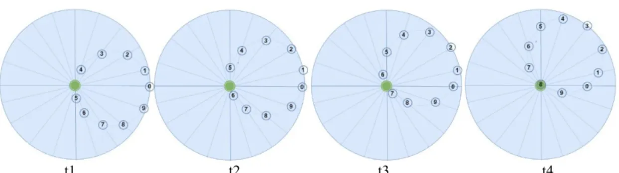
t1 t2 t3 t4
Figure 5. Relays nodes synchronized movement, each in its linear trajectory thus forming a mobile virtual circle (t1,t2,t3,…).
The synchronized movement of the relay nodes will
With this solution, we guarantee that the energy consumed by the relay nodes will be equitable. This significantly extends the whole network lifetime, providing a reliable environment for transferring data from the environment to the BS.
We will then formally validate our approach. A. Preliminary
1) Radius of the Analysis Area (R)
As a first step we have defined a variable R which represents the radius coverage of the observation area, in order to be able using this variable in the following equations sequences.
2) Mobile Relay Coverage Area (Ca)
Each mobile relay has a coverage area which is calculated by
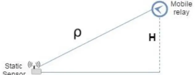
𝐶𝑎= 2(𝜌 + √𝜌2− 𝐻2) (1)
Where:
ρ : The range of a static sensor ;
H: The vertical distance (height between the relay and the sensor – Figure 6).
Figure 6. The distance ‘H’ between the relay node and the static sensor.
3) Minimum Range of the Mobile Relay (r)
The minimum range of the mobile relay is formulated by
𝜌𝑟= 𝑅 × 𝜋
𝑁𝑟 (2)
Where:
Nr : is a sufficient number of relays performing our virtual mobile circle (We define this parameter in (7)). B. formulas of the virtual mobile circle
1) Relay Motion
The mobility of each node in a linear trajectory is a simple harmonic oscillator (i.e., simple harmonic motion), according to (3) that represents a differential equation of the second degree
𝑥̿ + 𝑤2𝑥 = 0 (3)
With: w, is the pulsation;
Solving this differential equation (3), we find that the motion is described by the function
𝑥(𝑡) = R ∗ cos(2𝜋
𝑇 ∗ 𝑡 + ∅) (4)
With:
T: is the Period of oscillation;
R: represents the peak amplitude of oscillation (analysis area Radius);
∅: represents the phase shift. We assume at time t0 the
relay is positioned at the observation area center (with the BS), for this ∅ = 0.
In space, (4) becomes
{
𝑥(𝑡) = 𝑅 ∗ cos(𝛽) ∗ cos(2𝜋
𝑇 ∗ 𝑡)
𝑦(𝑡) = 𝑅 ∗ sin(𝛽) ∗ cos(2𝜋
𝑇 ∗ 𝑡)
𝑧(𝑡) = 𝐶
(5)
With C = R ∗ π Where:
C : Circle perimeter with C ≤ H t : The time
𝛽 : is the angle between the relay trajectory and the x-axis 2) Relay Speed
To calculate the speed of the relays we use the following formula:
𝑉(𝑡) = −𝑅 ∗2𝜋
𝑇 ∗ sin(
2𝜋
𝑇 ∗ 𝑡) (6)
3) Detection Time ‘Relay – BS’ and ‘Relay – Sensor’ The maximum time for a mobile relay to re-detect the BS is ≈ T/2 and the maximum time for a static sensor to re-detect the same mobile relay is ≈ T
Noted that the maximum time is related to the static sensors located at the area edge. However, for those close to the BS this time decreased gradually. 4) Virtual Circle Construction Mechanism by Relays In order to create a virtual circle of the mobile relays based on their linear movements; we must firstly calculate the sufficient number of relays to cover the entire observation area, after that these relays must have a predefined deployment and be synchronized between them.
• Relays number:In order to collect the data from the static sensors in the analysis area, it is necessary to have a sufficient number of relays performing this function. Therefore the number of relays is calculated by
𝑁𝑟=
𝜋𝑅
2(𝜌 + √𝜌² − 𝐻²) (7)
𝛼 = 𝜋
𝑁𝑟 (8)
Each relay ‘I’ moves according to (5). With the angle 𝛽 = 𝛼* I (I : The relay index) However, the synchronization between movements is important.
• Relays synchronization: In our proposal the synchronization time factor between the relays is very important and is calculated by
𝑆𝑦𝑡= 𝑇
2 ∗ 𝑁𝑟 (9)
5) Data Routing via Relays
The proposed routing mechanism is defined as follows: If a static sensor node detects the BS in its coverage area, it sends its data directly without passing through the mobile relay.
Else, the static sensor will keep its collected data in its memory, and will send it to the first mobile relay that it detects (to avoid data redundancy at the BS). Once the data eaches the mobile relay, it forwards this data to the BS directly if detecting there in its neighbors (one-hop), else by multi-hops collaboration with its neighbors relay mobile.
Each relay will be able to route the data to the BS through two paths, either through the left neighbors or through the right ones. To select the shortest route to the BS, the relay will change alternately the sending direction each time it detects the BS (Figure 7).
Figure 7. The send direction to the BS.
VII.PERFORMANCEOFOURSYNCHRONIZED COLLABORATIONPROPOSAL
We have projected the different mathematical formulas of our approach under the CupCarbon simulator [12], according to the parameters shown in Table 1.
We assume that the environment is without any obstacles during the entire duration of simulation. At the beginning of each simulation; the simulated WSN consists of 100 static sensors, deployed in an observation area with a radius of 100 meters and each static sensor’s communication range is 10 meters. For the mobile relays, the range of the mobile relay is 35 meters, and we define the vertical distance between the relay and the sensor as 8 meters.
Table 1. Simulation parameters
Parameter Value
Number of static sensors 100
𝑅 100 m
𝜌 10 m
𝜌𝑟 35 m
𝐻 8 m
These parameters represent all that is necessary to have the following results.
A. Relay Redundancy
To avoid sending redundant data by static sensors, it is necessary to set up an index for each relay I ∈ [0, Nr− 1] . In the case where a sensor detects two relays at the same time in its sensor field, it sends its data to the relay which has the minimum index. B. Alive Nodes Number
If we take into account only the energy consumed by the static sensors, we maintain that the lifetime of a sensor is very significant since, with our approach, we have avoided the mutli-hop from which a minimum consumption is required by a sensor. More preferably, the energy consumed is fair on all the static sensors constituting the network. For all these reasons, the live nodes average is prolonged significantly.
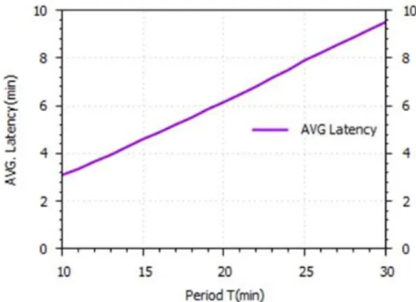
C. Reception Latency
Figure 8 shows that the latency is affected by the time of a phase traversed by a mobile relay. Indeed, a static sensor must wait the mobile relay to send him his captured data. This waiting time will be important depending on the mobile relay speed to traverse a movement phase.
Figure 8. Average Latency.
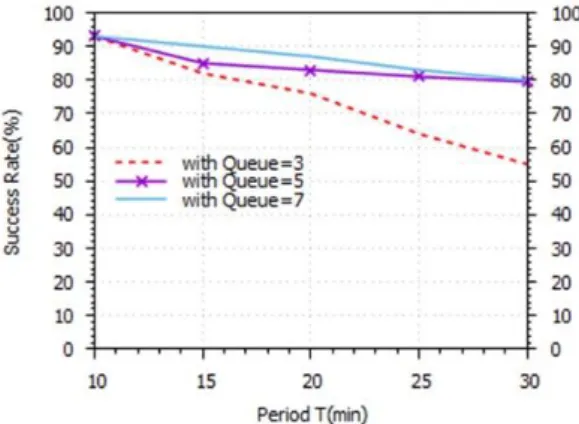
D. Sent Packets Success Rate
It is assumed that for 5 minutes each node detects an event and calculates the percentage of the packets number arriving at the BS in relation to the number of packets that occur, during the simulation time (30 minutes) under the following configuration (T = 10 15 20 25 30). The simulation results are shown in Figure 9
shows the close relationship between this success rate and the queue size.
From Figure 8 and Figure 9, the choice of period mostly affects the results, such that if the network has a very active state (many of the events are triggered) and the period is large, in this case a risk of data loss is to be expected. And vice versa, if the network will present a stationary state (rare trigger of an event) and the period is small, in this case the relays consume their energies without interest. So, we will need a mechanism that adjusts the period according to the state of the environment.
Figure 9. Sent packets success rate.
E. Sufficient relays for event area coverage
In order to validate equation N°7, we carried out a simulation to conclude the number of relays necessary to ensure coverage of the entire event area. The simulation results are shown in Figure 10. What attracts our attention is that with our approach we can reduce the required relays’ number relative to the size of the event area.
Figure 10. Sufficient relays’ number for event area coverage.
VIII.CONCLUSION
When establishing the state of the art, we distinguished the scenario where the network is static, where the energy problem is critical and leading to a minimal network lifetime. On the other side, when mobility is integrated, especially in the scenario where the BS moves and captures the data from the sensors, the energy saving is partially enhanced compared to the static approach, but two basic issues remain: the energy loss and the security which will be difficult to
ensure because of BS mobility. In our approach, we proved that the lifetime is optimal; because only relays are moving, that means that the energy consumption in our network is fairly and wisely shared between all members of the network.
Our approach guarantees network connectivity, since we have a link between the static sensors and the BS across the relay nodes. The virtual mobile circle ensures optimization of the sending latency. Indeed, a data sensed by a sensor will be transferred through this circle, and from a relay to another data will be transferred until reaching the BS. Our solution is highly effective if used in Agricultural monitoring. The fault tolerance of mobile relays is our current problematic; we are trying to find the right compromise between the required nodes number upon deployment to guarantee a good level of fault tolerance.
REFERENCES
[1] Y. Gu, F. Ren, Y. Ji, and J. Li, "The evolution of sink mobility management in wireless sensor networks: A survey," IEEE Communications Surveys & Tutorials, vol. 18, pp. 507-524, 2016.
[2] J. Luo and J.-P. Hubaux, "Joint mobility and routing for lifetime elongation in wireless sensor networks," in INFOCOM 2005. 24th annual joint conference of the IEEE computer and communications societies. Proceedings IEEE, 2005, pp. 1735-1746. [3] W. Wang, V. Srinivasan, and K.-C. Chua,
"Using mobile relays to prolong the lifetime of wireless sensor networks," in Proceedings of the 11th annual international conference on Mobile computing and networking, 2005, pp. 270-283.
[4] T. Ojha, S. Misra, and N. S. Raghuwanshi, "Wireless sensor networks for agriculture: The state-of-the-art in practice and future challenges," Computers and Electronics in Agriculture, vol. 118, pp. 66-84, 2015. [5] J. Rice, K. Mechitov, S.-H. Sim, B. Spencer
Jr, and G. Agha, "Enabling framework for structural health monitoring using smart sensors," Structural Control and Health Monitoring, vol. 18, pp. 574-587, 2011. [6] G. J. Pottie and W. J. Kaiser, "Wireless
integrated network sensors," Communications of the ACM, vol. 43, pp. 51-58, 2000.
[7] W. Zhao, "Proactive routing in highly-partitioned wireless and ad hoc networks," in proc of 9^< th> IEEE Workshop on Future Trends in Distributed Computing Systems (FTDCS) May, 2003, 2003.
Applications, technologies, architectures, and protocols for computer communications, 2003, pp. 27-34.
[9] R. Shah, S. Roy, S. Jain, and W. Brunette, "Data mules: modeling a threetier architecture for sparse networks," Ad hoc Networks, vol. 1, pp. 215-233, 2005. [10] R. Silva, J. S. Silva, and F. Boavida,
"Mobility in wireless sensor networks– survey and proposal," Computer Communications, vol. 52, pp. 1-20, 2014. [11] A. Kansal, A. A. Somasundara, D. D. Jea, M.
B. Srivastava, and D. Estrin, "Intelligent fluid infrastructure for embedded networks," in Proceedings of the 2nd international conference on Mobile systems, applications, and services, 2004, pp. 111-124.
[12] G. Anastasi, M. Conti, M. Di Francesco, and A. Passarella, "Energy conservation in wireless sensor networks: A survey," Ad hoc networks, vol. 7, pp. 537-568, 2009.
[13] S. R. Gandham, M. Dawande, R. Prakash, and S. Venkatesan, "Energy efficient schemes for wireless sensor networks with multiple mobile base stations," in Global telecommunications conference, 2003. GLOBECOM'03. IEEE, 2003, pp. 377-381. [14] G. Wang, G. Cao, T. La Porta, and W. Zhang,
"Sensor relocation in mobile sensor networks," in INFOCOM 2005. 24th Annual Joint Conference of the IEEE Computer and Communications Societies. Proceedings IEEE, 2005, pp. 2302-2312.
[15] M. Conti, A. Passarella, and L. Pelusi, "Mobile-relay forwarding in opportunistic networks," in Chapter in Adaptive Techniques in Wireless Networks (M. Ibnkahla, Editor, 2008.
[16] I. Chatzigiannakis, A. Kinalis, and S. Nikoletseas, "Sink mobility protocols for data collection in wireless sensor networks," in Proceedings of the 4th ACM international workshop on Mobility management and wireless access, 2006, pp. 52-59.
[17] M. Di Francesco, S. K. Das, and G. Anastasi, "Data collection in wireless sensor networks with mobile elements: A survey," ACM Transactions on Sensor Networks (TOSN), vol. 8, p. 7, 2011.
[18] Y. Gu, D. Bozdag, E. Ekici, F. Ozguner, and C.-G. Lee, "Partitioning based mobile element scheduling in wireless sensor networks," in Sensor and Ad Hoc Communications and Networks, 2005. IEEE SECON 2005. 2005 Second Annual IEEE Communications Society Conference on, 2005, pp. 386-395.
[19] C. Intanagonwiwat, R. Govindan, and D. Estrin, "Directed diffusion: A scalable and
robust communication paradigm for sensor networks," in Proceedings of the 6th annual international conference on Mobile computing and networking, 2000, pp. 56-67. [20] D. Turgut and L. Bölöni, "Heuristic approaches for transmission scheduling in sensor networks with multiple mobile sinks," The Computer Journal, vol. 54, pp. 332-344, 2011.
[21] P. Mathur, R. H. Nielsen, N. R. Prasad, and R. Prasad, "Data collection using miniature aerial vehicles in wireless sensor networks," IET Wireless Sensor Systems, vol. 6, pp. 17-25, 2016.
[22] T. F. Khan and D. S. Kumar, "Mobile collector aided energy reduced (MCER) data collection in agricultural wireless sensor networks," in Advanced Computing (IACC), 2016 IEEE 6th International Conference on, 2016, pp. 629-633.
[23] A. Rady, M. Shokair, E.-S. M. El-Rabaie, W. Saad, and A. Benaya, "Energy-efficient routing protocol based on sink mobility for wireless sensor networks," IET Wireless Sensor Systems, vol. 9, pp. 405-415, 2019. [24] A. Prasanth and S. Pavalarajan, "Zone-based
sink mobility in wireless sensor networks," Sensor Review, 2019.
[25] R. C. S. S. R. Sushant, "Data mules: Modeling a three-tier architecture for sparse sensor networks," in the 2nd ACM International Workshop on Wireless Sensor, 2003.
[26] W. Wang, V. Srinivasan, and K.-C. Chua, "Extending the lifetime of wireless sensor networks through mobile relays," IEEE/ACM Transactions on Networking (TON), vol. 16, pp. 1108-1120, 2008. [27] L. Guezouli, K. Barka, S. Bouam, and A.
Zidani, "A variant of random way point mobility model to improve routing in wireless sensor networks," International Journal of Information and Communication Technology, vol. 13, pp. 407-423, 2018. [28] Y. Hernafi, M. B. AHMED, and M.
BOUHORMA, "Smart Mobility and Driver Behavior correlated with Vehicular Networks under a Social Perception in Smart Cities," International Journal of Information Science and Technology, vol. 2, pp. 35-47, 2019. [29] N. Gupta and S. Jain, "Dynamic Relay
Assisted Clustering in WSN," in 2018 Global Wireless Summit (GWS), 2018, pp. 33-36. [30] J. Zhang, J. Tang, and F. Wang, "Cooperative
![Figure 2. Relay Nodes Placement proposed in [3].](https://thumb-us.123doks.com/thumbv2/123dok_us/8079062.2140421/1.892.89.415.714.928/figure-relay-nodes-placement-proposed.webp)