Accelerometer Based Vehicle Monitoring And Tracking System Using
ARM Processor And GPS
B.Praveen kumar, V.Anuragh, NLP Raju M.Tech scholar, Assistant Professor,
DEPT of ECE,
BVC ENGG COLLEGE, Odalarevu.
Abstract— This paper mainly deals with concept of Vehicle tracking, Monitoring and providing security by theft. This system is based on ARM7, GSM and GPS is proposed. GSM technology is used to send information about the vehicle by using GPS receiver, information contains location, speed, temperature of vehicle and control message to stop the vehicle in case of theft. ARM7 TDMI-S core processor with LPC 2148 microcontroller collects the information and sends to the Monitoring system using GSM modem. The Monitoring system uses GUI to display the received information. GUI is developed by using Visual Studio 2010. The Monitoring system can turn OFF the vehicle engine by using relays in case of theft.
Keywords- ARM7 TDMI-S, LPC2148, GPS Modem, GSM, Accelerometer.
I. INTRODUCTION
In present days as population increases the number of vehicles also increases. This results in more accidents and deaths and also theft [1]. The result of this system saves death or reduces the death rates, by providing information about the accident to the Monitoring system immediately.
A server computer at the (remote) monitoring station that is continuously waiting for data from the system should record the actions of the vehicle into a database. This contains the information regarding Vehicle velocity, position, identity and temperature in two fashions. The information given to monitoring station is in continuous manner and when the accident occurs. The development of vehicular design brings public many convenience in life but also brings many problems at the same time, for example, traffic congestion, difficulty in monitoring dispersive vehicle, theft and other series of problems[4].We are intended to made this monitoring wireless using ARM7 hardware platform ported with real time operating system µc/OS-II.
It improves the level of management in buses of travel agencies and cargo transportation vehicles, such as trucks [2].
It also provides security to personal vehicles like car by locking the vehicle engine from remote location using GSM in case of theft [3]. A Monitoring system continuously waits for information sent from vehicle system. The information sent by the vehicle system includes position of a vehicle (Longitude and Latitude), speed and temperature. The information provided to the Monitoring system when accident happens or when user accesses the system to get the information about the vehicle.
Key feature of this design include:
a) User can access the system to get the information about vehicle at any time whenever needed.
b) Vehicle system will send the information about vehicle automatically to Monitoring system. This results in medical help in case of accident and in case of theft.
c) User can stop the vehicle engine, whenever theft of vehicle by using relays.
d) It includes a temperature sensor that gives temperature in degree Celsius for monitoring the environmental conditions around the goods or other stuff in the transport vehicle.
II. ESSENTIAL HARDWARE OF VEHICLE SYSTEM
1. ARM7 TDMI-S LPC2148 controller 2. GPS Receiver MT 3318
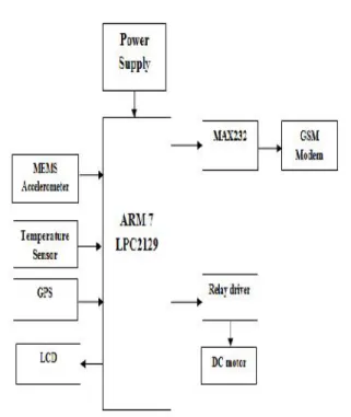
Fig 1: Block diagram
1. Micro controller unit
Micro controller, this section forms the control unit of the whole project. This section basically consists of a Microcontroller with its associated circuitry like Crystal with capacitors, Reset circuitry, Pull up resistors (if needed) and so on. The Microcontroller forms the heart of the project because it controls the devices being interfaced and communicates with the devices according to the program being written. ARM7TDMI: ARM is the abbreviation of Advanced RISC Machines, it is the name of a class of processors, and is the name of a kind technology too. The RISC instruction set, and related decode mechanism are much simpler than those of Complex Instruction Set Computer (CISC) designs.
The vehicle system contains hardware peripherals like, ARM7 TDMI-S Core processor, pressure sensor, temperature sensor, accelerometer, GPS MT 3318 receiver, DC Relay, 16×2 LCD, SD memory card, GSM modem and power supply.
The temperature sensor provides temperature per degree Celsius to an ARM7 processor. The temperature sensor is interfaced to an ADC1 of ARM7 processor. Vehicle speed, position and temperature are stored in a SD card. The SD card is interfaced to an ARM processor by using SPI (Serial Peripheral Interface). This information is shown on LCD that is interfaced to a GPIO0 and sends it to a Monitoring system (receiver side) by GSM module
wirelessly that is interfaced to a UART0 of ARM processor.
Features of ARM7 TDMI-S LPC2148:
• ARM7 TDMI–S LPC2148 microcontroller with 512 Kbyte program Flash and 32+8 Kbyte SRAM.
• 16/32-bit ARM7TDMI-S microcontroller in a 64 or 144 pin package.
• 32.768 kHz RTC crystal. • Onboard Peripherals
- 2x16 character LCD with background light - Joystick switch
- UART-to-USB bridge interface on UART #0
- USB 2.0 device interface
- RGB-LED, each color can be controlled via PWM Signal.
- 8 LEDs
- Temperature sensor (LM75) on I2C bus - Pushbutton on P0.14 (interrupt input) - 8x8 LED matrix, controlled via shift
registers in the SPI bus
- MMC/SD memory card interface - Step motor (bipolar driving) • 60 MHz maximum CPU clock
available from programmable on-chip Phase-Locked Loop.
• Dual power supply
- CPU operating voltage range of 1.65V to 1.95V (1.8V +/- 8.3%).
- I/O power supply range of 3.0V to 3.6V (3.3V +/-10%).
• System Programming (ISP) and In-Application Programming (IAP) via on-chip boot-loader software. Flash programming takes 1 ms per 512 byte line. Single sector or full chip erase takes 400 ms.
2. GPS MODEM
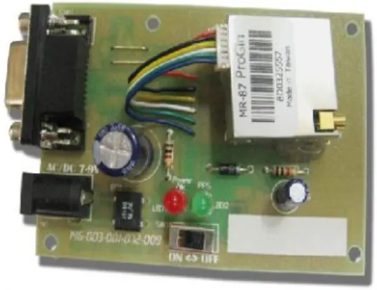
Fig 2: GPS modem
A GPS receiver calculates its position by precisely timing the signals sent by GPS satellites high above the Earth. Each satellite continually transmits messages that include
the time the message was transmitted precise orbital information (the ephemeris) the general system health and rough orbits
of all GPS satellites (the almanac).
The receiver uses the messages it receives to determine the transit time of each message and computes the distance to each satellite. These distances along with the satellites' locations are used with the possible aid of depending on which algorithm is used, to compute the position of the receiver. This position is then displayed, perhaps with a moving map display or latitude and longitude; elevation information may be included. Many GPS units show derived information such as direction and speed, calculated from position changes.
Three satellites might seem enough to solve for position since space has three dimensions and a position near the Earth's surface can be assumed. However, even a very small clock error multiplied by the very large speed of light, the speed at which satellite signals propagate— results in a large positional error. Therefore receivers use four or more satellites to solve for the receiver's location and time. The very accurately computed time is effectively hidden by most GPS applications, which use only the location. A few specialized GPS applications do however use the time; these include time transfer, traffic signal timing, and synchronization of cell phone base stations.
3. GSM MODEM
Global System for Mobile communication. This
GSM Modem can accept any GSM network operator SIM card and act just like a mobile phone with its own unique phone number. Advantage of using this modem will be that you can use its RS232 port to communicate and develop embedded applications. Applications like SMS Control, data transfer, remote control and logging can be developed easily.
This GSM modem is a highly flexible plug and play quad band GSM modem for direct and easy integration to RS232 applications. Supports features like Voice, SMS, Data/Fax, GPRS and integrated TCP/IP stack.
This system uses SIM 300 GSM module in text mode. This system uses SIM300 GSM module that provide 900/1800/1900MHz Tri-band for VOICE, SMS, DATA, and FAX. This module is operates on AT command. AT command is an abbreviation for Attention command that is recognized by GSM Module. "AT command set for GSM Mobile Equipment” describes the Main AT commands to Communicate via a serial interface with the GSM subsystem of the phone. The GSM modem is interfaced to microcontroller through UART0 serial communication.
Examples of AT commands:
Table 1: AT Commands
Architecture of the GSM Network:
In a GSM network, the user terminal is called a mobile station. A mobile station is made up of a SIM (Subscriber Identity Module) card allowing the user to be uniquely identified and a mobile terminal. The terminals (devices) are identified by a unique 15-digit identification number called IMEI (International Mobile Equipment Identity). Each SIM card also has a unique (and secret) identification number called IMSI (International Mobile Subscriber Identity). This code can be protected using a 4-digit key called a PIN code.
Command Description
AT Check if serial interface and GSM modem is working
ATA Answer an incoming call
ATD><MEM><N>
Originate call to phone number in
memory
The SIM card therefore allows each user to be identified independently of the terminal used during communication with a base station. Communications occur through a radio link (air interface) between a mobile station and a base station.
Fig 3: GSM Modem
4. RELAY
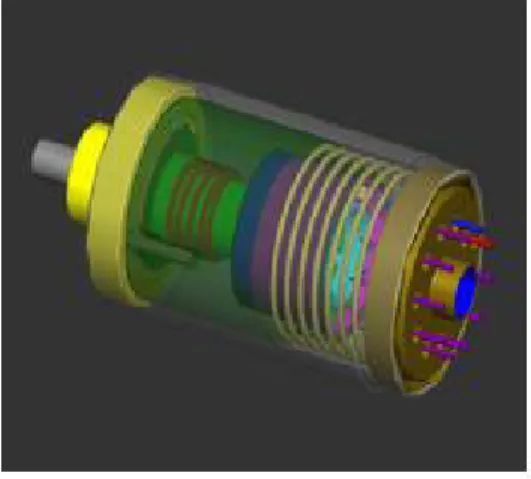
The relay is an electromagnetic switch. When relay is activated, then it closes the loop of ignition, hence start the Engine. When relay is de-activated, it opens the loop of ignition, hence stop the ignition of the automobile.
Fig 4: Electromechanical Relay
5. Accelerometer
Accelerometer measures acceleration. Acceleration is the time rate of change of velocity. This means how quickly changes speed. The measurement of acceleration is used as an input into some types of control systems. Accelerometer sensor is used to measure static (earth Gravity) or dynamic acceleration in all three axes, forward/backward, left/right and up/down. The output of accelerometer provides 1.65V to 3.3V in positive direction and in negative direction the voltage drop from 1.65V to 0V. The output of accelerometer is in analogue form with three different output voltages each representing X, Y and Z direction of motion. These three voltage signal are processed through ADC0 on three different Channels available on ARM.
Fig. 5: Accelerometer
An accelerometer measures proper acceleration which is the acceleration it experiences relative to freefall, and is the acceleration that is felt by people and objects. Put another way, at any point in space time the equivalence principle guarantees the existence of a local inertial frame, and an accelerometer measures the acceleration relative to that frame.
Modern accelerometers are often small micro electro-mechanical systems (MEMS), and are indeed the simplest MEMS devices possible, consisting of little more than a cantilever beam with a proof mass (also known as seismic mass). Damping results from the residual gas sealed in the device. As long as the Q-factor is not too low, damping does not result in a lower sensitivity.
III. MONITORING SYSTEM
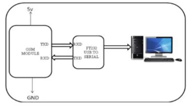
Fig 6: Interfacing of GSM module with PC
IV. SOFTWARES USED
a) Kiel µvision4 IDE:
KeilμVision4 IDE (Integrated Development Environment) is based on windows front end for the C Compiler and assembler. KeilμVision4 is used to write embedded C programs. Embedded C is a high level language, which includes many aspects of the ANSI (American National Standard Institute) C programming language.
b) GUI:
The GUI for the proposed system is designed on Visual Studio 2010. C # is a simple, modern, object-oriented, and type-safe programming language. Microsoft’s C# compiler for the .NET Framework is a conforming implementation of both of these standards. Exception handling provides a structured and extensible approach to error detection and recovery. Also this language is compatible with all Microsoft applications.
c) µc/OS-II
µC/OS-II is a real time operating system that is portable, ramble, scalable, preemptive, real-time deterministic
Multitasking kernel for microprocessors, microcontrollers and DSPs. µ C/OS-II manages up to 250 applications
Tasks (3). RTOS can be ported to ARM hardware, and then the system can deal with much more complicated tasks. Real-time (RT) indicates an expectant response or reaction to an event on the instant of its evolution. And Operating
System (OS) is a system program that provides an interface between hardware and application programs. The µc/OS-II is used for timing constraints.
An Operating system (OS) is nothing but a collection
of system calls or functions which provides an interface between Hardware and application programs. RTOS is key to many embedded systems and provides a platform to build applications. All embedded systems are not designed with RTOS. Embedded systems with relatively simple/small hardware/code might not require an RTOS.
V. WORKING SYSTEM
The entire vehicle system is installed in the vehicle as shown in below figure and Monitoring system at remote location. The entire system works in the following cases.
Fig 7: Complete model of a system.
Fig.8: Monitoring systems at remote locations
Second case is, when user wants to access the system to know the vehicle information, the user will send request message to the Vehicle system from Monitoring system through GSM modem. The GSM modem at Vehicle system receives user request and verifies, if in-valid discards the message, otherwise forwards message to the microcontroller. The microcontroller collects the necessary information from different peripherals and sends back to the GSM modem. The GSM modem will forward information to the Monitoring system, and then the information is displayed on the GUI.
Third case is, when the user comes to know that, the Vehicle is theft, and then the user will send the stop message to the vehicle system. The microcontroller receives the STOP message and turn OFF the relay which is connected to the vehicle engine. By this case we can provide the security to the Vehicle.
VI. CONCLUSION
The Vehicular System provides information of a vehicle like velocity, position, through a GPS module and identity of a vehicle to a monitoring station and to a mobile phone according to a definite event stored in a program or a query from a monitoring station. Finally concluded that the vehicle system provides information of a vehicle like, position and speed through a GPS receiver, and temperature to a monitoring system. Using Accelerometer and Pressure sensor accident can be identified and information is send to a Monitoring system. That information is send to the nearest hospital / police system. The information at Monitoring system is
displayed on GUI. A user can access the system whenever at any time. This system provides security in case of theft. The vehicle can be identified and stopped at anywhere. This system can be installed in cargo trucks, buses and cars
REFERENCES
[1] Saurabh S. Chakole, Vivek R. Kapur, Y. A. Suryawanshi ”ARM Hardware Platform for Vehicular Monitoring and Tracking”, 2013 International Conference on Communication Systems and Network Technology IEEE.
[2] Zhang Wen, Jiang Meng” Design of Vehicle positioning System Based on ARM”,Business Management and Electronic Information (BMEI), International Conference 2011 IEEE.
[3] V. Deepika, M. Suneel, M. Chiranjeevi, T. Satya Vijay Swamy,”Vehicle Engine Locking System Using, Embedded Based GSM Technology”, International Journal of Advances in Computer Science And Cloud Computing, ISSN: 2321-4058 May 2013.
[4] http://www.engineersgarage.com/articles/rtos-real-time-Operating-system