OSDTM: an Offline-Structural Distributed
Test Mechanism for Data Links in NoC
Babak Aghaei * Department of Computer Engineering, Malekan Branch,
Islamic Azad University, Malekan, Iran [email protected] Ahmad Khademzadeh Telecommunication Research
Center, Tehran, Iran [email protected]
Kambiz Badie Telecommunication Research
Center, Tehran, Iran [email protected]
Midia Reshadi Department of Computer Engineering, Science and Research Branch, Islamic Azad
University, Tehran, Iran [email protected]
Saeid Sarhangi Department of Computer Engineering, Miandoab Branch,
Islamic Azad University, Miandoab, Iran [email protected]
Received: 16 April, 2017 - Accepted: 4 September, 2019
Abstract— The Micro Packet Switched based Network on Chip (NoC) is emerged to address traditional non-scalable buses-based Systems on Chip (SoC) challenges such as out of order transactions, flow control and higher latencies. The NoC is disposable to a different of defects in its life which cause of such drawbacks as data missing, efficiency reduction, and eventually, entire system overwhelm. This paper is amid to propose a new Offline-Structural Distributed Test Mechanism (OSDTM) to discovering and emplacing shorts on the data links in NoC. The projected test approach encompasses three main component namely Test Pattern Producer (TPP), Test Response Compiler (TRC) that are implanted in the Network Adapter (N) as well as a Flit Comparator Block (FCB) located in the Routers(R). The FCB concern is to detect dissimilar Flits through comparison the entrance Flits. The OSDTM leads to 100% Test Coverage (TC), 82.3% Discovering Capability (DC), and 100% fault emplacement (FE) of faulty links in NoC. The experimental results illustrate that the FCB hardware cost is very insignificant in related to the hardware of Vici router.
Keywords-component; Network on Chip; Biult in self test; links test mechanism; fault discovering and emplacement;
I. INTRODUCTION
The packet-switched based Network-on-Chip (NoC) is emerged to address traditional non-scalable buses-based Systems on Chip (SoC) challenges such as out-of order transactions, high power consumption, higher latencies, and end-to-end flow control [1-5]. The NoC includes a set of Routers (R), Links (L), Intellectual Property (IP) cores, and Network Adapters (NA) [6, 7]. The Routers are connected to each other with
point-to-point Links due to one or more, homogeneous or heterogeneous processing elements (PE) more which is known IP cores, is clustered to a On one hand, the growing number of routers and channels and the lessening chip size and on the other hand to handle the requirements of bandwidth have made NoC prepared to such permanent faults on channels as short faults, open faults, and stuck at fault [11]. Each of these faults have a unique effect upon the NoC. The short fault on a single channel clues to overloading, dropping, packet replication, misrouting, delay which therefore * Corresponding Author
damagingly effect on the network performance. Therefore, it seems vital to discover and place short faults on channels to prevent the reduction of NoC efficiency.
A considerable number of studies have been carried out in regarding to channel test, which will be illuminated in the subsequent section. Built-in Self-Test (BIST) is one of more commonly mechanisms. This approach is thought to be cost-effective and widespread for such various proofs as test efficiency with the unnecessity of external test equipment, circuit speed, and online and offline testing [12]. In this mechanism, Test Pattern Producer (TPP) on the one hand of the unidirectional channel creates test patterns and puts to it; and on the other hand, Test Response Compiler (TRC) capture and compiles the test results. The two blocks are needed to be implanted both in router (i) and router (j) until the bidirectional channels between the routers i.e. (Ri,Rj) to be tested, consequently [13]. In addition, both units must be placed in NA for testing the bidirectional channel between the router and NA i.e. (NAi, Ri) [14]. In NoC, every router and NA needs a twosome of TPP and TRC. However, the hardware plenty rises significantly with an increase in the network size. The methods suggested for channels testing have not managed to prevent the rising or falling of such parameters as, test coverage, test time, fault discovering, and fault location capabilities. Each research, however, is projected to offer a balance between these parameters. Furthermore, the methods suggested for testing of NoC have not clearly negotiated how to tolerate the fault by knowing fault information. This paper proposes an offline-structural BIST-based approach for channels in NoC with fault emplacement and best test envelopment, and minimum hardware penalty which is capable of directing the short-faults in channels. The OSDTM is able to coverage 100% of data links and to emplace 82.3% faulty channels by forming a to-Neighbor Vectors (tNV) in NOC as well as implanting an ordinary collation block in the router. The contributions of the OSDTM are:
The TPP and TRC units have been removed from the router; this impressively decreases the hardware penalty in the previous mechanisms. In OSDTM, by concurrent execution of test
process in all links, the Test Time (TT) and Test Period (TP) is reduced.
The current paper is prearranged as follows: we summarize recently related works in Section 2. Short faults model is explicated in section 3. The OSDTM is provided in section 5. Fault coverage, in section 6, hardware redundancy in section 7, and test time in section 8 are clarified. Finally, simulation results, conclusions and future works are discussed in section 9 and section 10 respectively.
II. RELATED WORKS
The test is a process in micro Network on chip to detect producing defects and living faults that is typically partitioned to two sub process: 1. IP cores testing 2. Communication infrastructure testing. Generally, in the IP core testing, NoC has been reused as TAM [3, 15-20] to decrease the test penalties. The communication
testing is divided to two sub process namely; router test and channels test. The important works e.g. [21-28] is carried out in routers testing. In communication testing, some concepts such as stuck-at, short, and open and delay fault [29-32] as well as transient faults (crosstalk) [33] have been brought from System-on-Board(SoB) literature. In [34] Raik et al. offer an outside test mechanism that is testing the routers and links to discover short, open, and delay faults functionally. A BIST based and at-speed testing for the links between the routers is proposed by Grecu et al. in [13]. The provided approach targets crosstalk faults and short faults by assuming the MAF fault model [33]. The test vectors are embedded in payload flits and are conducted to links being tested. Therefore, by parallelization of test process, they plan to decrease the test time. In [35], a functional and scalable BIST based mechanism that is testing inter router links to discover physical faults is presented. One of the most exhaustive works to discover shorts in data and handshake links in the communications test is provided by Cota et al. in [14]. The authors implanted the TPP and TRC in the Network Interface and discovered the short faults via producing test flits, conducting to neighbors, and compiling the outcomes. The proposed approach do not determine the faults location, by consider the hardware penalties are decreased. In [36] Herve et al. plan to discover 93% of the short faults in the links resulting to optimize their later fault discovering mechanism. Their offered approach, hence, resolved problems of fault emplacement. Likewise, in [37] the authors use this approach for a mesh topology. The BIST based approach contains the discovering and diagnosing of short faults in links by enabling another path for the damage links. In [38], Herve et al. combine the functional test [37] with the routers test. In [39], the authors present a self-diagnosis and BIST based approach for testing of stuck at faults. Kakoee et al. in [40], is suggested an online test approach to links that the routers by cooperation each other are able to discover stuck at and short defects in intra-routers links. In [41] the authors declare an online test discovering and debugging approach by collecting error syndrome and counting flits for control and data links. In [42], a discovering and debugging approach for short, stuck at, and delay faults in the Network Interface and links. Recently, an on-line approach for finding the short faults in the links is provided by Bhowmik et al. in [43-45]. They execute simulation in some period and evaluate the parameters such as power consumption, throughput, and delay. We reviewed a lot of works but there are a few works are addressed the fault discovering in NA and Router links. Some mentioned works, increasingly lifts the system’s hardware redundancy and also various setting need for the implementation. Furthermore, there are some studies which likely have not directed how the test information are used for faults emplacement.
III. SHORT FAULT MODEL
In single channel, when w wires is adjoined to each other a short fault is formed which result to wires junction in both direction links of Router-Router (R, R) and Router-NA (R, NA). Short faults are divided into two type: OR-short, and AND-short. Locally, these faults are categorized in two types of intra-channels
shorts and inter-channels shorts [44]. The current work focus on second fault type. In Fig.1, the shorts of router- router link (Ra, Rb) is depicted.
12 s
f
56 s
f
18 s
f
57 s
f
35 s
f
14 s
f
58 s
f
35 s
f
R
b
R
a1 l
2
l 3 l
4 l
5 l
6 l
7 l
8 l
1 l
2
l 3 l
4 l
5 l
6 l
7 l
8 l
Fig.1. Router-Router (Ra, Rb) Shorts As shown in Figure 1, fsij is employed to explain a short between the two li and lj wires. Via Eq. 1, everyone can to evaluate the number of shorts in the link with the n wires [45]:
𝑁𝑠 = ∑ 𝑛!
𝑘! (𝑛 − 𝑘)! 𝑛
𝑘=2
(1) So, a one-way link with 10 wires equals with 1013. Generally, shorts in a NoC with 𝐶ℎ links is calculated by Eq. 2.
𝑁𝑛𝑜𝑐 = 𝑁𝑠 × 𝐶ℎ (2) IV. OFFLINE-STRUCTURAL DISTRIBUTED TEST
MECHANISM (OSDTM)
As mentioned, this paper is aimed to find and emplacing the shorts of a link. The OSDTM is capable to range from a two by two to N by N Mesh topology with every length. The benefits such as concurrent data conveyance, regularity, and reined electrical factors the Mesh topology is selected [46]. Furthermore, the industries and research communities are employed Mesh topology [3, 47]. The OSDTM can be classified into five concepts: 1) Test Packet, 2) to-Neighbor Vectors, 3) fault location, 4) Flit Comparator Block, and 5) test approach.
A. Strucrure of Test Packet
the most common test vector for discovering the shorts in link with w wire is Walking-One (W-ONE) sequence [48] which is generated by TPP. The Network Adapter wraps head, W-ONE, and tail in the format of a packet. This packets is broken to Flits and is applied to links that needed to be test. Typically, the head information including beginning packet, aim address, and available request to the link, the flow control, and the packet kind. Also, Final packet and link permission are the two main tail information. The size of packet varies based on link width w. in this paper, it is considered w=10. Figure 2 illustrates a typical test packet.
Fig.2. Test packet structure trailer Flit
Walking-one
Header Flit
B. to-Neighbor Vectors(tNV)
The term of to-Neighbor Vectors is a kind of Flit broadcasting. For performing the presented mechanism (OSDTM) it is vital to establish this type of traffic. The tNV has the following characteristics:
TPPs are responsible to generate test Flits (containing test vectors).
The Network Adapter broadcasts the Flits to the whole of its neighbors.
Every Flit crosses three links to be received by neighbor.
Fig.3 depicted tNV traffic on a 2×2 Mesh NoC.
IP core 2
IP core 3 IP core
0 IP core
1
R1 R0
R2 R3
Fig.3. the tNV traffic
Totally, current paper is divided the routers type from aspect port number in three types: 1) 3-doorway, 2) 4-doorway and 3) 5-4-doorway. All of IP cores are generating Flits according to the tNV, so the whole of routers doorways are either sending or receiving the Flits. Consider that equivalent tNV traffic is established in network; every router will cashing the same flits from doorways. Therefore, the 3-doorway router, the 4-doorway router, and the 5-4-doorway router will receive 3, 4, and 5 equal Flits, in ordinal. If a router gain an unlike Flit from one of its doorways, this consider: “A defect has happened in the route that the Flit has crossed.
C. Fault Location
The paths a Flit crosses to attain R2 (i.e. i0, i1, and i2) are clarified by the lines in Fig.4. The i0 is a single link of (N2, R2), but also, i1 comprises two links of (N0, R0) and (R0, R2), and i2 includes two links of (N3, R3) and (R3, R2).zFig.4. A typical router input routes in the tNV When the router receives 3 equal flits from its 3 doorway then suppose no fault is occurred. But, if a flit is different from the rest then a defect is happened in the touts crossed.
For example, if the Flit logging from i1 path be different other Flits, then a defect is occurred in one or both links (N0, R0) and (R0, R2). In Table 2, we survey all of possible situations and positions. For the 4-doorway and 5-doorway routers also one can develop a table same as Table 2.
Table 2. Fault emplacement in 3-Doorway router 2×2 Mesh NoC
Positions Doorways
R3 R2
R1 R0
faultless Faulty
faultless Faulty
faultless Faulty
faultless Faulty
i0 i1 i2
(N1,R1) (R1,R3) (N3,R3) (N2,R2)
(R2,R3) (N0,R0)
(R0,R2) (N2,R2) (N3,R3)
(R3,R2) (N3,R3)
(R3,R1) (N1,R1) (N0,R0)
(R0,R1) (N2,R2)
(R2,R0) (N0,R0) (N1,R1)
(R1,R0) 1
1 0
(N2,R2) (R2,R3) (N3,R3) (N1,R1)
(R1,R3) (R3,R2)
(N3,R3) (N2,R2) (N0,R0)
(R0,R2) (N0,R0)
(R0,R1) (N1,R1) (N3,R3)
(R3,R1) (N1,R1)
(R1,R0) (N0,R0) (N2,R2)
(R2,R0) 1
0 1
(N1,R1) (R1,R3) (N2,R2) (R2,R3) (N3,R3)
(N0,R0) (R0,R2) (N3,R) (R3,R2) (N2,R2)
(N0,R0) (R0,R1) (N3,R3) (R3,R1) (N1,R1)
(N1,R1) (R1,R0) (N2,R2) (R2,R0) (N0,R0)
0 1 1
(N1,R1) (R1,R3) (N2,R2) (R2,R3) (N3,R3) -
(N0,R0) (R0,R2) (N3,R3) (R3,R2) (N2,R2) -
(N0,R0) (R0,R1) (N3,R3) (R3,R1) (N1,R1) -
(N1,R1) (R1,R0) (N2,R2) (R2,R0) (N0,R0) -
1 1 1
No Detectable 0
0 1
No Detectable 0
0 0
No Detectable 1
0 0
No Detectable 0
1 0
1: faultless Flit 0: faulty Flit It is worth to note the supposal that all network links
simultaneously be defect does not look genuine [14]. According the table 2, when the router get two or three equal Flit then can be discovered the faults. Furthermore, the router is capable to locate one faulty links. Suppose the number of router inputs as d, then
𝑑 − 2 defect can be emplaced. So, this quantity is
supposed as discovering threshold (DT). According to the DT of each router, a few situations (See Table 2) is produced in the FCB. In a few situations the defects can be emplaced, however, in a few cannot be. Suppose
𝑆𝑑𝑖𝑠𝑐𝑜𝑣𝑒𝑟𝑎𝑏𝑙𝑒 is the number of discoverable situations and 𝑆𝑢𝑛𝑑𝑒𝑡𝑒𝑐𝑎𝑏𝑙𝑒 is undiscoverable ones, so the discovering capability i.e. DC, can be calculated by Eq.3:
𝐷𝐶 = 𝑆𝑑𝑖𝑠𝑐𝑜𝑣𝑒𝑟𝑎𝑏𝑙𝑒
𝑆𝑑𝑠𝑐𝑜𝑣𝑒𝑟𝑎𝑏𝑙𝑒+ 𝑆𝑢𝑛𝑑𝑖𝑠𝑐𝑜𝑣𝑒𝑟𝑎𝑏𝑙𝑒 (3) The discovering capability quantity for each router is computed in Table 3.
Table 3. The discovering capabilities of all router types
DC Situations
discovering Threshold
(p-2) Router
Undiscoverable Discoverable
50% 4
4 1
3-doorway
68.75 5
11 2
4-doorway
81.25 6
26 3
5-doorway
D. Flit Comparator Block (FCB)
So that to contrast the reached flits a flit comparator block is needed. FCB is a combinational circuit which is developed from XOR gates. The input and output of the FCB are in both parallel and serial. The FCB parallel inputs is mapped to input doorways of routers and also the FCB parallel outputs to output doorways. If a fault occurs in (Ni, Ri) link, the FCB to prevent the fault propagation to other paths, release the faultless link’s Flit-determined by analogy-to output doorways except local doorway. The serial input and output of FCB are supposed to scan based tests. We do not focus on the test of FCB. Fig.5 depicts the FCB conjunctions with router doorways.
FCB
Fig.5. Flit Comparator Block
It may be the case that the defects with same effects can occur on the links and FCB wrongly suppose link as faultless. We answer this as following; As mentioned the number of shorts in a simple link with w=10 wire is Ns =1013. As result, the feasibility for the same impact of two fault in one link is 1/1013.
It suppose the two Flits logged from i0 and i1 paths are the same; so, the probability of a same fault happens on i0 and i1 inputs 𝑃(𝑖0𝑓𝑎𝑢𝑙𝑡𝑦 = 𝑖1𝑓𝑎𝑢𝑙𝑡𝑦) equals:
𝑃(𝑖0𝑓𝑎𝑢𝑙𝑡𝑦 = 𝑖1𝑓𝑎𝑢𝑙𝑡𝑦) = 𝑃(𝑖0𝑐ℎ∩ 𝑖1𝑐ℎ1 ∩ 𝑖1𝑐ℎ2 )
= 𝑃(𝑖0𝑐ℎ) × 𝑃(𝑖1𝑐ℎ1) × 𝑃(𝑖1𝑐ℎ2)
= 1
1013×
1
1013×
1 1013 = 9.6𝑒 − 10
Similarly, for evaluation of the probability of a same fault on i1 and i2; 𝑃(𝑖1𝑓𝑎𝑢𝑙𝑡𝑦 = 𝑖2𝑓𝑎𝑢𝑙𝑡𝑦) we have: 𝑃(𝑖1𝑓𝑎𝑢𝑙𝑡𝑦 = 𝑖2𝑓𝑎𝑢𝑙𝑡𝑦)
= 𝑃(𝑖1𝑐ℎ1 ∩ 𝑖1𝑐ℎ2∩ 𝑖2𝑐ℎ1
∩ 𝑖2𝑐ℎ2 )
= 𝑃(𝑖1𝑐ℎ1) × 𝑃(𝑖1𝑐ℎ2) × 𝑃(𝑖2𝑐ℎ1)
× 𝑃(𝑖2𝑐ℎ2)
= 1
1013×
1
1013×
1
1013×
1 1013 = 9.5𝑒 − 13
Needless to say, of 1013 faults, there exist defects that maybe have the same effects on the link. To description that, even understanding this matter, when the FCB demonstrates the equality of two Flit; it means two faultless path rather than two path with the same faults. We can popularized to 4-doorway and 5-doorway routers as well.
E. Test Approach
Two feasible approach can be used to run OSDTM: 1) zonal test and 2) universal test. In the zonal approach, the NoC is portioned into some zone in which the defection scanning is performed. The whole NoC can be distributed into 2×2 Mesh NoC via several setting; and every Mesh network can be tested in various test steps. Some works are applied this approach [14, 36-38]. In the universal test, the total of network is verified by a simple setting. Total links, in this mechanism, are concurrently glutted with test vectors and then the
outcomes are captured. According to the tradeoff test period and the NoC efficiency, one of these methods is chosen. In the current article, the universal verification to execute OSDTM is employed. One period (two execution steps) are needed filling out the verification: Step 1: In this phase, TPP0, TPP1, …, TPPn are producing test Flits with same vectors of W-ONE0, W-ONE1, ..., W-ONEn and propagate them in NoC. On the other side, TRC0, TRC1, ..., TRCn obtain the result and compile them. The Flit including W-ONE0, according to tNV, crosses through the three links of (R1, N1), (R0, R1), and (N0, R0) to relocate from TPP0 to TRC1. Each FCB, besides, gets test Flits and then verifies the table states. In this level, the two situations of table (i.e. “111” and “110”) are verified. The “111” situation means total path’s links are faultless. If the FCB determines the “110”, then a defect has happened in the (Ni, Rj) link.
It is worth to note the (Ri, Ni) link has not been verified (see Table 3) because this is one on the duties of TRC placed in the Network adapter. After the FCB could discovering faultless Flit conducts it to the (Ri, Ni) link and then the TRC determines on it as either being faulty or faultless. By this scenario, we can judge on the (Ri, NAi) and (NAi, Ri) links in total NoC.
Step 2: This step is similar to first step. In this step, the situations “011” and “101” are verified because the verification of (NAi, Ri) link is carried out in step 1. The upper two situations, therefore, characterize the defect on the (Ri, Rj) link. Totally, in step 2, we can judge on links between routers as either faultless or faulty. Let’s to anamnesis, when FCB discovers a defect in step 1, on the (Ni, Ri) link, then propagates the faultless Flit to the output doorways (except local doorway). Totally, the defects on links among the Router-Network Adapter and Router-Router are discovered and emplaced in steps 1 and step 2.
V. DISCOVERING CAPABILITY
In 3-doorway routers, generally, OSDTM in step 1 and step 2 verifies two links in test period. The OSDTM verifies in 4-doorway routers in step 1 two links and in step 2 three links and in 5-doorway routers in step 1, two links and in step 2 four links. Discovering capability is the quantity to calculate the number of tested links in one test round. Totally, the discovering capability in OSDTM, equals 100% in the end of test round. The discovering capability in two steps for various NoC dimensions is illustrated in Fig.6.
Fig.6. Discovering capability (%) in step 1 and step 2.
0 20 40 60 80 100 120
2×2 3×3 4×4 5×5 8×8 16×16
D
SC
O
V
ER
IN
G
C
AP
AB
ILI
TY
MESH
The DC for various NoC sizes is calculated in Table 4.
Table 4. Discovering Capability (DC) in OSDTM
Size #Bidirectional links
#Routers
#Core
Emplaced faulty
links DC
3-d 4-d 5-d
2×2 16 4 0 0 4 10 62.5%
3×3 42 4 4 1 9 30 71.4%
4×4 80 4 8 4 16 60 75%
5×5 130 4 12 9 25 100 76.9%
8*8 352 4 24 36 64 282 80.1%
16*16 1472 4 56 196 256 1211 82.3%
VI. HARDWARE CONSIDERATIONS
For implementing OSDTM on a NoC-based system, basically, three hardware blocks are redundant: 1) FCB, 2) TPP, and 3) TRC. The FCB is implemented on ISE Xilinx [49] with Spartan 3E platform [50] and hardware
penalties is calculated. The simulation outcomes are specified for all three routers in Table 5. Furthermore, the hardware redundancy in approach proposed has been compared with the Vici router hardware (20,413 gates) [51].
Table 5. The OSDTM hardware penalties
Vici [51] FCB
Router LUT BELS
0.37% 76
69 3-port
0.8% 165
144 4-port
1.5% 313
262 5-port
In the OSDTM, the TPP and TRC, have been removed from the routers and instead a FCB has been putted. However, each Network Adapter contains a couple of TPP and TRC. Based on implementation of TRC and
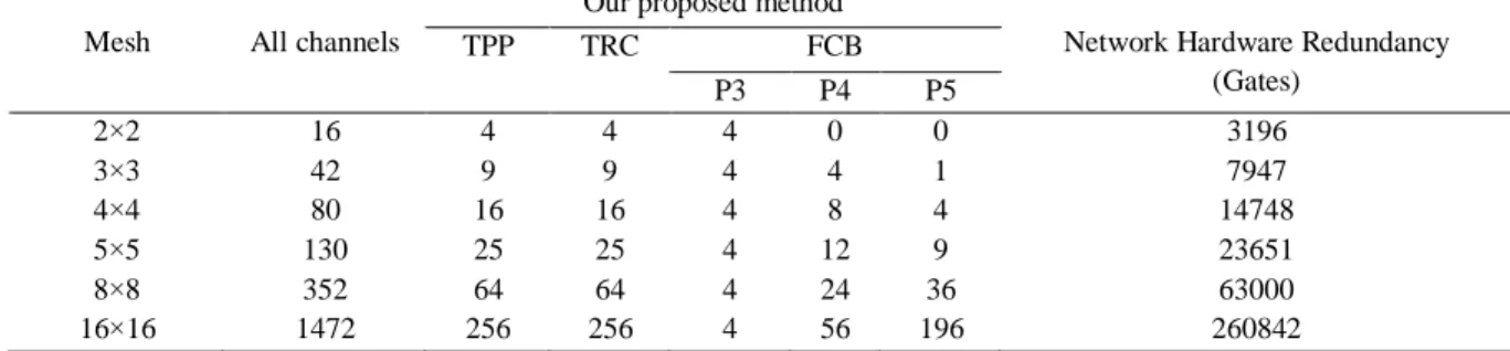
TPP in [36], we consider TRC has 341 gates and TPP has 401 gates. Generally, Table 6 is demonstrated the hardware overhead in OSDTM for several NoC sizes. Table 6. The NoC hardware redundancy
Mesh All channels
Our proposed method
Network Hardware Redundancy (Gates)
TPP TRC FCB
P3 P4 P5
2×2 16 4 4 4 0 0 3196
3×3 42 9 9 4 4 1 7947
4×4 80 16 16 4 8 4 14748
5×5 130 25 25 4 12 9 23651
8×8 352 64 64 4 24 36 63000
16×16 1472 256 256 4 56 196 260842
VII. TEST TIMING
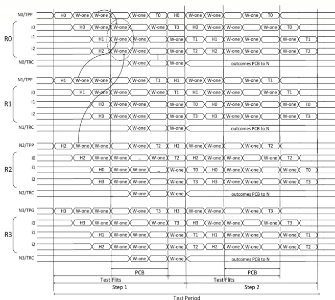
In this paper, we are supposed the tester is a distributed test program that is executed on all IP cores. The test program controls the test process. The test time is identified as the time among the first Flit is generated in TPP and the last Flit compiled in TRC. According
OSDTM, it is necessary the Flits containing W-ONE vectors to pass all links and routers. In each step, consequently, one test packet is generated and released in the network. The packets are generated simultaneously to enhance parallelization and to reduce the test time. Fig.7, in detail, depicts the signals and exchanged data in a 2×2 Mesh NoC.
N0/TRC R0
i0 i1 i2
N0/TPP W-one W-one
H0 W-one W-one
W-one W-one W-one W-one W-one W-one W-one T0 W-one W-one W-one W-one W-one W-one W-one W-one W-one T0 W-one W-one W-one W-one W-one W-one outcomes PCB to N
Step 1 Step 2
Test Period H0 H1 H2 H0 H0 H1 H2 T0 T1 T2 T0 T1 T2 N1/TRC R1 i0 i1 i2
N1/TPP W-one W-one
H1 W-one W-one
W-one W-one W-one W-one W-one W-one W-one T1 W-one W-one W-one W-one W-one W-one W-one W-one W-one T1 W-one W-one W-one W-one W-one W-one outcomes PCB to N
H1 H0 H3 H1 H1 H0 H3 T1 T0 T3 T1 T0 T3 N2/TRC R2 i0 i1 i2
N2/TPP W-one W-one
H2 W-one W-one
W-one W-one ... W-one W-one W-one W-one W-one T2 ... W-one W-one W-one W-one W-one W-one W-one W-one W-one T2 W-one W-one W-one W-one W-one W-one outcomes PCB to N
H2 H0 H3 H2 H2 H0 H3 T2 T0 T3 T2 T0 T3 N3/TRC R3 i0 i1 i2
N3/TPG W-one W-one
H3 W-one W-one
W-one W-one W-one W-one W-one W-one W-one T3 W-one W-one W-one W-one W-one W-one W-one W-one W-one T3 W-one W-one W-one W-one W-one W-one outcomes PCB to N
H3 H1 H2 H3 H3 H1 H2 T3 T1 T2 T3 T1 T2
Test Flits Test Flits
PCB PCB
Fig.7. OSDTM timing Simultaneously, the TPPs in NoC are producing the test
vectors and the TRCs compiles the results. Let’s see the TRC signal, in step 1, is receiving faultless W-one Flit and discovering the defect on (Ri, Ni) link, and in step 2, the FCB is employing idle time to send the result (fault data) to Network Adapter.
VIII. SIMULATION RESULTS AND COMPARISONS But about the simulation, we are employed the NOXIM (cycle accurate simulator) to implement OSDTM on a Mesh NoC with regarding to Table 7 configuration. The size of Mesh network is considered 5*5 for obtaining more stable results.
Table 7. Pre-setting of simulation
Warm-up Simulation time Drained packets Injection rate link width Packet length(Flit) Flit length(bit) NoC 1000 10000 248 0.01 10 12 32 5*5
By running simulation, the faults are injected to the NoC up to discovering threshold and even over it. We register the statistics of NoC and so we realized the OSDTM impacts on the NoC parameters which is depicted in in Fig.8.
0 200 400 600 800 1000 1200
0 6 1 2 2 2 3 7 5 2 6 4 7 6 8 8 1 0 01 0 5 NO. FAULTY CHANNELS
A V R . D E L A Y ( M I L I S E C O N D )
proposed random traffic
Fig.8. the OSDTM impacts on performance (power consumption and delay)
The sudden climb in the both diagram demonstrates the discovering threshold in the OSDTM. The diagram has reached to final level i.e 75. It is means the OSDTM can discovers 75 faulty links in the one test period. Additional to 75, 25 links is verified in TRC, so, totally 100 faulty links can be discovered through OSDTM in a 5*5 Mesh NoC. The OSDTM has planned to discover the injected faults and specify their positions. The delay and power consumption have increased in discovering threshold point and the decreased, because the FCB has been programed to be enabled but for up to threshold, the FCB is inactive. In the Figure 8, there is another diagram only for comparing the performance of NoC in random traffic and tNV traffic.
IX. CONCLUSION
In the current paper, an Offline-Structural Distributed Test Mechanism (OSDTM) is presented to discover and emplace short defects in the data links. It is vital, for implementation of OSDTM to establish specific traffic namely to-Neighbors Vector (tNV). In tNV, test packets including head, tail and W-one vectors are passed all the NoC links. The TPP and TRC are located in Network Adapter and TPP produces and sends test Flits to neighbor routers. The OSDTM depend on this fact that the Flits log in the router from various doorways, if are equal it is means there is no fault and if are not equal then in links Flits passed is defects. The simulation statistic are achieved NOXIM demonstrate the OSDTM is 100% test coverage and 82.3% fault discovering and 100% fault emplacement in large scale NoCs. The FCB hardware specification in compare with Vici router hardware is negligible. As a future work, this is will be worth to study on online testing and reusing router resources to design FCB.
X. REFERENCES
[1] S. Borkar, "Thousand core chips: a technology perspective," in Proceedings of the 44th annual Design
Automation Conference, 2007, pp. 746-749.
[2] C. A. Zeferino, M. E. Kreutz, L. Carro, and A. A. Susin, "A study on communication issues for systems-on-chip,"
in Integrated Circuits and Systems Design, 2002.
Proceedings. 15th Symposium on, 2002, pp. 121-126.
[3] B. Vermeulen, J. Dielissen, K. Goossens, and C. Ciordas, "Bringing communication networks on a chip: test and verification implications," Communications Magazine,
IEEE, vol. 41, pp. 74-81, 2003.
[4] L. Benini and G. De Micheli, "Networks on chips: a new SoC paradigm," Computer, vol. 35, pp. 70-78, 2002.
[5] A. Agarwal, C. Iskander, and R. Shankar, "Survey of network on chip (noc) architectures & contributions,"
Journal of engineering, Computing and Architecture,
vol. 3, pp. 21-27, 2009.
[6] W. J. Dally and B. P. Towles, Principles and practices of
interconnection networks: Elsevier, 2004.
[7] J. Henkel, W. Wolf, and S. Chakradhar, "On-chip networks: A scalable, communication-centric embedded system design paradigm," in VLSI Design, 2004.
Proceedings. 17th International Conference on, 2004,
pp. 845-851.
[8] R. S. Ramanujam, V. Soteriou, B. Lin, and L.-S. Peh, "Design of a high-throughput distributed shared-buffer NoC router," in Networks-on-Chip (NOCS), 2010 Fourth
ACM/IEEE International Symposium on, 2010, pp.
69-78.
[9] C.-H. Chan, K.-L. Tsai, F. Lai, and S.-H. Tsai, "A priority based output arbiter for NoC router," in Circuits and Systems (ISCAS), 2011 IEEE International Symposium on, 2011, pp. 1928-1931.
[10] S. Saponara, F. Vitullo, E. Petri, L. Fanucci, M. Coppola, and R. Locatelli, "Coverage-driven verification of HDL IP cores," in Solutions on Embedded Systems, ed: Springer, 2011, pp. 105-119.
[11] L. Wilson, "International technology roadmap for semiconductors (ITRS)," Semiconductor Industry Association, 2013.
[12] A. C. Cheng, "Comprehensive Study on designing Memory BIST: Algorithms, implementations and TRCde-offs," Ann Arbor, vol. 1001, pp. 48109-2122, 2002.
[13] C. Grecu, P. Pande, A. Ivanov, and R. Saleh, "BIST for network-on-chip interconnect infrastructures," in VLSI
Test Symposium, 2006. Proceedings. 24th IEEE, 2006,
pp. 6 pp.-35.
[14] E. F. Cota, F. G. d. L. Kastensmidt, M. C. d. Santos, M. B. Hervé, P. R. V. d. Almeida, P. R. M. Meirelles, et al., "A high-fault-coverage approach for the test of data, control, and handshake interconnects in mesh networks-on-chip," IEEE TRCnsactions on computers. New York.
Vol. 57, no 9 (Sept. 2008), p. 1202-1215, 2008.
[15] É. Cota, L. Carro, and M. Lubaszewski, "Reusing an on-chip network for the test of core-based systems," ACM TRCnsactions on Design Automation of Electronic
Systems (TODAES), vol. 9, pp. 471-499, 2004.
[16] J.-S. Kim, M.-S. Hwang, S. Roh, J.-Y. Lee, K. Lee, S.-J. Lee, et al., "On-chip network based embedded core testing," in SOC Conference, 2004. Proceedings. IEEE
International, 2004, pp. 223-226.
[17] B. Aghaei and S. Babaei, "The new test wrapper design for core testing in Packet-Switched Micro-Network on Chip," in Proceedings of the 2nd International Conference on Power Electronics and Intelligent
TRCnsportation System (PEITS), 2009, pp. 19-20.
[18] Z. Ying, W. Ning, G. Fen, C. Xin, and Z. Lei, "Novel Core Test Wrapper Design Supporting Multi-mode Testing of NoC-based SoC," International Journal of Control & Automation, vol. 6, 2013.
[19] T. Han, I. Choi, H. Oh, and S. Kang, "A Scalable and Parallel Test Access STRCtegy for NoC-Based Multicore System," in Test Symposium (ATS), 2014 IEEE
23rd Asian, 2014, pp. 81-86.
[20] A. M. Amory, K. Goossens, E. J. Marinissen, M. Lubaszewski, and F. Moraes, "Wrapper design for the reuse of a bus, network-on-chip, or other functional interconnect as test access mechanism," Computers &
Digital Techniques, IET, vol. 1, pp. 197-206, 2007.
[21] A. M. Amory, E. Brião, É. Cota, M. Lubaszewski, and F. G. Moraes, "A scalable test sTRCtegy for network-on-chip routers," in Test Conference, 2005. Proceedings.
ITC 2005. IEEE International, 2005, pp. 9 pp.-599.
[22] G. Nazarian, "On-line testing of routers in networks-on-chip," TU Delft, Delft University of Technology, 2008. [23] S. Babaei, M. Mansouri, B. Aghaei, and A.
Khadem-Zadeh, "Online-Structural Testing of Routers in Network on Chip," World Applied Sciences Journal, vol. 14, pp. 1374-1383, 2011.
[24] É. Cota, A. de Morais Amory, and M. S. Lubaszewski, "Test and Diagnosis of Routers," in Reliability, 0
2 4 6 8 10 12
0 6 1 2 2 2 3 7 5 2 6 4 7 6 8 8 1 0 0 1 0 5 NO. FAULTY TRCFFIC
P O W E R C O N S U M T I O N ( M I C R O J O U L E )
proposed random traffic
Availability and Serviceability of Networks-on-Chip, ed: Springer, 2012, pp. 115-132.
[25] M. Nazari, M. Zolfy Lighvan, Z. Daie Koozekonani, and A. Sadeghi, "A Novel HW/SW Based NoC Router Self-Testing Methodology," arXiv preprint
arXiv:1609.04569, 2016.
[26] S. S. Alamian, R. Fallahzadeh, S. Hessabi, and J. Alirezaie, "A novel test sTRCtegy and fault-tolerant routing algorithm for NoC routers," in The 17th CSI International Symposium on Computer Architecture &
Digital Systems (CADS 2013), 2013, pp. 133-136.
[27] M. Hosseinabady, A. Dalirsani, and Z. Navabi, "Using the inter-and inTRC-switch regularity in NoC switch testing," in Proceedings of the conference on Design,
automation and test in Europe, 2007, pp. 361-366.
[28] A. Alaghi, N. Karimi, M. Sedghi, and Z. Navabi, "Online NoC switch fault discovering and diagnosis using a high level fault model," in 22nd IEEE International Symposium on Defect and Fault-Tolerance in VLSI
Systems (DFT 2007), 2007, pp. 21-29.
[29] W. H. Kautz, "Testing for faults in wiring networks,"
IEEE TRCnsactions on Computers, vol. 100, pp.
358-363, 1974.
[30] A. Hassan, J. Rajski, and V. K. Agarwal, "Testing and diagnosis of interconnects using boundary scan architecture," in Test Conference, 1988. Proceedings.
New Frontiers in Testing, International, 1988, pp.
126-137.
[31] J.-C. Lien and M. A. Breuer, "Maximal Diagnosis for Wiring Networks," in ITC, 1991, pp. 96-105.
[32] A. Krstic and K.-T. Cheng, Delay fault testing for VLSI circuits vol. 14: Springer Science & Business Media, 1998.
[33] M. Cuviello, S. Dey, X. Bai, and Y. Zhao, "Fault modeling and simulation for crosstalk in system-on-chip interconnects," in Proceedings of the 1999 IEEE/ACM
international conference on Computer-aided design,
1999, pp. 297-303.
[34] R. Ubar and J. Raik, "Testing sTRCtegies for networks on chip," in Networks on chip, ed: Springer, 2003, pp. 131-152.
[35] K. Petersén and J. Öberg, "Toward a scalable test methodology for 2D-mesh network-on-chips," in
Proceedings of the conference on Design, automation
and test in Europe, 2007, pp. 367-372.
[36] M. Herve, E. Cota, F. L. Kastensmidt, and M. Lubaszewski, "Diagnosis of interconnect shorts in mesh NoCs," in Proceedings of the 2009 3rd ACM/IEEE
International Symposium on Networks-on-Chip, 2009,
pp. 256-265.
[37] C. Concatto, P. Almeida, F. Kastensmidt, E. Cota, M. Lubaszewski, and M. Herve, "Improving yield of torus NoCs through fault-diagnosis-and-repair of interconnect faults," in 2009 15th IEEE International On-Line Testing
Symposium, 2009, pp. 61-66.
[38] M. Hervé, P. Almeida, F. L. Kastensmidt, E. Cota, and M. Lubaszewski, "Concurrent test of network-on-chip interconnects and routers," in 2010 11th Latin American
Test Workshop, 2010.
[39] A. STRCno, C. Gómez, D. Ludovici, M. Favalli, M. E. Gómez, and D. Bertozzi, "Exploiting network-on-chip structural redundancy for a cooperative and scalable built-in self-test architecture," in 2011 Design, Automation & Test in Europe, 2011, pp. 1-6.
[40] M. R. Kakoee, V. Bertacco, and L. Benini, "A distributed and topology-agnostic approach for on-line NoC testing,"
in Proceedings of the Fifth ACM/IEEE International
Symposium on Networks-on-Chip, 2011, pp. 113-120.
[41] A. Ghofrani, R. Parikh, S. Shamshiri, A. DeOrio, K.-T. Cheng, and V. Bertacco, "Comprehensive online defect diagnosis in on-chip networks," in VTS, 2012, pp. 44-49. [42] M. R. Kakoee, V. Bertacco, and L. Benini, "At-Speed Distributed Functional Testing to Detect Logic and Delay Faults in NoCs," Computers, IEEE TRCnsactions on, vol. 63, pp. 703-717, 2014.
[43] B. Bhowmik, J. K. Deka, and S. Biswas, "An odd-even model for diagnosis of shorts on NoC interconnects," in
2015 Annual IEEE India Conference (INDICON), 2015,
pp. 1-6.
[44] B. Bhowmik, S. Biswas, and J. K. Deka, "Impact of NoC interconnect shorts on performance metrics," in
Communication (NCC), 2016 Twenty Second National
Conference on, 2016, pp. 1-6.
[45] B. Bhowmik, J. K. Deka, and S. Biswas, "An on-line test solution for addressing interconnect shorts in on-chip networks," in On-Line Testing and Robust System Design
(IOLTS), 2016 IEEE 22nd International Symposium on,
2016, pp. 9-12.
[46] R. Holsmark and S. Kumar, "Design issues and performance evaluation of mesh NoC with regions," in
2005 NORCHIP, 2005, pp. 40-43.
[47] G. Chen, "SPAcENoCs: A Scalable Platform for FPGA Accelerated Emulator of NoCs," Texas A&M University, 2013.
[48] C. E. Stroud, A Designer's Guide to Built-in Self-test vol. 19: Springer Science & Business Media, 2002. [49] I. Xilinx, "Design Suite version 14.4," ed, 2014. [50] X. D. Spartan, "3E FPGA Family Data Sheet," DS312
July, vol. 19, 2013.
[51] D. Fick, A. DeOrio, J. Hu, V. Bertacco, D. Blaauw, and D. Sylvester, "Vicis: a reliable network for unreliable silicon," in Proceedings of the 46th Annual Design
Automation Conference, 2009, pp. 812-817.
Babak Aghaei received the B.Sc. degree in Computer Engineering (Hardware) in Shomal University, Amol, Iran and the M.Sc. degree in Computer Achitectures in Islamic Azad University, Tabriz Branch, Iran, and the Ph.D. degree in Computer Engineering (Hardware) from Islamic Azad University, Science and Research Branch (SRBIAU), Tehran, Iran in 2007, 2009, and 2017, respectively. His study fields are SoC, Netorks on Chip (NoC), Design for Test (DfT), Fault Tolerance and Reliability.
Ahmad Khademzadeh was born in Mashhad, Iran, in 1943. He received the B.Sc. degree in applied physics from Ferdowsi University, Mashhad, Iran, in 1969 and the M.Sc., Ph.D. degrees respectively in Digital
Communication and
Information Theory and Error Control Coding from the University of Kent, Canterbury, U.K. He is currently the Head of Education and National Scientific and Informational Scientific Cooperation Department at Iran Telecom Research Center (ITRC).He was the head of Test Engineering Group and the director of Computer and Communication Department at ITRC. He is also a lecturer at Tehran Universities and he is a committee member of Iranian Computer society and also a committee member of the Iranian Electrical Engineering Conference Permanent Committee. Dr. Khadem Zadeh has been received four distinguished national and international awards including Kharazmi International Award, and has been selected as the National outstanding researcher of the Iran Ministry of Information and Communication Technology.
Midia Reshadi Received his M.Sc. degree in computer architecture from Science and Research Branch of Islamic Azad University (SRBIAU), Tehran, Iran in 2005. He also received his Ph.D. degree in computer architecture from SRBIAU, Tehran, Iran in 2010. He is currently Assistant Professor in Faculty of Electrical and Computer Engineering of SRBIAU. His research interests include Photonic NoCs, fault and yield issues in NoCs, routing and switching in on-chip communication networks. He is a member of IEEE.
Kambiz Badie is currently Knowledge Management and e-Organizations Group, IT Research Faculty, Research Institute for ICT, Tehran, Iran. He received all his degrees from Tokyo Institute of Technology, Japan, majoring in pattern recognition. His interest for pattern recognition lies mostly in his motivation for grasping the mechanisms behind cognitive processes such as perception, intuition, imagination and interpretation. Dr. Badie is one of the active researchers in the areas of interdisciplinary and interdisciplinary studies in Iran, and has a high motivation for applying intelligent/ cognitive modeling methodology to the human issues.
Saeid Sarhangi received the B.Sc. degree in Computer Engineering-Software Islamic Azad University, Malekan Branch, Iran in 2015 and the M.Sc. degree in computer-Software in Islamic Azad University, Miandoab Branch, Iran in 2018. His field studies are reliability and fault tolerance in Network on Chip.