Lest We Remember: Cold Boot Attacks on Encryption Keys
J. Alex Halderman
∗, Seth D. Schoen
†, Nadia Heninger
∗, William Clarkson
∗, William Paul
‡,
Joseph A. Calandrino
∗, Ariel J. Feldman
∗, Jacob Appelbaum, and Edward W. Felten
∗ ∗Princeton University
†Electronic Frontier Foundation
‡Wind River Systems
{jhalderm, nadiah, wclarkso, jcalandr, ajfeldma, felten}@cs.princeton.edu [email protected], [email protected], [email protected]
Abstract
Contrary to popular assumption, DRAMs used in most modern computers retain their contents for several sec-onds after power is lost, even at room temperature and even if removed from a motherboard. Although DRAMs become less reliable when they are not refreshed, they are not immediately erased, and their contents persist
sufficiently for malicious (or forensic) acquisition of
us-able full-system memory images. We show that this phe-nomenon limits the ability of an operating system to pro-tect cryptographic key material from an attacker with physical access. We use cold reboots to mount successful attacks on popular disk encryption systems using no
spe-cial devices or materials. We experimentally characterize
the extent and predictability of memory remanence and report that remanence times can be increased dramatically with simple cooling techniques. We offer new algorithms for finding cryptographic keys in memory images and for correcting errors caused by bit decay. Though we discuss
several strategies for partially mitigating these risks, we
know of no simple remedy that would eliminate them.
1 Introduction
Most security experts assume that a computer’s memory
is erased almost immediately when it loses power, or that whatever data remains is difficult to retrieve without
spe-cialized equipment. We show that these assumptions are
incorrect. Ordinary DRAMs typically lose their contents gradually over a period of seconds, even at standard oper-ating temperatures and even if the chips are removed from the motherboard, and data will persist for minutes or even hours if the chips are kept at low temperatures. Residual data can be recovered using simple, nondestructive tech-niques that require only momentary physical access to the machine.
We present a suite of attacks that exploit DRAM re-manence effects to recover cryptographic keys held in
memory. They pose a particular threat to laptop users who rely on disk encryption products, since an adversary who
steals a laptop while an encrypted disk is mounted could employ our attacks to access the contents, even if the com-puter is screen-locked or suspended. We demonstrate this risk by defeating several popular disk encryption systems, including BitLocker, TrueCrypt, and FileVault, and we expect many similar products are also vulnerable.
While our principal focus is disk encryption, any
sen-sitive data present in memory when an attacker gains physical access to the system could be subject to attack. Many other security systems are probably vulnerable. For example, we found that Mac OS X leaves the user’s
lo-gin password in memory, where we were able to recover
it, and we have constructed attacks for extracting RSA private keys from Apache web servers.
As we discuss in Section 2, certain segments of the computer security and semiconductor physics communi-ties have been conscious of DRAM remanence effects for some time, though strikingly little about them has been published. As a result, many who design, deploy, or rely on secure systems are unaware of these phenomena or the ease with which they can be exploited. To our knowledge, ours is the first comprehensive study of their security consequences.
Highlights and roadmap In Section 3, we describe experiments that we conducted to characterize DRAM remanence in a variety of memory technologies. Contrary to the expectation that DRAM loses its state quickly if
it is not regularly refreshed, we found that most DRAM modules retained much of their state without refresh, and
even without power, for periods lasting thousands of re-fresh intervals. At normal operating temperatures, we generally saw a low rate of bit corruption for several sec-onds, followed by a period of rapid decay. Newer memory technologies, which use higher circuit densities, tended to decay more quickly than older ones. In most cases, we
and to predictable “ground states” rather than to random
values.
We also confirmed that decay rates vary dramatically with temperature. We obtained surface temperatures of approximately−50◦Cwith a simple cooling technique:
discharging inverted cans of “canned air” duster spray directly onto the chips. At these temperatures, we
typi-cally found that fewer than 1% of bits decayed even after
10 minutes without power. To test the limits of this ef-fect, we submerged DRAM modules in liquid nitrogen
(ca.−196◦C) and saw decay of only 0.17% after 60
min-utes out of the computer.
In Section 4, we present several attacks that exploit DRAM remanence to acquire memory images from which keys and other sensitive data can be extracted. Our attacks come in three variants, of increasing resistance to coun-termeasures. The simplest is to reboot the machine and launch a custom kernel with a small memory footprint that gives the adversary access to the retained memory. A more advanced attack briefly cuts power to the machine, then restores power and boots a custom kernel; this de-prives the operating system of any opportunity to scrub memory before shutting down. An even stronger attack cuts the power and then transplants the DRAM modules to a second PC prepared by the attacker, which extracts their state. This attack additionally deprives the original BIOS and PC hardware of any chance to clear the memory on boot. We have implemented imaging kernels for use with network booting or a USB drive.
If the attacker is forced to cut power to the memory for too long, the data will become corrupted. We propose three methods for reducing corruption and for correct-ing errors in recovered encryption keys. The first is to
cool the memory chips prior to cutting power, which
dra-matically reduces the error rate. The second is to apply algorithms we have developed for correcting errors in private and symmetric keys. The third is to replicate the physical conditions under which the data was recovered
and experimentally measure the decay properties of each memory location; with this information, the attacker can conduct an accelerated error correction procedure. These
techniques can be used alone or in combination.
In Section 5, we explore the second error correction method: novel algorithms that can reconstruct crypto-graphic keys even with relatively high bit-error rates.
Rather than attacking the key directly, our methods
con-sider values derived from it, such as key schedules, that provide a higher degree of redundancy. For performance
reasons, many applications precompute these values and
keep them in memory for as long as the key itself is in use. To reconstruct an AES key, for example, we treat the decayed key schedule as an error correcting code and find the most likely values for the original key. Applying this method to keys with 10% of bits decayed, we can
recon-struct nearly any 128-bit AES key within a few seconds. We have devised reconstruction techniques for AES, DES, and RSA keys, and we expect that similar approaches
will be possible for other cryptosystems. The
vulnerabil-ity of precomputation products to such attacks suggests an interesting trade-off between efficiency and security. In Section 6, we present fully automatic techniques for
identifying such keys from memory images, even in the
presence of bit errors.
We demonstrate the effectiveness of these attacks in Section 7 by attacking several widely used disk encryption products, including BitLocker, TrueCrypt, and FileVault.
We have developed a fully automated demonstration
at-tack against BitLocker that allows access to the contents of the disk with only a few minutes of computation. No-tably, using BitLocker with a Trusted Platform Module (TPM) sometimes makes itlesssecure, allowing an at-tacker to gain access to the data even if the machine is stolen while it is completely powered off.
It may be difficult to prevent all the attacks that we de-scribe even with significant changes to the way encryption products are designed and used, but in practice there are a number of safeguards that can provide partial resistance. In Section 8, we suggest a variety of mitigation strategies ranging from methods that average users can apply to-day to long-term software and hardware changes. Each remedy has limitations and trade-offs. As we conclude in Section 9, it seems there is no simple fix for DRAM remanence vulnerabilities.
Online resources A video demonstration of our attacks and source code for some of our tools are available at http://citp.princeton.edu/memory.
2 Previous Work
Previous researchers have suggested that data in DRAM might survive reboots, and that this fact might have
se-curity implications. To our knowledge, however, ours is
the first security study to focus on this phenomenon, the first to consider how to reconstruct symmetric keys in the presence of errors, the first to apply such attacks to real disk encryption systems, and the first to offer a systematic discussion of countermeasures.
We owe the suggestion that modern DRAM contents can survive cold boot to Pettersson [33], who seems to have obtained it from Chow, Pfaff, Garfinkel, and Rosen-blum [13]. Pettersson suggested that remanence across
cold boot could be used to acquire forensic memory
im-ages and obtain cryptographic keys, although he did not experiment with the possibility. Chowet al.discovered this property in the course of an experiment on data life-time in running systems. While they did not exploit the
Memory Type Chip Maker Memory Density Make/Model Year
A SDRAM Infineon 128Mb Dell Dimension 4100 1999
B DDR Samsung 512Mb Toshiba Port´eg´e 2001
C DDR Micron 256Mb Dell Inspiron 5100 2003
D DDR2 Infineon 512Mb IBM T43p 2006
E DDR2 Elpida 512Mb IBM x60 2007
F DDR2 Samsung 512Mb Lenovo 3000 N100 2007
Table 1: Test systems we used in our experiments property, they remark on the negative security
implica-tions of relying on a reboot to clear memory.
In a recent presentation, MacIver [31] stated that Mi-crosoft considered memory remanence attacks in design-ing its BitLocker disk encryption system. He acknowl-edged that BitLocker is vulnerable to having keys ex-tracted by cold-booting a machine when it is used in “basic mode” (where the encrypted disk is mounted
auto-matically without requiring a user to enter any secrets), but he asserted that BitLocker is not vulnerable in “ad-vanced modes” (where a user must provide key material to access the volume). He also discussed cooling mem-ory with dry ice to extend the retention time. MacIver apparently has not published on this subject.
It has been known since the 1970s that DRAM cell contents survive to some extent even at room temperature and that retention times can be increased by cooling. In a 1978 experiment [29], a DRAM showed no data loss for a full week without refresh when cooled with liquid nitrogen. Anderson [2] briefly discusses remanence in his 2001 book:
[A]n attacker can . . . exploit . . . memory
re-manence, the fact that many kinds of computer memory retain some trace of data that have been stored there. . . . [M]odern RAM chips exhibit a wide variety of memory remanence behaviors, with the worst of them keeping data for several
seconds even at room temperature. . .
Anderson cites Skorobogatov [40], who found signifi-cant data retention times withstaticRAMs at room tem-perature. Our results for modern DRAMs show even longer retention in some cases.
Anderson’s main focus is on “burn-in” effects that oc-cur when data is stored in RAM for an extended period.
Gutmann [22,23] also examines “burn-in,” which he at-tributes to physical changes that occur in semiconductor memories when the same value is stored in a cell for a long time. Accordingly, Gutmann suggests that keys should not be stored in one memory location for longer than several minutes. Our findings concern a different phenomenon: the remanence effects we have studied oc-cur in modern DRAMs even when data is stored only
momentarily. These effects do not result from the kind of physical changes that Gutmann described, but rather from the capacitance of DRAM cells.
Other methods for obtaining memory images from live systems include using privileged software running un-der the host operating system [43], or using DMA trans-fer on an external bus [19], such as PCI [12], mini-PCI, Firewire [8,15,16], or PC Card. Unlike these techniques, our attacks do not require access to a privileged account on the target system, they do not require specialized hard-ware, and they are resistant to operating system counter-measures.
3 Characterizing Remanence Effects
A DRAM cell is essentially a capacitor. Each cell encodes a single bit by either charging or not charging one of the capacitor’s conductors. The other conductor is hard-wired either to power or to ground, depending on the cell’s address within the chip [37, 23].Over time, charge will leak out of the capacitor, and the cell will lose its state or, more precisely, it will decay to its ground state, either zero or one depending on whether the fixed conductor of the capacitor is hard-wired to ground or power. To forestall this decay, the cell must berefreshed, meaning that the capacitor must be re-charged to hold its value. Specifications for DRAM chips give arefresh
time, which is the maximum interval that is supposed to
pass before a cell is refreshed. The standard refresh time (usually on the order of milliseconds) is meant to achieve extremely high reliability for normal computer operations where even infrequent bit errors could cause serious prob-lems; however, a failure to refresh any individual DRAM cell within this time has only a tiny probability of actually destroying the cell’s contents.
We conducted a series of experiments to characterize DRAM remanence effects and better understand the secu-rity properties of modern memories. We performed trials using PC systems with different memory technologies, as shown in Table 1. These systems included models from several manufacturers and ranged in age from 9 years to 6 months.
3.1 Decay at operating temperature
Using a modified version of our PXE memory imaging
program (see Section 4.1), we filled representative
mem-ory regions with a pseudorandom pattern. We read back these memory regions after varying periods of time with-out refresh and under different temperature conditions, and measured the error rate of each sample. The error
rate is the number of bit errors in each sample (the Ham-ming distance from the pattern we had written) divided by the total number of bits we measured. Since our pseudo-random test pattern contained roughly equal numbers of zeros and ones, we would expect fully decayed memory to have an error rate of approximately 50% .
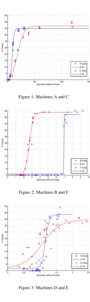
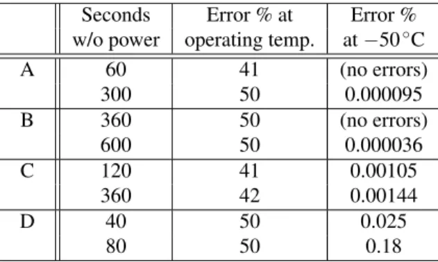
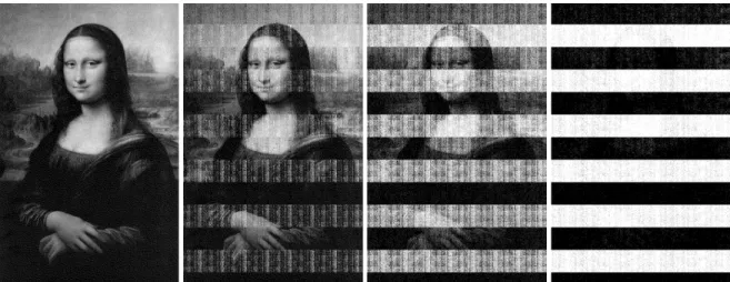
Our first tests measured the decay rate of each mem-ory module under normal operating temperature, which ranged from 25.5◦C to44.1◦C, depending on the ma-chine (see Figures 1, 2, and 3). We found that the dimen-sions of the decay curves varied considerably between
machines, with the fastest exhibiting complete data loss
in approximately 2.5 seconds and the slowest taking an average of 35 seconds. However, the decay curves all dis-play a similar shape, with an initial period of slow decay, followed by an intermediate period of rapid decay, and then a final period of slow decay.
We calculated best fit curves to the data using the logis-tic function because MOSFETs, the basic components of
a DRAM cell, exhibit a logistic decay curve. We found
that machines using newer memory technologies tend to
exhibit a shorter time to total decay than machines using older memory technologies, but even the shorter times are long enough to facilitate most of our attacks. We as-cribe this trend to the increasing density of the DRAM cells as the technology improves; in general, memory with higher densities have a shorter window where data is recoverable. While this trend might make DRAM
re-tention attacks more difficult in the future, manufacturers
also generally seek toincreaseretention times, because DRAMs with long retention require less frequent refresh and have lower power consumption.
3.2 Decay at reduced temperature
It has long been known that low temperatures can
signifi-cantly increase memory devices’ retention times [29,2, 46,23,41,40]. To measure this effect, we performed a second series of tests using machines A–D.
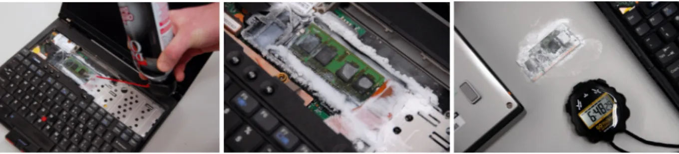
In each trial, we loaded a pseudorandom test pattern into memory, and, with the computer running, cooled the memory module to approximately−50◦C. We then powered off the machine and maintained this temperature until power was restored. We achieved these temperatures using commonly available “canned air” duster products (see Section 4.2), which we discharged, with the can inverted, directly onto the chips.
0 50 100 150
0 5 10 15 20 25 30 35 40 45 50
Seconds without Power
% Decay
A Data A Fit C Data C Fit
Figure 1: Machines A and C
0 1 2 3 4 5 6 7 8 9 10
0 5 10 15 20 25 30 35 40 45 50
Seconds without Power
% Decay
B Data B Fit F Data F Fit
Figure 2: Machines B and F
0 0.5 1 1.5 2 2.5
0 5 10 15 20 25 30 35 40 45 50
Seconds without Power
% Decay
D Data D Fit E Data E Fit
Seconds Error % at Error % w/o power operating temp. at−50◦C
A 60 41 (no errors)
300 50 0.000095
B 360 50 (no errors)
600 50 0.000036
C 120 41 0.00105
360 42 0.00144
D 40 50 0.025
80 50 0.18
Table 2: Effect of cooling on error rates As expected, we observed a significantly lower rate
of decay under these reduced temperatures (see Table 2).
On all of our sample DRAMs, the decay rates were low enough that an attacker who cut power for 60 seconds would recover 99.9% of bits correctly.
As an extreme test of memory cooling, we performed
another experiment using liquid nitrogen as an additional
cooling agent. We first cooled the memory module of Machine A to−50◦Cusing the “canned air” product. We then cut power to the machine, and quickly removed
the DRAM module and placed it in a canister of liquid nitrogen. We kept the memory module submerged in the liquid nitrogen for 60 minutes, then returned it to the machine. We measured only 14,000 bit errors within a 1 MB test region (0.17% decay). This suggests that, even in modern memory modules, data may be recoverable for hours or days with sufficient cooling.
3.3 Decay patterns and predictability
We observed that the DRAMs we studied tended to decay in highly nonuniform patterns. While these patterns
var-ied from chip to chip, they were very predictable in most
of the systems we tested. Figure 4 shows the decay in one memory region from Machine A after progressively longer intervals without power.
There seem to be several components to the decay patterns. The most prominent is a gradual decay to the “ground state” as charge leaks out of the memory cells. In the DRAM shown in Figure 4, blocks of cells alternate between a ground state of 0 and a ground state of 1, result-ing in the series of horizontal bars. Other DRAM models and other regions within this DRAM exhibited different
ground states, depending on how the cells are wired. We observed a small number of cells that deviated from the “ground state” pattern, possibly due to manufacturing variation. In experiments with 20 or 40 runs, a few “ret-rograde” cells (typically∼0.05%of memory cells, but larger in a few devices) always decayed to the opposite value of the one predicted by the surrounding ground state
pattern. An even smaller number of cells decayed in dif-ferent directions across runs, with varying probabilities.
Apart from their eventual states, theorderin which different cells decayed also appeared to be highly pre-dictable. At a fixed temperature, each cell seems to decay after a consistent length of time without power. The rel-ative order in which the cells decayed was largely fixed, even as the decay times were changed by varying the temperature. This may also be a result of manufacturing variations, which result in some cells leaking charge faster than others.
To visualize this effect, we captured degraded memory images, including those shown in Figure 4, after cutting
power for intervals ranging from 1 second to 5 minutes, in 1 second increments. We combined the results into a video (available on our web site). Each test interval began with the original image freshly loaded into memory. We might have expected to see a large amount of variation between frames, but instead, most bits appear stable from frame to frame, switching values only once, after the cell’s decay interval. The video also shows that the decay
intervals themselves follow higher order patterns, likely
related to the physical geometry of the DRAM.
3.4 BIOS footprints and memory wiping
Even if memory contents remain intact while power is off, the system BIOS may overwrite portions of memory when the machine boots. In the systems we tested, the BIOS overwrote only relatively small fractions of memory with its own code and data, typically a few megabytes concentrated around the bottom of the address space.
On many machines, the BIOS can perform a destructive memory check during its Power-On Self Test (POST). Most of the machines we examined allowed this test to be disabled or bypassed (sometimes by enabling an option called “Quick Boot”).
On other machines, mainly high-end desktops and servers that support ECC memory, we found that the
BIOS cleared memory contents without any override
op-tion. ECC memory must be set to a known state to avoid spurious errors if memory is read without being initial-ized [6], and we believe many ECC-capable systems
per-form this wiping operation whether or not ECC memory
is installed.
ECC DRAMs are not immune to retention effects, and
an attacker could transfer them to a non-ECC machine that does not wipe its memory on boot. Indeed, ECC memory could turn out tohelpthe attacker by making DRAM more resistant to bit errors.
Figure 4: We loaded a bitmap image into memory on Machine A, then cut power for varying lengths of time. After 5 seconds (left), the image is indistinguishable from the original. It gradually becomes more degraded, as shown after
30 seconds, 60 seconds, and 5 minutes.
4 Imaging Residual Memory
Imaging residual memory contents requires no special equipment. When the system boots, the memory con-troller begins refreshing the DRAM, reading and rewriting each bit value. At this point, the values are fixed, decay halts, and programs running on the system can read any data present using normal memory-access instructions.
4.1 Imaging tools
One challenge is that booting the system will necessarily overwrite some portions of memory. Loading a full
oper-ating system would be very destructive. Our approach is
to use tiny special-purpose programs that, when booted
from either a warm or cold reset state, produce accurate
dumps of memory contents to some external medium. These programs use only trivial amounts of RAM, and their memory offsets used can be adjusted to some extent to ensure that data structures of interest are unaffected.
Our memory-imaging tools make use of several differ-ent attack vectors to boot a system and extract the contdiffer-ents of its memory. For simplicity, each saves memory images to the medium from which it was booted.
PXE network boot Most modern PCs support net-work booting via Intel’s Preboot Execution Environment
(PXE) [25], which provides rudimentary startup and
net-work services. We implemented a tiny (9 KB) standalone application that can be booted via PXE and whose only function is streaming the contents of system RAM via a UDP-based protocol. Since PXE provides a universal API for accessing the underlying network hardware, the same binary image will work unmodified on any PC sys-tem with PXE support. In a typical attack setup, a laptop
connected to the target machine via an Ethernet crossover cable runs DHCP and TFTP servers as well as a simple client application for receiving the memory data. We have extracted memory images at rates up to 300 Mb/s (around 30 seconds for a 1 GB RAM) with gigabit Ethernet cards. USB drives Alternatively, most PCs can boot from an external USB device such as a USB hard drive or flash device. We implemented a small (10 KB) plug-in for the SYSLINUX bootloader [3] that can be booted from an external USB device or a regular hard disk. It saves the
contents of system RAM into a designated data partition
on this device. We succeeded in dumping 1 GB of RAM to a flash drive in approximately 4 minutes.
EFI boot Some recent computers, including all Intel-based Macintosh computers, implement the Extensible
Firmware Interface (EFI) instead of a PC BIOS. We have
also implemented a memory dumper as an EFI netboot application. We have achieved memory extraction speeds up to 136 Mb/s, and we expect it will be possible to increase this throughput with further optimizations. iPods We have installed memory imaging tools on an Apple iPod so that it can be used to covertly capture memory dumps without impacting its functionality as a music player. This provides a plausible way to conceal the attack in the wild.
4.2 Imaging attacks
An attacker could use imaging tools like ours in a number of ways, depending on his level of access to the system and the countermeasures employed by hardware and soft-ware.
Figure 5: Before powering off the computer, we spray an upside-down canister of multipurpose duster directly onto the
memory chips, cooling them to−50◦C. At this temperature, the data will persist for several minutes after power loss with minimal error, even if we remove the DIMM from the computer.
Simple reboots The simplest attack is to reboot the machine and configure the BIOS to boot the imaging
tool. A warm boot, invoked with the operating system’s restart procedure, will normally ensure that the memory
has no chance to decay, though software will have an opportunity to wipe sensitive data prior to shutdown. A cold boot, initiated using the system’s restart switch or by briefly removing and restoring power, will result in little
or no decay depending on the memory’s retention time. Restarting the system in this way denies the operating system and applications any chance to scrub memory before shutting down.
Transferring DRAM modules Even if an attacker can-not force a target system to boot memory-imaging tools,
or if the target employs countermeasures that erase
mem-ory contents during boot, DIMM modules can be phys-ically removed and their contents imaged using another computer selected by the attacker.
Some memory modules exhibit far faster decay than others, but as we discuss in Section 3.2 above, cooling a module before powering it off can slow decay sufficiently to allow it to be transferred to another machine with mini-mal decay. Widely-available “canned air” dusters, usually containing a compressed fluorohydrocarbon refrigerant, can easily be used for this purpose. When the can is dis-charged in an inverted position, as shown in Figure 5, it dispenses its contents in liquid form instead of as a gas.
The rapid drop in pressure inside the can lowers the
tem-perature of the discharge, and the subsequent evaporation of the refrigerant causes a further chilling. By spraying the contents directly onto memory chips, we can cool their surfaces to−50◦Cand below. If the DRAM is cooled to this temperature before power is cut and kept cold, we can achieve nearly lossless data recovery even after the chip is out of the computer for several minutes.
Removing the memory modules can also allow the attacker to image memory in address regions where stan-dards BIOSes load their own code during boot. The at-tacker could remove the primary memory module from
the target machine and place it into the secondary DIMM slot (in the same machine or another machine), effectively remapping the data to be imaged into a different part of the address space.
5 Key Reconstruction
Our experiments (see Section 3) show that it is possible to recover memory contents with few bit errors even af-ter cutting power to the system for a brief time, but the presence of even a small amount of error complicates the process of extracting correct cryptographic keys. In this section we present algorithms for correcting errors
in symmetric and private keys. These algorithms can
cor-rect most errors quickly even in the presence of relatively high bit error probabilities in the range of 5% to 50%, depending on the type of key.
A na¨ıve approach to key error correction is to brute-force search over keys with a low Hamming distance from the decayed key that was retrieved from memory, but this is computationally burdensome even with a moderate amount of unidirectional error. As an example, if only 10% of the ones have decayed to zeros in our memory image, the data recovered from a 256-bit key with an equal number of ones and zeroes has an expected Hamming distance of 12 from the actual key, and the number of such keys is�12812+12>256.
Our algorithms achieve significantly better perfor-mance by considering data other than the raw form of the key. Most encryption programs speed up computation by storing data precomputed from the encryption keys— for block ciphers, this is most often a key schedule, with subkeys for each round; for RSA, this is an extended form of the private key which includes the primespandqand several other values derived fromd. This data contains much more structure than the key itself, and we can use this structure to efficiently reconstruct the original key even in the presence of errors.
efficiency and security. All of the disk encryption systems we studied (see Section 7) precompute key schedules and
keep them in memory for as long as the encrypted disk is mounted. While this practice saves some computation for each disk block that needs to be encrypted or decrypted, we find that it greatly simplifies key recovery attacks.
Our approach to key reconstruction has the advantage that it is completely self-contained, in that we can recover the key without having to test the decryption of
cipher-text. The data derived from the key, and not the decoded
plaintext, provides a certificate of the likelihood that we have found the correct key.
We have found it useful to adopt terminology from coding theory. We may imagine that the expanded key schedule forms a sort oferror correcting codefor the key, and the problem of reconstructing a key from memory may be recast as the problem of finding the closestcode word(valid key schedule) to the data once it has been passed through a channel that has introduced bit errors. Modeling the decay Our experiments showed that
al-most all memory bits tend to decay to predictable ground
states, with only a tiny fraction flipping in the opposite direction. In describing our algorithms, we assume, for simplicity, that all bits decay to the same ground state.
(They can be implemented without this requirement,
as-suming that the ground state of each bit is known.) If we assume we have no knowledge of the decay pat-terns other than the ground state, we can model the de-cay with thebinary asymmetric channel, in which the probability of a 1 flipping to 0 is some fixedδ0and the
probability of a 0 flipping to a 1 is some fixedδ1.
In practice, the probability of decaying to the ground state approaches 1 as time goes on, while the
probabil-ity of flipping in the opposite direction remains relatively constant and tiny (less than0.1%in our tests). The ground state decay probability can be approximated from recov-ered key data by counting the fraction of 1s and 0s, as-suming that the original key data contained roughly equal proportions of each value.
We also observed that bits tended to decay in a pre-dictable order that could be learned over a series of timed decay trials, although the actual order of decay appeared
fairly random with respect to location. An attacker with
the time and physical access to run such a series of tests could easily adapt any of the approaches in this section to take this order into account and improve the performance of the error-correction. Ideally such tests would be able to replicate the conditions of the memory extraction exactly, but knowledge of the decay order combined with an esti-mate of the fraction of bit flips is enough to give a very
good estimate of an individual decay probability of each
bit. This probability can be used in our reconstruction algorithms to prioritize guesses.
For simplicity and generality, we will analyze the algo-rithms assuming no knowledge of this decay order.
5.1 Reconstructing DES keys
We first apply these methods to develop an error correc-tion technique for DES. The DES key schedule algorithm produces 16 subkeys, each a permutation of a 48-bit sub-set of bits from the original 56-bit key. Every bit from the original key is repeated in about 14 of the 16 subkeys.
In coding theory terms, we can treat the DES key sched-ule as a repetition code: the message is a single bit, and the corresponding codeword is a sequence ofncopies of this bit. Ifδ0=δ1<12, the optimal decoding of such an n-bit codeword is 0 if more thann/2of the recovered bits are 0, and 1 otherwise. Forδ0=δ1, the optimal
decod-ing is 0 if more thannrof the recovered bits are 0 and 1 otherwise, where
r= log(1−δ0)−logδ1
log(1−δ0) +log(1−δ1)−logδ1−logδ0.
Forδ0=.1andδ1=.001(that is, we are in a block
with ground state 0),r=.75and this approach will fail to correctly decode a bit only if more than3of the14copies of a 0 decay to a 1, or more than 11 of the 14 copies of a 1 decay to 0. The probability of this event is less than 10−9. Applying the union bound, the probability that any
of the 56 key bits will be incorrectly decoded is at most 56×10−9<6×10⁻⁸; even at 50% error, the probability
that the key can be correctly decoded without resorting to brute force search is more than 98%.
This technique can be trivially extended to correct er-rors in Triple DES keys. Since Triple DES applies the same key schedule algorithm to two or three 56-bit key components (depending on the version of Triple DES), the probability of correctly decoding each key bit is the same as for regular DES. With a decay rate ofδ0=.5and
probabilityδ1=.001of bit flips in the opposite direction,
we can correctly decode a 112-bit Triple DES key with at least 97% probability and a 168-bit key with at least 96%
probability.
5.2 Reconstructing AES keys
The AES key schedule has a more complex structure than the DES key schedule, but we can still use it to efficiently reconstruct a key in the presence of errors.
A seemingly reasonable approach to this problem would be to search keys in order of distance to the recov-ered key and output any key whose schedule is sufficiently close to the recovered schedule. Our implementation of this algorithm took twenty minutes to search109
round key 1
⊕
⊕
⊕
⊕
Core round key 2
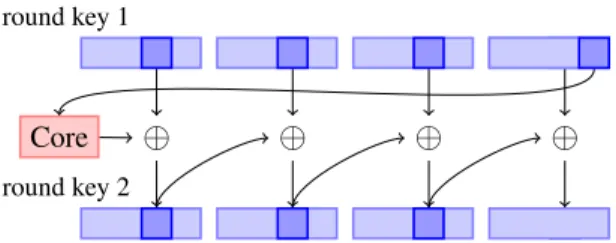
Figure 6: In the 128-bit AES key schedule, three bytes of each round key are entirely determined by four bytes of the preceding round key.
had flipped to ones. At this rate it would take ten days to reconstruct a key with 11 bits flipped.
We can do significantly better by taking advantage of the structure of the AES key schedule. Instead of trying to correct an entire key at once, we can examine a smaller set of bytes at a time. The high amount of linearity in the
key schedule is what permits this separability—we can take advantage of pieces that are small enough to brute
force optimal decodings for, yet large enough that these
decodings are useful to reconstruct the overall key. Once we have a list of possible decodings for these smaller
pieces of the key in order of likelihood, we can combine
them into a full key to check against the key schedule. Since each of the decoding steps is quite fast, the run-ning time of the entire algorithm is ultimately limited by the number of combinations we need to check. The number of combinations is still roughly exponential in the number of errors, but it is a vast improvement over brute force searching and is practical in many realistic cases. Overview of the algorithm For 128-bit keys, an AES key expansion consists of 11 four-word (128-bit) round
keys. The first round key is equal to the key itself. Each
remaining word of the key schedule is generated either by XORing two words of the key schedule together, or by performing the key schedule core (in which the bytes of a word are rotated and each byte is mapped to a new value) on a word of the key schedule and XORing the result with another word of the key schedule.
Consider a “slice” of the first two round keys consisting of byteifrom words 1-3 of the first two round keys, and
bytei−1from word 4 of the first round key (as shown in Figure 6). This slice is 7 bytes long, but is uniquely determined by the four bytes from the key. In theory, there are still232possibilities to examine for each slice,
but we can do quite well by examining them in order of
distance to the recovered key. For each possible set of 4 key bytes, we generate the relevant three bytes of the next round key and calculate the probability, given estimates ofδ0andδ1, that these seven bytes might have decayed
to the corresponding bytes of the recovered round keys. Now we proceed to guess candidate keys, where a
candidate contains a value for each slice of bytes. We
consider the candidates in order of decreasing total
like-lihood as calculated above. For each candidate key we consider, we calculate the expanded key schedule and ask if the likelihood of that expanded key schedule decaying to our recovered key schedule is sufficiently high. If so, then we output the corresponding key as a guess.
When one ofδ0orδ1is very small, this algorithm will
almost certainly output a unique guess for the key. To see this, observe that a single bit flipped in the key results in
a cascade of bit flips through the key schedule, half of which are likely to flip in the “wrong” direction.
Our implementation of this algorithm is able to re-construct keys with 15% error (that is, δ0=.15 and
δ1=.001) in a fraction of a second, and about half of
keys with 30% error within 30 seconds.
This idea can be extended to 256-bit keys by dividing the words of the key into two sections—words 1–3 and 8, and words 4–7, for example—then comparing the words of the third and fourth round keys generated by the bytes of these words and combining the result into candidate round keys to check.
5.3 Reconstructing tweak keys
The same methods can be applied to reconstruct keys for
tweakable encryption modes [30], which are commonly
used in disk encryption systems.
LRW LRW augments a block cipherE(and keyK1) by
computing a “tweak”Xfor each data block and encrypt-ing the block usencrypt-ing the formulaEK1(P⊕X)⊕X. A tweak keyK2is used to compute the tweak,X=K2⊗I, where Iis the logical block identifier. The operations⊕and⊗
are performed in the finite fieldGF(2128).
In order to speed tweak computations, implementations commonly precompute multiplication tables of the values K2xi modP, wherexis the primitive element andPis an
irreducible polynomial overGF(2128)[26]. In practice, Qx modPis computed by shifting the bits ofQleft by one and possibly XORing withP.
Given a value K2xi, we can recover nearly all of the
bits ofK2simply by shifting right byi. The number of
bits lost depends oniand the nonzero elements ofP. An entire multiplication table will contain many copies of
nearly all of the bits ofK2, allowing us to reconstruct the
key in much the same way as the DES key schedule. As an example, we apply this method to reconstruct the LRW key used by the TrueCrypt 4 disk encryption system. TrueCrypt 4 precomputes a 4048-byte multiplication table consisting of 16 blocks of 16 lines of 4 words of 4 bytes each. Line 0 of block 14 contains the tweak key.
The multiplication table is generated line by line from
multiply function to generate four new values, and then XORing all combinations of these four values to create
16 more lines of the table. The shift-and-XOR operation
is performed 64 times to generate the table, using the irreducible polynomialP=x128+x7+x2+x+1. For any
of these 64 values, we can shift rightitimes to recover 128−(8+i)of the bits ofK2, and use these recovered
values to reconstructK2with high probability.
XEX and XTS For XEX [35] and XTS [24] modes, the tweak for block jin sectorIisX=EK2(I)⊗xj, where Iis encrypted with AES andxis the primitive element ofGF(2128). Assuming the key schedule forK2is kept in memory, we can use the AES key reconstruction
tech-niques to reconstruct the tweak key.
5.4 Reconstructing RSA private keys
An RSA public key consists of the modulusN and the public exponente, while the private key consists of the private exponentdand several optional values: prime fac-torspandqofN,d mod(p−1),d mod(q−1), and
q−1 modp. GivenNande, any of the private values is
sufficient to generate the others using the Chinese remain-der theorem and greatest common divisor algorithms. In
practice, RSA implementations store some or all optional values to speed up computation.
There have been a number of results on efficiently re-constructing RSA private keys given a fraction of the bits of private key data. Letn=lgN. Ncan be factored in
polynomial time given then/4least significant bits ofp
(Coppersmith [14]), given then/4least significant bits of d(Boneh, Durfee, and Frankel [9]), or given then/4least
significant bits ofd mod(p−1)(Bl¨omer and May [7]).
These previous results are all based on Coppersmith’s method of finding bounded solutions to polynomial
equa-tions using lattice basis reduction; the number of contigu-ous bits recovered from the most or least significant bits of the private key data determines the additive error tolerated in the solution. In our case, the errors may be distributed across all bits of the key data, so we are searching for
solutions with low Hamming weight, and these previous
approaches do not seem to be directly applicable. Given the public modulus Nand the values p˜andq˜ recovered from memory, we can deduce values for the
originalpandqby iteratively reconstructing them from
the least-significant bits. For unidirectional decay with probabilityδ, bitspiandqiare uniquely determined by
Niand our guesses for thei−1lower-order bits ofpandq (observe thatp0=q0=1), except in the case whenpi˜ and
˜
qiare both in the ground state. This yields a branching process with expected degree (3+δ)8 2. If decay is not unidirectional, we may use the estimated probabilities to weight the branches at each bit.
Combined with a few heuristics—for example, choose the most likely state first, prune nodes by bounds on the
solution, and iteratively increase the bit flips allowed— this results in a practical algorithm for reasonable error rates. This process can likely be improved substantially using additional data recovered from the private key.
We tested an implementation of the algorithm on a fast modern machine. For fifty trials with 1024-bit primes (2048-bit keys) andδ =4%, the median reconstruction time was 4.5 seconds. The median number of nodes
vis-ited was 16,499, the mean was 621,707, and the standard deviation was 2,136,870. Forδ=6%, reconstruction re-quired a median of 2.5 minutes, or 227,763 nodes visited.
For 512-bit primes and δ =10%, reconstruction re-quired a median of 1 minute, or 188,702 nodes visited.
For larger error rates, we can attempt to reconstruct only the firstn/4bits of the key using this process and use the lattice techniques to reconstruct the rest of the key; these computations generally take several hours in practice. For a 1024-bit RSA key, we would need to recover 256 bits of a factor. The expected depth of the tree from our branching reconstruction process would be
(1
2+δ)2256(assuming an even distribution of 0s and 1s)
and the expected fraction of branches that would need to be examined is 1/2+δ2.
6 Identifying Keys in Memory
Extracting encryption keys from memory images requires a mechanism for locating the target keys. A simple ap-proach is to test every sequence of bytes to see whether it
correctly decrypts some known plaintext. Applying this method to a 1 GB memory image known to contain a 128-bit symmetric key aligned to some 4-byte machine word
implies at most 228possible key values. However, this is
only the case if the memory image is perfectly accurate. If there are bit errors in the portion of memory containing the key, the search quickly becomes intractable.
We have developed fully automatic techniques for locat-ing symmetric encryption keys in memory images, even in the presence of bit errors. Our approach is similar to the one we used to correct key bit errors in Section 5. We target the key schedule instead of the key itself, searching for blocks of memory that satisfy (or are close to
satisfy-ing) the combinatorial properties of a valid key schedule. Using these methods we have been able to recover keys
from closed-source encryption programs without having to disassemble them and reconstruct their key data struc-tures, and we have even recovered partial key schedules
that had been overwritten by another program when the memory was reallocated.
Although previous approaches to key recovery do not require a scheduled key to be present in memory, they
for our purposes. Shamir and van Someren [39] pro-pose visual and statistical tests of randomness which can quickly identify regions of memory that might contain key material, but their methods are prone to false posi-tives that complicate testing on decayed memory images. Even perfect copies of memory often contain large blocks of random-looking data that might pass these tests (e.g.,
compressed files). Pettersson [33] suggests a plausibil-ity test for locating a particular program data structure that contains key material based on the range of likely
values for each field. This approach requires the operator
to manually derive search heuristics for each encryption application, and it is not very robust to memory errors.
6.1 Identifying AES keys
In order to identify scheduled AES keys in a memory image, we propose the following algorithm:
1. Iterate through each byte of memory. Treat the fol-lowing block of 176 or 240 bytes of memory as an AES key schedule.
2. For each word in the potential key schedule, calcu-late the Hamming distance from that word to the key schedule word that should have been generated from the surrounding words.
3. If the total number of bits violating the constraints on a correct AES key schedule is sufficiently small, output the key.
We created an application calledkeyfindthat im-plements this algorithm for 128- and 256-bit AES keys.
The program takes a memory image as input and outputs
a list of likely keys. It assumes that key schedules are contained in contiguous regions of memory and in the byte order used in the AES specification [1]; this can be adjusted to target particular cipher implementations. A
threshold parameter controls how many bit errors will be
tolerated in candidate key schedules. We apply a quick test of entropy to reduce false positives.
We expect that this approach can be applied to many other ciphers. For example, to identify DES keys based on their key schedule, calculate the distance from each potential subkey to the permutation of the key. A similar method works to identify the precomputed multiplication tables used for advanced cipher modes like LRW (see Section 5.3).
6.2 Identifying RSA keys
Methods proposed for identifying RSA private keys range from the purely algebraic (Shamir and van Someren sug-gest, for example, multiplying adjacent key-sized blocks of memory [39]) to thead hoc(searching for the RSA
Object Identifiers found in ASN.1 key objects [34]). The
former ignores the widespread use of standard key for-mats, and the latter seems insufficiently robust.
The most widely used format for an RSA private key is specified in PKCS #1 [36] as an ASN.1 object of type RSAPrivateKey with the following fields: version, mod-ulus n, publicExponent e, privateExponent d, prime1
p, prime2 q, exponent1 d mod(p−1), exponent2 d
mod(q−1), coefficientq−1 modp, and optional other
information. This object, packaged in DER encoding, is the standard format for storage and interchange of private keys.
This format suggests two techniques we might use for identifying RSA keys in memory: we could search for knowncontentsof the fields, or we could look for
memory that matches thestructureof the DER encoding. We tested both of these approaches on a computer running Apache 2.2.3 withmod ssl.
One value in the key object that an attacker is likely to know is the public modulus. (In the case of a web server, the attacker can obtain this and the rest of the public key by querying the server.) We tried searching for the modulus in memory and found several matches, all of them instances of the server’s public or private key.
We also tested a key finding method described by Ptacek [34] and others: searching for the RSA Object Identifiers that should mark ASN.1 key objects. This technique yielded only false positives on our test system. Finally, we experimented with a new method, searching for identifying features of the DER-encoding itself. We looked for the sequence identifier (0x30) followed a few bytes later by the DER encoding of the RSA version number and then by the beginning of the DER encoding of the next field (02 01 00 02). This method found several copies of the server’s private key, and no false positives. To locate keys in decayed memory images, we can adapt
this technique to search for sequences of bytes with low
Hamming distance to these markers and check that the subsequent bytes satisfy some heuristic entropy bound.
7 Attacking Encrypted Disks
Encrypting hard drives is an increasingly common coun-termeasure against data theft, and many users assume that disk encryption products will protect sensitive data even if an attacker has physical access to the machine. A Cal-ifornia law adopted in 2002 [10] requires disclosure of
possible compromises of personal information, but offers
a safe harbor whenever data was “encrypted.” Though
the law does not include any specific technical standards,
many observers have recommended the use of full-disk
or file system encryption to obtain the benefit of this safe harbor. (At least 38 other states have enacted data breach
that disk encryption, while valuable, is not necessarily a sufficient defense. We find that a moderately skilled
at-tacker can circumvent many widely used disk encryption
products if a laptop is stolen while it is powered on or suspended.
We have applied some of the tools developed in this paper to attack popular on-the-fly disk encryption
sys-tems. The most time-consuming parts of these tests were generally developing system-specific attacks and setting up the encrypted disks. Actually imaging memory and locating keys took only a few minutes and were almost fully automated by our tools. We expect that most disk encryption systems are vulnerable to such attacks. BitLocker BitLocker, which is included with some ver-sions of Windows Vista, operates as a filter driver that resides between the file system and the disk driver, en-crypting and deen-crypting individual sectors on demand. The keys used to encrypt the disk reside in RAM, in scheduled form, for as long as the disk is mounted.
In a paper released by Microsoft, Ferguson [21] de-scribes BitLocker in enough detail both to discover the roles of the various keys and to program an independent implementation of the BitLocker encryption algorithm without reverse engineering any software. BitLocker uses the same pair of AES keys to encrypt every sector on the disk: a sector pad key and a CBC encryption key. These keys are, in turn, indirectly encrypted by the disk’s master key. To encrypt a sector, the plaintext is first XORed
with a pad generated by encrypting the byte offset of the
sector under the sector pad key. Next, the data is fed through two diffuser functions, which use a Microsoft-developed algorithm called Elephant. The purpose of
these un-keyed functions is solely to increase the proba-bility that modifications to any bits of the ciphertext will
cause unpredictable modifications to the entire plaintext
sector. Finally, the data is encrypted using AES in CBC
mode using the CBC encryption key. The initialization vector is computed by encrypting the byte offset of the sector under the CBC encryption key.
We have created a fully-automated demonstration at-tack called BitUnlocker. It consists of an external USB hard disk containing Linux, a custom SYSLINUX-based bootloader, and a FUSD [20] filter driver that allows Bit-Locker volumes to be mounted under Linux. To use BitUnlocker, one first cuts the power to a running Win-dows Vista system, connects the USB disk, and then re-boots the system off of the external drive. BitUnlocker then automatically dumps the memory image to the ex-ternal disk, runskeyfindon the image to determine candidate keys, tries all combinations of the candidates (for the sector pad key and the CBC encryption key), and, if the correct keys are found, mounts the BitLocker en-crypted volume. Once the enen-crypted volume has been mounted, one can browse it like any other volume in
Linux. On a modern laptop with 2 GB of RAM, we found that this entire process took approximately 25 minutes.
BitLocker differs from other disk encryption products
in the way that it protects the keys when the disk is not mounted. In its default “basic mode,” BitLocker protects the disk’s master key solely with the Trusted Platform
Module (TPM) found on many modern PCs. This config-uration, which may be quite widely used [21], is particu-larly vulnerable to our attack, because the disk encryption keys can be extracted with our attacks even if the
com-puter is powered off for a long time. When the machine
boots, the keys will be loaded into RAM automatically (before the login screen) without the entry of any secrets. It appears that Microsoft is aware of this problem [31] and recommends configuring BitLocker in “advanced mode,” where it protects the disk key using the TPM along with a password or a key on a removable USB device. However, even with these measures, BitLocker is vulnerable if an attacker gets to the system while the screen is locked or the computer is asleep (though not if it is hibernating or powered off).
FileVault Apple’s FileVault disk encryption software has been examined and reverse-engineered in some de-tail [44]. In Mac OS X 10.4, FileVault uses 128-bit AES in CBC mode. A user-supplied password decrypts a header that contains both the AES key and a second keyk2used
to compute IVs. The IV for a disk block with logical indexIis computed as HMAC-SHA1k2(I).
We used our EFI memory imaging program to ex-tract a memory image from an Intel-based Macintosh system with a FileVault volume mounted. Ourkeyfind program automatically identified the FileVault AES key, which did not contain any bit errors in our tests.
With the recovered AES key but not the IV key, we can decrypt 4080 bytes of each 4096 byte disk block (all except the first AES block). The IV key is present in mem-ory. Assuming no bits in the IV key decay, an attacker can identify it by testing all 160-bit substrings of memory to see whether they create a plausible plaintext when XORed with the decryption of the first part of the disk block. The AES and IV keys together allow full decryption of the volume using programs likevilefault[45].
In the process of testing FileVault, we discovered that Mac OS X 10.4 and 10.5 keep multiple copies of the user’s login password in memory, where they are vul-nerable to imaging attacks. Login passwords are often used to protect the default keychain, which may protect passphrases for FileVault disk images.
TrueCrypt TrueCrypt is a popular open-source disk
encryption product for the Windows, Mac OS, and Linux platforms. It supports a variety of ciphers, including AES, Serpent, and Twofish. In version 4, all ciphers used LRW
TrueCrypt stores a cipher key and a tweak key in the volume header for each disk, which is then encrypted with a separate key derived from a user-entered password. We tested TrueCrypt versions 4.3a and 5.0a running on a Linux system. We mounted a volume encrypted with a 256-bit AES key, then briefly cut power to the system and used our memory imaging tools to record an image of the retained memory data. In both cases, ourkeyfind
program was able to identify the 256-bit AES encryption key, which did not contain any bit errors. For TrueCrypt 5.0a,keyfindwas also able to recover the 256-bit AES XTS tweak key without errors.
To decrypt TrueCrypt 4 disks, we also need the LRW tweak key. We observed that TrueCrypt 4 stores the LRW key in the four words immediately preceding the AES key schedule. In our test memory image, the LRW key did not contain any bit errors. (Had errors occurred, we could have recovered the correct key by applying the techniques we developed in Section 5.3.)
dm-crypt Linux kernels starting with 2.6 include
built-in support for dm-crypt, an on-the-fly disk encryption subsystem. The dm-crypt subsystem handles a variety of ciphers and modes, but defaults to 128-bit AES in CBC mode with non-keyed IVs.
We tested a dm-crypt volume created and mounted using the LUKS (Linux Unified Key Setup) branch of thecryptsetuputility and kernel version 2.6.20. The volume used the default AES-CBC format. We briefly
powered down the system and captured a memory image with our PXE kernel. Ourkeyfindprogram identified the correct 128-bit AES key, which did not contain any bit errors. After recovering this key, an attacker could decrypt and mount the dm-crypt volume by modifying thecryptsetupprogram to allow input of the raw key.
Loop-AES Loop-AES is an on-the-fly disk encryption package for Linux systems. In its recommended con-figuration, it uses a so-called “multi-key-v3” encryption mode, in which each disk block is encrypted with one of 64 encryption keys. By default, it encrypts sectors with AES in CBC mode, using an additional AES key to generate IVs.
We configured an encrypted disk with Loop-AES ver-sion 3.2b using 128-bit AES encryption in “multi-key-v3” mode. After imaging the contents of RAM, we applied ourkeyfindprogram, which revealed the 65 AES keys. An attacker could identify which of these keys correspond to which encrypted disk blocks by performing a series of trial decryptions. Then, the attacker could modify the Linuxlosetuputility to mount the encrypted disk with the recovered keys.
Loop-AES attempts to guard against the long-term
memory burn-in effects described by Gutmann [23] and
others. For each of the 65 AES keys, it maintains two
copies of the key schedule in memory, one normal copy and one with each bit inverted. It periodically swaps these copies, ensuring that every memory cell stores a 0 bit for as much time as it stores a 1 bit. Not only does this fail to prevent the memory remanence attacks that we describe
here, but it also makes it easier to identify which keys be-long to Loop-AES and to recover the keys in the presence of memory errors. After recovering the regular AES key
schedules using a program likekeyfind, the attacker can search the memory image for the inverted key sched-ules. Since very few programs maintain both regular and
inverted key schedules in this way, those keys are highly likely to belong to Loop-AES. Having two related copies
of each key schedule provides additional redundancy that can be used to identify which bit positions are likely to contain errors.
8 Countermeasures and their Limitations
Memory imaging attacks are difficult to defend against because cryptographic keys that are in active use need tobe storedsomewhere. Our suggested countermeasures fo-cus on discarding or obscuring encryption keys before an adversary might gain physical access, preventing memory-dumping software from being executed on the machine,
physically protecting DRAM chips, and possibly making
the contents of memory decay more readily.
Scrubbing memory Countermeasures begin with ef-forts to avoid storing keys in memory. Software should overwrite keys when they are no longer needed, and it should attempt to prevent keys from being paged to disk. Runtime libraries and operating systems should clear memory proactively; Chow et al. show that this precaution need not be expensive [13]. Of course, these precautions cannot protect keys that must be kept in mem-ory because they are still in use, such as the keys used by
encrypted disks or secure web servers.
Systems can also clear memory at boot time. Some PCs can be configured to clear RAM at startup via a de-structive Power-On Self-Test (POST) before they attempt to load an operating system. If the attacker cannot by-pass the POST, he cannot image the PC’s memory with locally-executing software, though he could still
physi-cally move the memory chips to different computer with
a more permissive BIOS.
Limiting booting from network or removable media Many of our attacks involve booting a system via the network or from removable media. Computers can be configured to require an administrative password to boot from these sources. We note, however, that even if a system will boot only from the primary hard drive, an attacker could still swap out this drive, or, in many cases,
reset the computer’s NVRAM to re-enable booting from
removable media.
Suspending a system safely Our results show that sim-ply locking the screen of a computer (i.e., keeping the sys-tem running but requiring entry of a password before the system will interact with the user) does not protect the con-tents of memory. Suspending a laptop’s state (“sleeping”) is also ineffective, even if the machine enters screen-lock
on awakening, since an adversary could simply awaken the laptop, power-cycle it, and then extract its memory state. Suspending-to-disk (“hibernating”) may also be
ineffective unless an externally-held secret is required to
resume normal operations.
With most disk encryption systems, users can protect themselves by powering off the machine completely when it is not in use. (BitLocker in “basic” TPM mode remains vulnerable, since the system will automatically mount the disk when the machine is powered on.) Memory con-tents may be retained for a short period, so the owner should guard the machine for a minute or so after
re-moving power. Though effective, this countermeasure is inconvenient, since the user will have to wait through the lengthy boot process before accessing the machine again.
Suspending can be made safe by requiring a password or other external secret to reawaken the machine, and encrypting the contents of memory under a key derived from the password. The password must be strong (or strengthened), as an attacker who can extract memory contents can then try an offline password-guessing attack.
If encrypting all of memory is too expensive, the system
could encrypt only those pages or regions containing im-portant keys. Some existing systems can be configured to suspend safely in this sense, although this is often not the default behavior [5].
Avoiding precomputation Our attacks show that using precomputation to speed cryptographic operations can make keys more vulnerable. Precomputation tends to lead to redundant storage of key information, which can help an attacker reconstruct keys in the presence of bit errors, as described in Section 5.
Avoiding precomputation may hurt performance, as po-tentially expensive computations will be repeated. (Disk encryption systems are often implemented on top of
OS-and drive-level caches, so they are more performance-sensitive than might be assumed.) Compromises are pos-sible; for example, precomputed values could be cached for a predetermined period of time and discarded if not re-used within that interval. This approach accepts some vulnerability in exchange for reducing computation, a sensible tradeoff in some situations.
Key expansion Another defense against key reconstruc-tion is to apply some transform to the key as it is stored in memory in order to make it more difficult to reconstruct in
the case of errors. This problem has been considered from a theoretical perspective; Canettiet al. [11] define the no-tion of anexposure-resilient functionwhose input remains secret even if all but some small fraction of the output is revealed, and show that the existence of this primitive is equivalent to the existence of one-way functions.
In practice, suppose we have a key K which is not currently in use but will be needed later. We cannot overwrite the key but we want to make it more resistant to reconstruction. One way to do this is to allocate a large B-bit buffer, fill the buffer with random dataR, then store
K⊕H(R)whereHis a hash function such as SHA-256. Now suppose there is a power-cutting attack which causesdof the bits in this buffer to be flipped. If the hash function is strong, the adversary must search a space of size�B/2+d
d
to discover which bits were flipped of the roughlyB/2that could have decayed. IfBis large, this search will be prohibitive even whendis relatively small.
In principle, all keys could be stored in this way, re-computed when in use, and deleted immediately after. Alternatively, we could sometimes keep keys in memory,
introducing the precomputation tradeoff discussed above.
For greater protection, the operating system could per-form tests to identify memory locations that are especially quick to decay, and use these to store key material. Physical defenses Some of our attacks rely on physical access to DRAM chips or modules. These attacks can be mitigated by physically protecting the memory. For example, DRAM modules could be locked in place inside the machine, or encased in a material such as epoxy to frustrate attempts to remove or access them. Similarly, the system could respond to low temperatures or opening of the computer’s case by attempting to overwrite memory, although these defenses require active sensor systems with their own backup power supply. Many of these techniques are associated with specialized tamper-resistant hardware such as the IBM 4758 coprocessor [18,41] and could
add considerable cost to a PC. However, a small amount of memory soldered to a motherboard could be added at relatively low cost.
Architectural changes Some countermeasures try to change the machine’s architecture. This will not help on existing machines, but it might make future machines more secure.
One approach is to find or design DRAM systems that
lose their state quickly. This might be difficult, given the tension between the desire to make memory decay quickly and the desire to keep the probability of decay within a DRAM refresh interval vanishingly small.
Another approach is to add key-store hardware that erases its state on power-up, reset, and shutdown. This would provide a safe place to put a few keys, though precomputation of derived keys would still pose a risk.