Hydrogeological Data Visualization
Boglárka Sárközi
BME Department of Photogrammetry and Geoinformatics, e-mail: [email protected]
Abstract
Our aim was to develop such an algorithm which efficiently helps in the automatic delineation of protection zones and protection areas with the determination of a relatively smooth concave polygon. The work continues on the determination and visualization of the protection bodies and protection areas in the MATLAB environment. We would like to investigate the application of further possible methods and algorithms. By implementing further algorithms the spatial delineation of the protection bodies associated with the individual travel-times. Based on the delineated spatial protection bodies the determination of the protection areas associated with the individual travel-times can be achieved.
Introduction
The public utilities for drinking water supplies in Hungary are based mainly on groundwater resources. Most of those water resources are located in vulnerable geological formations that means that the aquifer from which the water is produced is not overlain by an aquitard layer retarding the contaminants originating from the surface. Without proper protection measures these water resources may become contaminated even though only in the long-term.
During the process of water resources protection the vulnerability (the areas considered to be vulnerable from the geological perspective) is assessed, its causes are explored and then the localities and areas where restrictions must be enforced are determined and furthermore the threats are identified. To protect the water quality of groundwater located in vulnerable geological formations the potential contaminations and their location must be explored.
In case of the vulnerable water resources that are being produced the aim is to develop such measures that— if carried out properly—the safety of the water resources and therefore the water supply based on it can be achieved.
For the establishment and operation of public water supply or for the utilization of such water consumption or for the protection of future water resources protection body, protection area and protection zone have to be designated. The protection is enforced by the partial or full implementation of protection measures. For the protection of the groundwater resources the protection body and protection area have to be defined, designated and maintained as inner, outer and hydrogeological protection zones. The protection zones make up a unified and interconnected system from the perspective of restrictions aiming at its protection and of the utilization of the area.
The scaling of the protection zone and protection area of the groundwater resource must be carried out from the water producing facility based on the travel-time assuming constant velocities. The travel-time between the surface and the saturated zone has to be neglected during the calculations. The water protection authority may permit the determination of the protection zone and protection area of the groundwater resource based on hydraulic calculations using estimated values.
Travel- time: the time necessary for the pollutant getting into groundwater, or the water particle carrying it to
reach the abstraction site.
Water resources: an area or sub-surface part of the space , which is used or designated for utilisation by
intake works, as well as the water available for withdrawal there from, together with the existing and planned water taking facilities.
Protection body: the subsurface part of the space around the operating or planned water intake works
(facilities), which is the abstraction – quantity and quality – in order to protect the environment of increased security to be maintained.
Protection area: the area around the operating or planned water intake works (facilities), which is the
abstraction – quantity and quality – in order to protect the environment of increased security to be maintained.
Protection zone: the sub-part of the protection area of water resources within which the land usage
restrictions constitute a uniform system. Its types from the point of water production: inner, outer, hydrogeological A, hydrogeological B, hydrogeological C.
Application development in Matlab environment (GeoBogi v1.0)
There was a great possibility to develop a task specific application (GeoBogi v1.0) based on groundwater modeling results to support the well field protection efforts. Numerous wells were used in the study area to obtain a streamline system, so huge amount of data were produced. The groundwater modeling was executed by DHI-WASY’s FEFLOW software package.
The aim of the development was to build a piece of software which can visualize the streamlines, as well as can help in the derivation of protection zones of the aquifers. The goal was to use the same user interface without further software but with managing GIS layers and having the possibility to be integrated into geographic information systems.
The application’s development was done in Matlab, because it contains numerous numerical functions; it’s easy to visualize 2 or 3 dimensional data and has high level programming capabilities. The software GeoBogi was developed with many built-in functions.
In the developed application the correct coordinate-based visualization of the streamlines, the time-based as well as the depth-based segmentation of the travel-time was realized using the results of the hydrogeological modeling of the study area. The software has the power to display the streamlines together with the topographic maps, can create cut-offs, is able to show the streamlines with surface models, furthermore the user can handle the analysis results with GIS layers. The derivation and visualization of the protection bodies of aquifers are still under work
By the integration of further algorithms the spatial delineation, 3-dimensional visualization and comparison with data of other systems can be solved. The delineated spatial protection zone is a good base for the derivation of the protection area.
Automatic delineation of protection zones
The easiest way to explain the problem is to create a polygon where the water particles can reach the well within a given time limit. During the well field protection tasks there are protection areas of 50 years, 5 years, 180 days and 20 days. For example searching for the 50 year protection area points are searched for, where the streamline set started from the earth surface can reach the well in 50 years or less. The polygon marks the intersection points between streamlines and the surface. The other protection areas are delineated in the same way.
In certain cases (as the Client orders) the task is not to find the intersection points with the surface but rather the intersection with the underlying layer of the aquifer or with the water table of the uppermost aquifer or even with a surface located beneath the water table at some depth. In some cases the intersection of the streamlines with this surface and the travel-time associated with it provides the basis for the scaling of the protection area.
The intersections determined this way of the streamlines and the chosen surface results in a set of points. The 50-year and 5-year isochrone surfaces can be outspread onto those points and these represent in practice the protection areas. These protection areas which are not associated with property boundaries are called the 50-year and 5-50-year recharge areas on the maps.
The next step of the application development was the automatic delineation of the protection zone. Our goal of the near future is to derive spatial protection zones and areas for the different travel times. Since all spatial shape has a strong connection to a concrete travel time (e.g. 180 days), our aim is to derive the spatial protection zone and area for any arbitrary travel time.
In the followings we want to show the algorithm with the well D02 of the study area by the example of stream lines of 180 days travel time.
The first approximation of the protection area is the derivation of the convex hull of the streamline points. Matlab gives a built-in function for that (Figure 1).
6.734 6.7345 6.735 6.7355 6.736 6.7365 6.737 6.7375 6.738 x 10⁵ 2.47
2.4705 2.471 2.4715 2.472 2.4725
x 105 Protection zone by convex hull
EOV Y [m]
E
O
V
X
[
m
]
Fig. 1: Protection zone defined by convex hull
The above convex hull is a quite “careful”, excessive delineation.
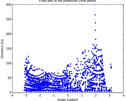
We wanted therefore a development with concave figures. The basic idea is that the protective shape to be delineated (and its two-dimensional projection) can be described by a single concave shape, where its points are of the streamlines. If we calculate the center of the well, and set there the origin of a local coordinate system, the later work can be significantly easier. Further interesting feature is that all streamline points can be represented as polar coordinate point regarding the well center. See Figure 2 for the result.
-4 -3 -2 -1 0 1 2 3 4
0 50 100 150 200 250 300
Polar plot of the protection zone points
Angle [radian]
D
is
ta
n
c
e
[
m
]
The range of the horizontal axis is between -180 and + 180 degrees (between -π and +π), where the vertical
axis contains the direct distance values (in meters) from streamline points to the well center – measured also not along the stream line.
The upper envelope curve of the above polar plot means the highest (maximal) distance, which gives exactly the boundary of the protective area. The development is therefore to find this envelope curve.
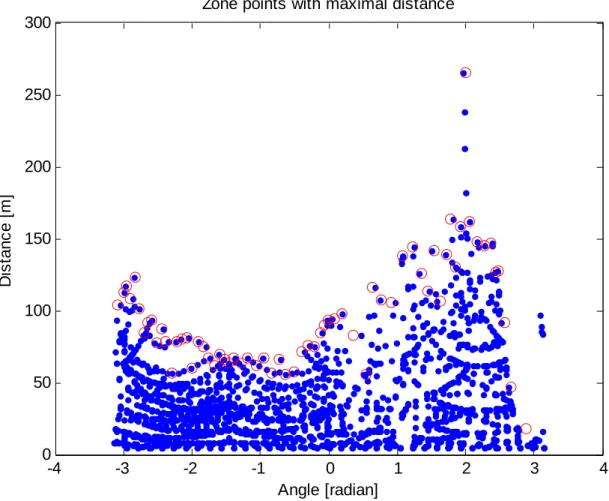
The easiest solution is the use of vertical splits of identical horizontal width, and then the maximal distance of the so segmented points has to be found (Figure 3).
-4 -3 -2 -1 0 1 2 3 4
0 50 100 150 200 250 300
Zone points with maximal distance
Angle [radian]
D
is
ta
n
c
e
[
m
]
Fig. 3: Zone points with maximal distance (marked in red circles)
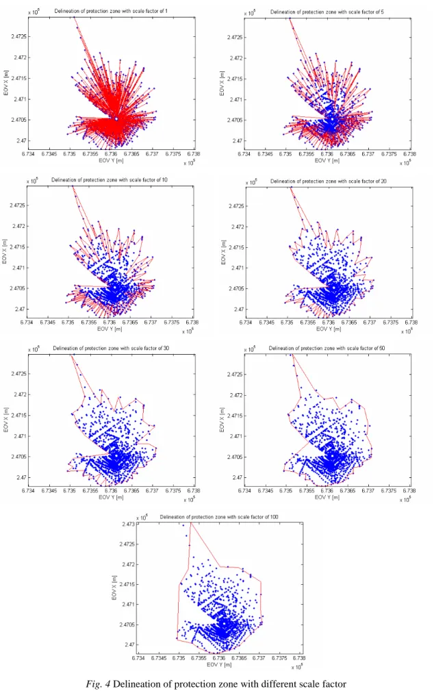
With conversion of these maximal distance points into Cartesian (rectangular) coordinates one can get polygon points. It’s evident, that the width of the splits controls the roughness of the polygon and of the delineation (Figure 4).
The width of the splits can be set empirically.
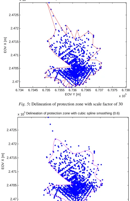
A more esthetical visualization can be obtained by the use of spline interpolation based on the polygon points. In our case an approximation cubic spline with smoothing feature was fit, where the smoothing parameters were suited to the split width. Figure 5 and 6 demonstrates the effect of this smoothing feature. It can be noticed, that a smooth, concave and automatically obtained polygon was achieved. The application of this protection area line can be done even in the field, it’s esthetical in the map, and its area and perimeter is easily calculated. If the points being outside of this area are prohibited, the result can be fine-tuned by the modification of the split width and the spline’s smoothness.
6.734 6.7345 6.735 6.7355 6.736 6.7365 6.737 6.7375 6.738 x 10⁵ 2.47
2.4705 2.471 2.4715 2.472 2.4725
x 105 Delineation of protection zone with scale factor of 30
EOV Y [m]
E
O
V
X
[
m
]
Fig. 5: Delineation of protection zone with scale factor of 30
6.734 6.7345 6.735 6.7355 6.736 6.7365 6.737 6.7375 6.738 x 10⁵ 2.47
2.4705 2.471 2.4715 2.472 2.4725
x 105Delineation of protection zone with cubic spline smoothing (0.6)
EOV Y [m]
E
O
V
X
[
m
]
Fig. 6. Delineation of protection zone with cubic spline smoothing (0.6)
Conclusion
Our aim was to develop such an algorithm which efficiently helps in the automatic delineation of protection zones and protection areas with the determination of a relatively smooth concave polygon. It can be concluded from this article that hydrogeological data can be managed in a mathematical environment, the polygon achieved this way is esthetic and is capable of representation in a map.
The area and perimeter of the polygon determined automatically can be calculated, the coordinates of the breaking points can be output in a file. In case the streamline points located outside of the determined boundary line are not accepted then the solution can be fine-tuned by the zone width of the angles and the smoothness of the spline.
The work continues on the determination and visualization of the protection bodies and protection areas in the MATLAB environment. We would like to investigate the application of further possible methods and
with the individual travel-times, its three-dimensional visualization and the comparison with data stored in other systems can be achieved. Based on the delineated spatial protection bodies the determination of the protection areas associated with the individual travel-times can be achieved.
Acknowledgement
This work is connected to the scientific program of the Development of quality-oriented and harmonized R+D+I strategy and functional model at BME. This project is supported by the New Széchenyi Plan (Project ID: TÁMOP-4.2.1/B-09/1/KMR-2010-0002).
References
[1] Central Directorate for Water and Environment: EU Water Framework Directive, www.euvki.hu, 2008 [In Hungarian] [2] Government Decree No 123/1997 (VII. 18.). on the protection of the actual and perspective sources and engineering facilities of drinking water supply, Budapest, 1997. [In Hungarian]
[3] Government Decree No 33/2000 (III. 17.). on activities that affect the quality of groundwater, Budapest, 2000. [In Hungarian]
[4] Stoyan, G.: MATLAB, Budapest, 2008.
[5] The MathWorks Inc.: Getting Started with MATLAB, Natick, 2001.