Optimizing LLRF Parameters in the Electron-Ion Collider
A Senior Project
By
William M. Bjorndahl
Advisor, Dr. Mastoridis
Department of Physics, California Polytechnic University SLO
Approval Page
Title: Optimizing LLRF Parameters in the Electron-Ion Collider
Author: William M. Bjorndahl
Date Submitted: March 14, 2020
Senior Project Advisor: Dr. Mastoridis
Signature
Contents
1 Introduction to Particle Accelerators and the EIC 5
2 The Acceleration System 5
3 EIC Motivation 8
4 Simulation Results 9
4.1 Direct Feedback . . . 9
4.2 One Turn Feedback . . . 10
4.3 Feedforward . . . 11
4.4 Summary Table of Results . . . 12
4.5 Conclusion: Return on Investment . . . 12
5 Results: Detuning Optimization 12 5.1 No Phase Modulation . . . 13
5.2 With Phase Modulation . . . 14
6 Conclusions 16
List of Tables
List of Figures
1 Contextual information surrounding RF cavities [1]. . . 6a RF Cavity representation as a RLC circuit. . . 6
b Beam pattern delineated as a sine wave. Particles must arrive within the RF bucket, a potential well existing around the stable equilibrium point. . . 6
2 Components of the accelerating system [1]. . . 7
3 Beam Pattern . . . 9
a Time Offset . . . 10
b Klystron Power . . . 10
5 Results of a one turn feedback system. . . 10
a Time Offset . . . 10
b Klystron Power . . . 10
6 Results of a feedforward system. . . 11
a Time Offset . . . 11
b Klystron Power . . . 11
7 Comparing the klystron power of algorithm detuning and manual detuning. . . 12
a Algorithm Optimal Detuning . . . 12
b Manual Optimal Detuning . . . 12
8 Comparing simulated results to expected theory for klystron power without phase mod-ulation. . . 14
9 Comparing simulated experimental results to expected theory for klystron power in pres-ence of phase modulation. . . 15
1 Introduction to Particle Accelerators and the EIC
Ernest Orlando Lawrence won the 1939 Nobel Prize in Physics for inventing the first particle accelerator, the cyclotron, which accelerates particles to high speeds without using high voltage. Scientists initially employed the cyclotron to study the structure of matter, later using it in other experiments when searching for new elements and particles. This technology led to innovations in other fields such as medicine, where Ernest’s brother, John Lawrence, pioneered the field of nuclear medicine by treating leukemia and polycythemia patients with radioactive phosphorus.
Modern particle accelerators follow either a linear (LINACs) or circular (synchrotrons) structure, depending on the application. Synchrotrons use an electric field to accelerate a particle and a magnetic field to steer it. By adjusting the magnetic field strength, the particle orbit stays the same as the particles accelerate. This leads to an increased particle collision frequency, providing researchers with more abundant data compared to experiments using LINACs.
This report will discuss the design of the acceleration system’s feedback loops for the Electron-Ion Collider (EIC) which accelerates electrons and ions at high speeds in a circular fashion. Experiments will run at the EIC for years at a time with occasional maintenance and upgrade periods. Brookhaven National Laboratory (BNL) will build the EIC to:
• Capture the three-dimensional structure of protons and nuclei
• Study the mystery of proton spin
• Search for gluon saturation and the color glass condensate
• Solve the quark and gluon confinement problem
2 The Acceleration System
We used feedback loops to regulate the accelerating voltage that acts on the beam of particles. Cou-pling the beam and cavity interaction allowed us to study and optimize this system.
To energize particles optimally, the molecules must arrive in the RF cavities at a proper time known as the synchronous position. Occurring at an equilibrium point, a black dot represents the synchronous position in Figure 1b. The stable region around the synchronous position, referred to as the RF bucket, contains billions of particles that follow a normal distribution.
To summarize, the RF system serves three purposes:
• Add energy to the beam
• Compensate lost energy from radiation
• Create an RF bucket
RF cavities function as RLC circuits, building up large voltages at their resonance. The field inside the cavity oscillates at resonant frequency. Beam particles must arrive at the proper time to feel the effects of the RF cavity.
(a)RF Cavity representation as a
RLC circuit. (b)the RF bucket, a potential well existing around the stable equilibrium point.Beam pattern delineated as a sine wave. Particles must arrive within
Figure 1:Contextual information surrounding RF cavities [1].
the beam energy, affecting the beam dynamics. Therefore, the beam’s current directly impacts the cavity voltage, prompting coupled-bunch instabilities.
Figure 2:Components of the accelerating system [1].
The LLRF system contains three components.
• Beam parameters
• High Level RF settings
• LLRF parameters
BNL will set beam parameters for the EIC based on the theoretical limits and goals of the project. To optimize the operation, we adjusted high level RF settings such as the detuning, quality factor Q, cavity voltage, and klystron forward power. These settings directly impact LLRF parameters, such as direct loop gain, phase, and delay.
feedback gain by acting on the revolution harmonics. For both of these cases, the feedback systems sample the cavity voltage and act back on it through the klystron. The last case investigated, feedforward, samples beam position instead of the voltage, acting on the cavity voltage through the klystron.
We also examined the effect of the cavity reference voltage phase modulation on the feedback system. In the EIC, phase modulation reduces klystron power by modulating the cavity phase according to the beam transient beam loading [3].
3 EIC Motivation
Optimizing the LLRF parameters in the EIC involves analyzing the trade-off between performance and stability of the beam.
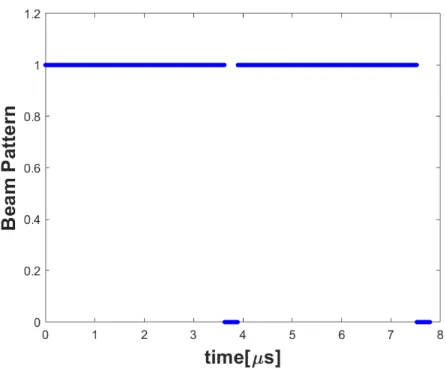
Figure 3:Beam Pattern
4 Simulation Results
4.1 Direct Feedback
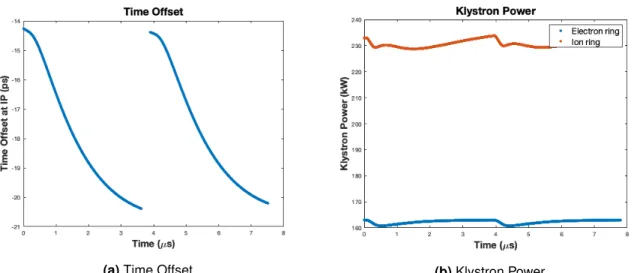
(a)Time Offset (b)Klystron Power
Figure 4:Results of a direct feedback system.
4.2 One Turn Feedback
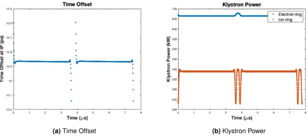
We incorporated a OTFB into the system that increases the gain around the revolution harmonics. This reduces the transient beam loading and effective cavity impedance [4]. Introducing a realistic klystron bandwidth does not change the performance of the passive RF feedback because a closed loop cavity response filters the beam transient. Figure 5 shows the peak-to-peak time offset (3.4 ps with a standard deviation of 0.48 ps) and the required power.
(a)Time Offset (b)Klystron Power
4.3 Feedforward
The feedforward system samples the position of the particles instead of the accelerating voltage. It then adjusts the accelerating voltage to minimize any excursions from the ideal position. In the EIC, feedforward performs better than direct feedback and OTFB but at a higher power cost.
The initial study used an ideal klystron, responding instantaneously to the feedback drive. In reality the klystron response will be defined by the klystron 3 dB bandwidth of about 4 MHz. Considering a short time scale of interest, the bandwidth will affect the wideband klystron. We introduced a realistic klystron bandwidth in the simulations for a more accurate representation.
Figure 6 reveals the peak-to-peak time offset (0.54 ps with a standard deviation of 0.0253 ps) and the required power. Using the same algorithm as the previous systems to find optimal detuning leads to a gap in the beam that requires much more power than expected. Through manual checking, we found an optimal detuning value of -15.4 kHz minimizes energy usage.
(a)Time Offset (b)Klystron Power
Figure 6: Results of a feedforward system.
(a)Algorithm Optimal Detuning (b)Manual Optimal Detuning
Figure 7: Comparing the klystron power of algorithm detuning and manual detuning.
4.4 Summary Table of Results
IP offset pk-pk (ps) IP offset (ps) Peak power electrons (kW) Peak power ions (kW)
Direct Feedback 6.11 1.97 1.63e5 2.33e5
One Turn Feedback 3.42 0.4831 1.73e5 3.10e5
FeedForward 0.5448 0.0253 1.63e5 3.99e5
4.5 Conclusion: Return on Investment
Three possible remedies were presented to mitigate gap transients in the EIC. Section 4.4 summarizes the results for each feedback system. The direct feedback system performs similarly to the OTFB, at a reduced power cost. The feedforward system achieves better performance, but at a greater power requirement.
5 Results: Detuning Optimization
We investigated the relationship between power and detuning to minimize the klystron power con-sumption.
To calculate power with detuning, we used [5]
Pg = 1
2(R/Q)Qext|Ig|
2. (1)
Ig represents the instantaneous beam current, dependent on detuning. Its value will vary based on phase modulation usage in the accelerating system. We examined the cases of no phase modulation and phase modulation in Section 5.1 and Section 5.2.
R/Qrelates the cavity stored energy to the maximum accelerating voltage of the particle. This value
relies on the geometry of the system and exists independently of the RF frequency. The coupler quality factor, Qext, transforms the cavity quality factor as experienced by the klystron in the presence of a
coupler.
5.1 No Phase Modulation
When the beam passes through the klystron, we determined the instantaneous current by
Ig,beam=
Vo 2(R/Q)
✓ 1 Qext + 1 Q0 ◆
+Ipeak
2 Fbcos ( b) i
Ipeak
2 Fbsin ( b) +
Vo f
fRF(R/Q)
. (2)
When absent in the klystron, we measured the current through
Ig,no beam=
Vo 2(R/Q)
✓ 1 Qext + 1 Q0 ◆ +i
Vo f
fRF(R/Q)
. (3)
The parameters found in Equation 2 and Equation 3 define the klystron current. The cavity voltage,
V0, modulates the beam energy that affects beam dynamics.Q0reflects the cavity quality factor andIpeak signifies the peak current of the beam. The relative bunch form factor,Fb, relates to the bunch spectrum component at the RF frequency. Figure 1b displays the phase we want the beam to arrive within the RF bucket, b. Known as the synchronous phase angle, it relates to the bunch energy loss. frf denotes the RF frequency, dependent on the particle (electron or ion) the system accelerates.
In Equation 2 and Equation 3, f represents the detuning. We detuned the cavity halfway,
f = IpeakFbsin ( b)fRFR/Q
4Vo ⇡
9kHz (4)
This keeps the generator current amplitude constant throughout the turn, minimizing peak power.
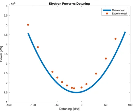
Figure 8: Comparing simulated results to expected theory for klystron power without phase modulation.
Due to the transient behavior between periods of beam and no-beam, the power over a turn will never flatten out to a constant value. Instead, Figure 8 illustrates a vertical shift in the experimental power compared to the theoretical value because of the frequent transients during the switch from beam to no-beam. The simulations resemble the actual condition of the EIC since transients will appear.
5.2 With Phase Modulation
Ig =
Vo 2(R/Q)
✓ 1 Qext + 1 Q0 ◆
+IdcFbcos ( b) +i
IdcFbsin ( b)
Vo f
fRF(R/Q)
. (5)
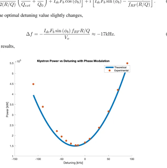
Similarly, the optimal detuning value slightly changes,
f = IdcFbsin ( b)fRFR/Q
Vo ⇡
17kHz. (6)
Plotting the results,
Figure 9: Comparing simulated experimental results to expected theory for klystron power in presence of phase modulation.
Figure 10:Theoretical and experimental results with and without phase mod-ulation.
6 Conclusions
The EIC will collide electrons and ions at high energies. Precise control of the accelerating voltage and thus particle beam is essential and motivated this work. We investigated different feedback implemen-tations to control the accelerating voltage and examined the klystron power and beam phase for each case. Enacting feedforward yielded the best interaction point peak-to-peak time offset and highest power consumption. Direct feedback and OTFB performed similarly, with the latter using slightly more power. We studied the reduction of klystron power consumption through detuning optimization. As shown in Figure 10, cavity phase modulation reduced power usage. This plot also visualizes the relationship between our experimental data with the theoretical models derived in Section 5.
References
[2] Feedback. Merriam-Webster, 2012.
[3] T. Mastoridis, P. Baudrenghien, and J. Molendijk. Cavity voltage phase modulation to reduce the high-luminosity Large Hadron Collider rf power requirements.Phys. Rev. Accel. Beams, 20:101003, Oct 2017.
[4] T. Mastoridis, P. Baudrenghien, and J. Molendijk. LHC One-turn Delay Feedback Commissioning. May 2012.
![Figure 1: Contextual information surrounding RF cavities [1].](https://thumb-us.123doks.com/thumbv2/123dok_us/8222192.2179877/6.918.145.770.640.787/figure-contextual-information-surrounding-rf-cavities.webp)
![Figure 2: Components of the accelerating system [1].](https://thumb-us.123doks.com/thumbv2/123dok_us/8222192.2179877/7.918.237.668.235.592/figure-components-of-the-accelerating-system.webp)