Waste Gasi cation
Final Design Review, 5 December 2019Sponsor: Tod duBois
Mechanical Engineering Department
California Polytechnic State University
San Luis Obispo, 2019
Project Members:
David McCallum [email protected] Glyn Lewis
[email protected] Nash Taylor
[email protected] Nicholas Ordonez
Table of Contents
Safety Disclaimer 4
Abstract 5
1. Introduction 6
2. Background 6
3. Objectives 8
4. Concept Design 11
1. Ideation 11
2. Implementation 13
5. Final Design 17
1. Introduction to the Final Design 17
2. The Mini-Keg Tank 18
3. The Plate Features 19
4. Piping, Valves and Testing Components 19
5. Fastening and Weld Designs 20
6. Gas Cooling and Controls 20
7. Summary of Design and Cost Breakdown 21
8. Alternative Design for Testing 21
6. Manufacturing 22
7. Design Verification through Testing 24
8. Project Management 26
1. Planned Purchases 28
2. Planned Analysis 28
3. Planned Initial Testing 28
4. Final Testing Plan 29
9. Conclusion 29
List of Figures
1. The GEK waste gasifier from All Power Labs 7
2. Wastebot Gasifier 8
3. Original proposed testing environment 9
4. Characteristics of Fixed Bed Gasifiers 10
5. Top Fed Up Draft Gasifier 11
6. Initial ideation drawings of suggested chamber designs 12 7. Weighted decision matrix judged against the existing wood gasifier found on YouTube 13 8. Lamtor 128-oz “mini-keg” courtesy of the Amazon sales page 14 9. Initial CAD model of the mini-keg chamber for design consideration 14 10. Demonstration of the secondary door chamber configuration for design consideration 15 11. Isometric view of the proposed safety housing of the mini-keg gasifier system 15 12. Cross section of brick and keg system to demonstrate thickness expectations 16
13. Concept Prototype 16
14. Isometric of desired final design at CDR stage 18
15. Final mini-keg gasifier model for testing 22
List of Tables
SAFETY DISCLAIMER
The IGT team and California Polytechnic State University take no responsibility for any actions taken with this or any future gasification device based on IGT team research. The IGT team does not recommend use of this gasification device in this configuration due to testing concerns and incomplete safety constraints.
Abstract
Chapter 1: Introduction
The sponsor, Tod duBois initially pitched the idea of a waste to energy gasifier. Gasification is the process of superheating organic compounds to high temperatures in order to break chemical bonds to release hydrogen and carbon monoxide gas. This gas then can either be used as a fuel, burned in a chamber, or saved for any other purpose. Current gasifiers mostly use wood logs or pellets as fuel and cannot handle many forms of municipal waste. Not only are there limited fuel sources for many common small scale gasifiers, but they are also very expensive. We set out to prove that a small scale gasifier could be built easily and cheaply, while also being able to handle a variety of fuel sources. The scope of our project ended up being narrowed, as we eventually only decided to test our gasifiers operation with a known wood chip fuel source, as opposed to municipal waste.
Chapter 2: Background
Gasification is the process of converting some type of bio-fuel into a combination of carbon monoxide, hydrogen, and carbon dioxide known as synthetic gas, or syngas. Syngas is produced by heating, without combusting, bio-fuel substances to temperatures above 700 °C. The syngas can be very useful as a fuel because its higher combustion temperature can make it more efficient than the original fuel. This process has the potential to be a very effective and environmentally friendly source of energy in the future.
Currently, multiple examples of gasifiers exist on the market. All Power Labs has created a system called the Gasifier Experimenter’s Kit ( GEK) that is a continuous gasifier that uses wood chips to directly produce electricity [5]. However, their system is large, extremely loud and can only operate with very dry wood chips. Another example of a current gasifier on the market is made by Atmos [6]. This gasifier works with standard wood logs but runs only on batches and produces heat instead of electricity.
Figure 1. The GEK waste gasifier from All Power Labs
There is an ongoing search for a better, greener source of power. Solar energy is great for large scale operations in sunny conditions, but for people living in cloudy areas off the grid, there are not a lot of renewable power sources. Gasification could be a solution to this problem. By superheating the wood instead of burning it, the amount of harmful greenhouse emissions is greatly reduced. In addition, if the system was small and robust, it could be portable and affordable. Overall, creating a continuous, pressurized gasifier that can operate with multiple input materials would be a breakthrough in power generation.
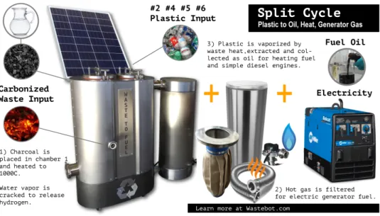
Figure 2. Wastebot Gasifier
Chapter 3: Objectives
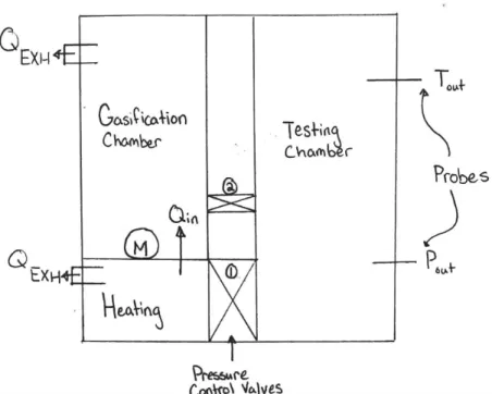
Figure 3. Original proposed testing environment device with three chambers demonstrating the gasification, testing, and burning chambers that allow the gas to be processed with little remaining exhaust. The temperature and pressure probes would detect values from the testing
chamber ideally with no leakage.
The team interviewed sponsor Tod duBois on January 17, 2019 receiving information about his long-term goals with the project. This information is summarized in the chart below. The initial scope of work was much too large to be done in a 1 year timeline, so the team had to narrow the scope.
Table 1. Tod duBois needs and wants [7]
Needs Wants
Cost-effective creation and assembly Applicable to current hardware (Keg) Sustainable heating of the waste Transferable heat from syngas
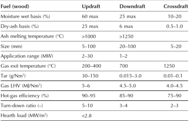
Figure 4. Characteristic table of fixed bed gasifiers
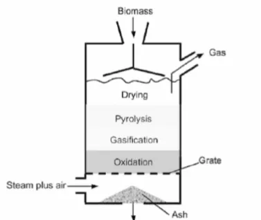
Figure 5. Demonstration of standard, top-fed, up-draft gasifier
Chapter 4: Concept Design
The primary goals for the team are to provide the sponsor, Mr. duBois, with a proper testing apparatus to demonstrate the real-world viability of a home-use, multi-material waste gasifier, and ensure proper safety of the system within this use case. For that purpose, the IGT Team applied their current understanding of the physics behind the process and allocated the first two major concerns, high temperature and pressure. Much of the research supporting the team so far has determined that the operating conditions will be in the maximum temperature and pressure range of about 2000℉ and 1 atm, respectively. Since this system deals with multiple low density gases that may drastically increase in pressure as the system is heated and the gasification process begins, the team made pressure control a primary concern to maximize safety. Furthermore, the system needs to be robust enough to handle the multiple types of materials that would be gasified within it, and consistently reusable to allow the testing of multiple runs worth of varied materials. As this is privately-funded endeavour, cost and manufacture concerns exist and present further challenges to the design. Lastly, the ultimate success of the device’s design will be due to the speed at which it will gasify material and ease of subsequent maintenance.
Section 4.1: Ideation
that the location and material used to heat the device and cause gasification could be anything from propane to electric heating. As seen in Figure 6, the initial designs took guidance from Mr. duBois’ original idea to use stainless-steel beer kegs. The design attempted to branch off it and evolve into smaller kegs. This design choice is discussed in greater detail later. Following the period of ideation, the most-viable ideas were sorted, and broken down based on their successful components. From there, the five ideas that were voted best were placed into a weighted decision matrix and were compared to a homemade gasifier as presented on YouTube, which can be seen on citation 10. This system uses widely available metal components welded together to gasify wood and convert it into a fuel for use in a generator [10]. The results of the decision matrix may be seen in Figure 7. Following this exercise, the team chose their most viable designs which were found to be the horizontally-oriented, coal-heated, mini-keg design, and the vertically-oriented, electric-heated, mini-keg design, however, due to further discussion and voting on the future of the project, the most-liked design was the vertically-oriented, coal-heated, mini-keg. While the horizontal design would be more effective and easier to clean, the existence of a moving component and a cut point, as well and necessary welds was extra complexity that the team was uninterested in pursuing. Additionally, electric heating could have been a very successful design choice, but is far more expensive than organic heating and much more difficult to implement, especially for people without strong home electric grids.
Figure 7. Weighted decision matrix judged against the existing wood gasifier found on YouTube
Section 4.2: Implementation
For the purposes of both eliminating difficulty in design and allowing adaptability for the sponsor, the IGT Team eventually decided upon a smaller “mini-keg”. Since it is made out of stainless steel, it should sustain reasonable thermal and pressure loading, but will still require further testing to prove. The ‘mini-keg’ holds 128 oz compared to 1984 oz. Furthermore, this early decision allowed the team to push forward with design choices and considerations with this as the main chassis. In essence, the mini-keg is a considerably smaller scale standard beer keg made of food-grade stainless steel. Originally, the team had chosen a device by ManCan, however Figure 8 presents the option the team decided on from Amazon produced by Lamtor for about $40, though other options are available with varying prices and sizing options. While not a perfect sample of material, being so convenient to source allows it to be the best option for a cost-effective build, and future testing will determine its viability for the final deliverable build and could demonstrate the possibility of its implementation in a future iteration of this project.
Figure 8. Lamtor 128-oz “mini-keg” courtesy of the Amazon sales page [11]
Figure 9. Initial CAD model of the mini-keg chamber for design consideration
Figure 10. Demonstration of the secondary door chamber configuration for design consideration
The final major consideration made was around accommodating for safety compliance while also meeting the temperature and pressure requirements. If the tank is kept vacuum sealed below one atm and the gasified material is controlled with pressure valves to maintain that pressure, the small amount of material gasified would not pose a harm of a rapid pressure release explosion. Furthermore, as presented in Figures 11 and 12, the team will account for the high temperature requirement by enclosing the structure in high-temperature fire bricks which should keep the general area safe in case of a tank breach. The final consideration is the toxicity of material in gasification which should be controlled by using small amounts of material in the gasifying process.
made with fire-bricks, the can will use a mini-keg, as discussed earlier, and the straws will be a thermal and pressure comprehensive material, perhaps stainless steel pipe.
In review, the IGT Team examined a great deal of testable designs for this gasification exercise, but the final decision fell to the safest and most simple-to-manufacture design of the mini-keg gasifier with enclosure. If handled correctly, this platform should produce a versatile and long-last tank system to allow for the testing of a plethora of different materials in the future.
Chapter 5: Final Design
Section 5.1: Introduction to the Final Design
The final implementation of the mini-keg gasifier is a truncated version of the final assembly. The plate feature was removed due to welding constraints. The team instead chose to implement an automotive V-band clamp to connect the bisected keg. For future designs, thicker material should be used so the keg can be welded to the plates and provide a stronger system. Additionally, the IGT team could not weld the outlet pipe into the system, so a clay molded housing was used for cost reasons. The last change made omitted the cooling trough, as it was not necessary for the revised testing.
Due to safety concerns, the team was forced to create a new iteration of the total assembly from the Preliminary Design Report. Originally, the necessary components included a bisected mini-keg purchased from Amazon; one four foot long stainless steel pipe with a 1.5 inch diameter and two stainless steel plates specially designed and manufactured for this project. Additional hardware required include eight stainless steel nuts and bolts at 0.25 inch thread diameter, with relatively nominal length requirements (the stainless plates are 0.030 inch thick each meaning total bolt length must be at least 0.1 inch, well below many the smallest, affordable, wholesale bolt lengths).
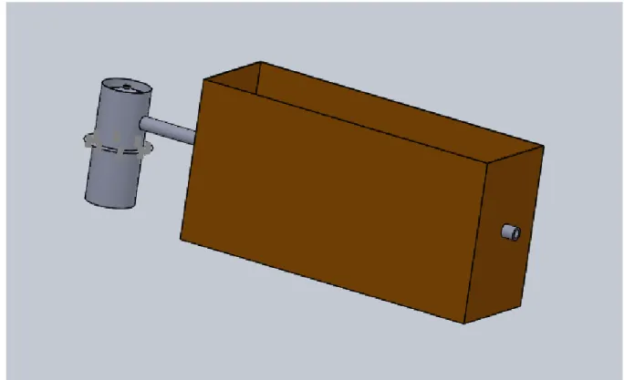
The final iteration of the tank will omit the original oxygen inlet pipe as well as the plate feature. As a result, the internal chemical reaction will be limited by the amount of oxygen left in the tank once it is capped. In addition, the new assembly configuration will include a four foot exhaust pipe that will run through a cooling trough filled with water. After analyzing the chemical products and their behaviors under the expected temperatures, the team calculated that fourteen gallons of water will be necessary to cool the exhaust gas to a safe temperature range of 150-350℉. This will require a large wooden trough with dimensions 3 x 1 x 1.5 feet to hold the water. Figure 14 shows the new total assembly.
more difficult to weld than other steels. As far as testing, the uncertainty around control for longevity and safety requirements as specified in the safety section means that thermal testing must occur at exit flow to ensure that the system is indeed operating as intended.
Figure 14. Isometric of desired final design at CDR stage
Section 5.2: The Mini-Keg Tank
Section 5.3: The Plate Features
The plate feature is a simple design for attaching the two halves of the bisected mini-keg in order to create a pressure-seal. This design also allows the system to be dismantled for cleaning of gasification byproducts. The plates are roughly 3 inches larger in major diameter size than the main tank, a feature defined for the bolt heads exclusively, and likely unnecessary to scale larger for the larger keg system. Each of the plates is given an internal cut that is intended to be slightly smaller than the diameter of the main tank body, in this case about five inches. This slight covering should allow for better welds along the surface of the tank, a necessity for this design’s safety. Eight 0.25 inch holes will be cut in a roughly equidistant circular pattern where tolerance on location is not essential as they are for providing a strong seal of the tank.
The plate features may be seen in the exploded view in Figure 15 or in the drawings in the Appendix D.
Section 5.4: Piping, Valves, and Testing Components
The top tank half is cut with a 1.5 inch diameter for pipe flow outlet of gases from the system. The gasification process does require some oxygen into the system to operate, so the final design does not allow for continuous operation. The gas will flow into the exhaust pipe, through the cooling tank and to the open environment. There will also be a carbon monoxide monitor at the end of the pipe. If the monitor goes off during operation, then the team will know that the system is successfully gasifying.
Within each of the pipes, the gases will be operating at their source temperatures and pressures, which is ambient temperature and standard pressure for the air inlet in the bottom, and gasification temperature and tank pressure out of the top. Initially, the team planned to include valves in the piping. Due to the inability to find an affordable valve that would operate at the expected temperatures, this component was omitted. In order to prevent combustion of gasification products, the gas must be cooled to a safe temperature. This is done with the inclusion of the cooling trough. If the gas is being combusted, then the pipes need to be long enough to avoid damage to the gasification tank, but not too long that the flow damages the pipes. For this model, the pipe is roughly four feet long, which will be cut to length on a cold saw or other abrasive manufacturing process as necessary from wholesale purchase.
Section 5.5: Fastening and Weld Designs
The entire keg-gasifier system must be fastened and welded at all breach locations to create a pressure seal, allowing the gasification process to work. This seal will be achieved with fillet welds along all cut-and-connected surfaces, in essence the plate features and piping to the tank halves. The difficulty of the welds must be acknowledged before manufacturing because as-designed, the system requires stainless steel welds (likely through TIG processes) on plating no more than about 0.03 inch thick, depending on the thickness of the purchased mini-keg. This is likely to be the most expensive part of the manufacturing process, as it will require a highly experienced welder. Therefore, within the scope of the design, welds were avoided unless absolutely necessary. The welding diagram in the Appendix D presents all these features.
The releasable seal component requirement necessary to clean the tank after gasification will be held together by bolts on the plate features demonstrated in Figure 14. These bolts and nuts will likely only need to be 1 inch in length due to the plate features having a combined thickness of 0.06 inches. The longer the bolt, the greater the cost, but the team is examining options and will be testing bolt reliability at thermal load, which will help decide the final choice of fastener. The general estimate of the cost is no more than about $15 for bolts and $10-15 for nuts of equivalent mated size.
Section 5.6: Gas Cooling and Controls
The cooling of the gas, determined by the size of the water trough demonstrated in Figure 14 is integral to the final successful operation of the design. Through calculations of the heat transfer rate from the pipe, defined by equation 5.1, juxtaposed against the assumption of maximum heating of the water at boiling point (equation 5.2), the maximum volume of water needed for 3 feet of straight pipe was determined to be about 6 cubic feet. This would allow the gas produced to be cooled to around 250 ℉, well below the safe requirements for gas operation. Additionally, the assumptions made around this calculation, such as maximum heating of the water, introduce a factor of safety to the system. If this proves to fail in testing, then the simple conclusion is just to add more water or pipe.
UAΔT
Section 5.7: Summary of Final Design and Cost Breakdown
The final design is an amalgam of the original plans for prototypes made throughout the Senior Project quarters to date. The only major manufactured component is the plate feature which will be manufactured under specifications in Chapter 6. The raw stainless steel for the plates will be roughly $50, purchased from whichever wholesale retailer is most affordable at the time. Cutting these plates will produce negligible cost, as the IGT Team will manufacture themselves. However, if this feature is to be further implemented, the IGT team recommends accounting for cost of manufacturing at proper scale. Plasma cutting or waterjet cutting could be efficient and affordable forms of manufacture for this feature. From there, stainless steel piping is required to route the gas away from the tank and heat source. Testing materials, such as a carbon monoxide detector, and safety materials, such as the fire bricks, will likely add about $50 and $40 to the total system as needed.
The final cost of the system is therefore conservatively estimated to be about $300, which may change due to the fluctuating cost of components and the uncertain estimations of manufacturing cost. The total cost is unlikely to be much more expensive than expected because the IGT team calculated expenses with shipping included for each, and under most-expensive manufacturing situations.
The system’s materials purchase breakdown can be seen in totality in the Bill of Materials filed in the Appendix E.
Section 5.8: Alternative Design for Testing
The model of the mini-keg gasifier proved more difficult to manufacture than expected, as explained in the manufacturing chapter. The IGT team decided to attach all testing components to the mini-keg using more conventional, if less effective, means.
The plate feature was unable to be welded, so the team purchased a stainless steel V-band clamp for $15 to attach the two halves of the keg. The clamp provides an imperfect seal, and is not recommended for larger-scale devices or critical gas testing scenarios.
Additionally, the piping was unable to be welded, so high-temperature clay was used to provide a funnel seal to the piping, routing the gas away from the gasifier. As the gas flow did not contain high pressure, this seal was effective and safe, but proved flimsy and prone to failing just by moving the gasifier. Continuing on, this seal should be replaced with a stainless steel pipe coupling.
Figure 15. Final mini-keg gasifier model for testing
Chapter 6: Manufacturing
The goal is to divide the greater system into manageable, manufacturable components, and allow for the defined subassemblies to be tested individually and constructed simultaneously. The original system had three major subassemblies: the top half of the keg, bottom half and a wooden trough for heat transfer. The top half of the keg was designed with a 1.5” hole cut for the exhaust pipe. The bottom half is simply half of a keg shell with a flange welded on. The trough, which was omitted for the final prototype, is a plywood box sealed and caulked to minimize water leakage.
safe temperature range of 150-350℉. This will require a large wooden trough with dimensions 3 x 1 x 1.5 feet to hold the water. For our small scale model, the team did not feel the need to include the cooling container during testing. Instead, the team inserted the exhaust pipe into the top of the hole of the keg’s upper half. It was held in place and sealed using moldable clay.
The team’s tentative manufacturing plan is the following:
Step 1- Order Parts
See Bill of Materials in Appendix E for lists and prices. Intended purchases include raw steel, stainless steel pipe, fasteners, and mini-keg.
Step 2- Cut keg in half [Top Half of Keg & Bottom Half of Keg Drawings in Appendix D]
The team used an angle grinder to bisect the keg. Then, the keg edges were smoothed down using the bench grinder. The final tolerance on the cut is unimportant, but must be done in a non-intrusive method in order to prevent damage (bend, warp, melt) the two bisected components.
Omitted: Step 3- Cut Holes for exhaust [Top Half of Keg & Bottom Half of Keg Drawings in Appendix D]
Use a hole saw to cut hole in top half of keg. If the team cannot find a hole saw for metal at the machine shop the team may need to find other manufacturing techniques such as plasma cutting or laser cutting. Some major constraints include correct tolerance, to allow the pipe to be correctly welded without damaging the system as a whole.
This step was omitted from the manufacturing process. The top hole that came with the unaltered keg was used for exhaust.
Step 4- Manufacture flanges - cut into correct shape and drill holes for bolts [Plate Feature Drawing in Appendix D]
The team was able to program the waterjet to cut the stainless steel sheet metal and the equally spaced six holes.
Omitted: Step 5- Weld on flanges [Plate Feature and Welding Diagram Drawings in Appendix D]
outsource the welding to qualified Cal Poly shop technicians. If the welded flanges do not create a good enough seal the team will research and purchase an O-ring or gasket.
Due to the thin walls of the keg, the team concluded that they could not successfully weld the flanges to the keg halves without compromising the structure of the system.
Step 6- Cut exhaust pipe
The team was able to cut the 1.5” diameter exhaust pipe with an angle grinder.
Step 7- Attach exit pipes to keg [Welding Diagram Drawing in Appendix D]
The team was able to place the exhaust pipe through the top hole in the keg. Molding clay was used to hold it in place and create a tight seal to keep the gasses from leaking.
Omitted Step 8- Manufacture Cooling Trough
The 3 x 1 x 1.5 foot plywood trough will be be nailed together. The connecting surfaces will be caulked in order to prevent any leakage.
Chapter 7: Design Verification through Testing
The purpose of this section is to summarize the testing methods of the keg-based gasifier. Initially, the main goal of the Senior Project was to test the outputs of gasifying different household wastes. Unfortunately, due to safety concerns from the university, the project’s scope was narrowed to proving the feasibility of gasification in the keg-based system. The testing plan and corresponding dates are as follows:
Build Prototype Mini Keg Assembly to Test Under Extreme Temperature - May 31, 2019
This will be a complete gasifier with all necessary components attached. All manufacturing processes are listed in Chapter 6 of this report.
Test Wood - November 15, 2019
Once the mini keg assembly was manufactured, the team assessed the feasibility of gasification. In order to accomplish this, the team tested with wood chips. Since wood chips are already a proven form of fuel for gasification, if the mini keg assembly is able to produce syngas from the wood, the team will know that the set up is capable of reaching the necessary temperatures. The team placed the system in the orientation shown in Figure 15 with smoldering coals at the center of the brick formation. In addition, a carbon monoxide was placed next to the outlet pipe in order to monitor the production of gas within the keg.
Proof of Gasification - November 15, 2019
For proof of gasification, the team implemented a simple carbon monoxide test at the output nozzle thereby determining if gasification has occurred. Two components of syngas include Hydrogen and Carbon Monoxide; therefore, once the carbon monoxide alarm was set off, the team confirmed that the keg-based system did indeed gasify the wood chips. Primarily, the objective of testing to prove the active production of gasified material was confirmed from this test. Some possible next steps include proving the tank may operate safely over longer periods of time.
Originally, the team had planned to acquire different types of waste and test them in the gasifier in hopes to collect data and run statistical tests to see what materials are feasible energy production sources. Due to the possibility of toxic gases being released during the gasification of the different specimens, the team had to omit these stages of testing. The omitted steps for testing waste are as follows:
Acquire Different Samples For Testing
In order to produce the most accurate data, it will be necessary to dehydrate all of the testing samples to the lowest possible water contents. In order to achieve this, the team plans to collect a variety of household waste and leave them in the sun for prolonged periods of time. Luckily, summer vacation allows the team to use the hottest days to dehydrate materials for free. In layman's terms, the team is going to put trash under the sun to evaporate out the water.
Test Different Compositions of Materials
waste that will be grouped different categories. Initially, the team will add small amounts of this waste to the already tested wood fuel and monitor the change in syngas production using the flow gauges in the exhaust pipes. Depending on the direction of data, the team plans to incorporate more and more waste to the fuel specimens until they test a full batch of waste. If the team sees a decline in the syngas production, they will try waste from a different category. All this data will help the team see which types of waste are feasible for large scale gasification.The reason for the date and following dates being TBD is because the team wants to make sure that they have a perfect system for testing gasification on wood before we proceed. It is difficult to estimate how long this will take the team because there is not much information recorded about how this process is completed.
List of different Tests
As discussed above, the first test will be conducted with strictly wood chips as fuel. As of right now, the team has not begun to collect their waste for gasification. Some different forms of waste that the team plans to test include standard green waste and food waste. Standard green waste will include materials such as grass clippings, sticks, leaves etc. Food waste will be split up into plant food waste and animal food waste. All of the waste will need to be dried beforehand so that there will be no moisture once it is in the tank for testing. The team will attempt to standardize the size of the testing sample in order to get values that are easily comparable.
Summarize Data and Run Statistical Tests to See what Materials are Feasible Energy Production Sources
waste effectively, and that requires a low water content and a reasonable material density. Now this design process is not the team’s main concern so it can be a crude procedure if necessary, but it is essential to successfully complete the team’s next phase. Due to time constraints and safety hazards, the team was never needed to complete this step of the project. The team was very worried that the gasses produced from using household waste would be extremely dangerous and toxic, so the team only used wood chips in the gasifier.
The second design phase will be the small scale testing and gasification of the waste the team produces. Using a miniature keg with a refractory housing, the team plans on creating chamber to test different biomass compounds and mixtures to obtain valuable data. The design process will proceed as follows. A more detailed timeline can be found in the attached Gantt Chart.
● Plan (Completed on 5/2/19)
○ The planning phase has been mostly completed at this date. The team has used brainstorming methods in combination with decision matrix comparisons to determine the overall direction the project will head.
● Design (Completed on 5/2/19)
○ The design process will take place during this upcoming spring quarter. The team will design, with tangible deliverable materials a complete system that has the ability to function theoretically. Most likely using Solidworks and it’s built in thermodynamic functionality, the team will have a well defined blueprint to move forward with the next step in the design process.
○ The teams design that was completed on 5/2/19 was too challenging to manufacture due to challenges in working with stainless steel. The design was modified during Fall quarter 2019.
● Develop & Test ( Completed on 11/5/18)
○ The development and testing period will begin in the fall quarter of the 2019 school year, the last collegiate quarter at Cal Poly for all team members. This will involve taking the groups completed system models from the previous quarter, and completely constructing the design. There will surely be hiccups in the transition from the design to the building phase, but hopefully only ones the team will be able to account for. Once an initial design has been released, the team must test it to prove viability. If the product does not meet the team’s initial desired standards, the project will be tweaked or completely reconstructed. The design successfully worked on 11/5/19.
● Implement
recommend using a keg based gasifier. This design, while cheap and successful, can be very dangerous and could lead to serious health effects.
Section 8.1: Purchases:
● Amazon produced by Lamtor = $42.87 ● 14 10” Firebricks = $46.77
● Stainless Steel tubing and Sheets = $148.39 ● Coal, wood, other supplies = $58.11
Total Purchases: $296.13
Our original goal was to be under $250. The total cost to actually manufacturer the gasifier was much less than this and we therefore achieved our goal. The other costs are for testing equipment and supplies to start the gasification process.
Section 8.2: Planned Analysis:
The most important part of the team’s project is to analyze the feasibility of different fuels in gasification. Unfortunately, the team will not be able to measure quantitative data as expected in the earlier scope. If future teams are to take on extensions of this project, quantitative data can be recorded using either a flowmeter or pitot tube and attach it to the outlet valve, so that they can calculate mass flow rate and total output gas quantities. Additionally, to determine the composition of output gas, the future team can utilize gas spectrometers from the chemistry department to analyze small samples of collected output syngas.
Section 8.3: Planned Initial Testing:
mix of wood pellets and municipal, then move up to 100% municipal waste. If at any point gasification is unsuccessful, the team will record this and attempt to revise a plan to make gasification possible.
Section 8.4: Final Testing Plan
After careful consideration, the team decided to only test the gasifier with wood chips. While this did lead to the successful production of carbon monoxide and therefore gasification, the team did not feel safe to test other materials. With more resources the team does believe they could have successfully gasified other forms of green waste, but with a limited budget and time constraints, gasifying more than would chips could have put team members in danger.
Chapter 9: Conclusion
References
1. Knoef, H.A.M. “HANDBOOK ON BIOMASS GASIFICATION.” BTG biomass technology group BV. www.agronavigator.cz . Accessed 31 January 2019.
2. Arena, Umberto. “Process and technological aspects of municipal solid waste gasification. A review.” Waste Management . Volume 32. Issue 4 . April 2012. www.sciencedirect.com .
3. Gasification of Municipal Solid Waste for Large-Scale Electricity/Heat. www.climatetechwiki.org . Accessed 31 January 2019.
4. McCarley, Art. 22 January 2019. Personal Interview. San Luis Obispo, CA. 5. http://www.allpowerlabs.com/
6. https://www.atmos.eu/en/wood-gasification-boilers/
7. duBois, Tod. 17 January 2019. Personal Interview (phone). San Luis Obispo, Ca. 8. https://wastebot.com/
9. Basu, Prabir. Biomass Gasification and Pyrolysis : Practical Design and Theory, Elsevier Science & Technology, 2010. ProQuest Ebook Central,
https://ebookcentral.proquest.com/lib/calpoly/detail.action?docID=648812.
10. M, JR. “amazing homemade gasifier uses wood pellets to run generator - renewable alternative energy video.” https://www.youtube.com/watch?v=a6e3CprVTi8 . YouTube. 16 March 2013.
11. Lamtor. “ Lamtor G003-3.6L 128 OZ Mini Keg Style Growler Stainless Steel Barrel Holds Beer Silver, 3.6L.”
https://www.amazon.com/Lamtor-G003-3-6L-Growler-Stainless-Barrel/dp/B0777FF2 42/ref=sr_1_6?keywords=mini+keg&qid=1556555012&s=gateway&sr=8-6 .