Evaluating EGNOS technology in an ITS driving
assistance application
A. Gómez Skarmeta* H. Martínez Barberá* M. Zamora Izquierdo* J. Cánovas Quiñonero* L. Tomás Balibrea** (*) Communications and Information Engineering
University of Murcia 30071 Murcia. Spain
(**) Vision, Robotics and Engineering Projects University of Murcia
30071 Murcia. Spain
[email protected] [email protected] [email protected] [email protected] [email protected]
ABSTRACT
The aim of this paper is to present a contribution to the field of Intelligent Transport Systems, concretely in the section of satellite-assisted vehicles. We first describe the MIMICS project, whose goal is to develop a platoon of intelligent vehicles. This project relies on the use of satellite based localisation. For this task we are currently evaluating and using both GPS and EGNOS systems. We present a comparison of these systems, both in static and dynamic use.
INTRODUCTION
The main goal of the MIMICS project is to develop a platoon of intelligent vehicles. To accomplish the goal a series of techniques and technologies are being integrated currently, some of them based on satellite positioning systems [3][1]. The experiments consist on two vehicles equipped with different sensors. The leading one incorporates a collision avoidance system in order to assist the driver and a satellite navigation system in order to help the driver follow the route. The trailing vehicle is to be fully autonomous vehicle. It incorporates an autonomous-driving control software to follow the route covered by the leading vehicle and a satellite navigation system in order to localise and reference both vehicles. To make the system robust, both vehicles work in a cooperative way, in which sensor information, actions and intentions of the leading vehicle, and warning events and alerts are shared between the vehicles. This is accomplished using a wireless network with long range antennas.
In the following sections we introduce the EGNOS system. Then we describe the experimental setup for satellite based localisation and the results obtained in different tests. Finally we present some conclusions.
THE EGNOS SYSTEM
The EGNOS system [7] appears as the European contribution to the GNSS system. This contribution is planned in two stages: GNSS-1, which tries to complement the existing positioning signal in order to compliment the aeronautics standards, and GNSS-2, which consists in a constellation of European satellites under civil control called GALILEO that is planned to be fully operative in 2008.
EGNOS includes what is called SBAS, a set of techniques to improve the existing global positioning methods (GPS/GLONASS). SBAS systems are based in constellations of geostationary satellites, which complement the existing ones. EGNOS is intended to be compatible with other SBAS systems such as WAAS (USA) and MSAS (Japan) in order to have a global coverage with SBAS improvement system (this is very important in aeroplanes).
A major EGNOS goal is to improve the quality of the positions calculated with the existing positioning systems, and thus it provides:
• Better accuracy than GPS and GLONASS alone.
• Guaranteed availability.
• High integrity.
• Continuity of service.
EGNOS provides three main functions to deal with the previous requirements:
• GIC: broadcast of integrity status of satellites to users. Improves integrity
• WAD: delivery of clock, orbit and iono corrections to the users. Improves accuracy
• Ranging: transmission of GPS-like signals from the GEO satellites. Improves continuity and availability
A SBAS method consists basically in collecting raw data from the GPS/GLONASS constellations and from the geostationary satellites, computing an augmentation message and boadcasting this message to the users through the GEO satellites. In the EGNOS case (the EGNOS space segment) the following geostationary satellites are used: AOR-E and IOR (INMARSAT) and ARTEMIS (ESA).
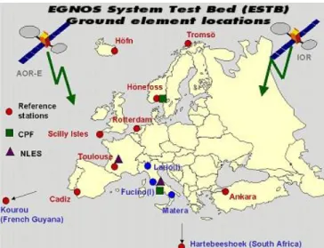
Currently, the EGNOS system is on a test stage with a prototype which consists in the pre-operational EGNOS signal-in-space. The EGNOS System Test Bed (ESTB) objectives include not only supporting EGNOS system development and verification but also demonstrating EGNOS to its potential user communities, preparing for its future operational introduction. At this moment the GLONASS signal is still not used for SABS. The ESTB signal (Figure 1) has since mid-February 2000 been transmitted from space, and is intended to be fully operative in 2003.
The EGNOS system consists on the space-segment described previously and a ground-segment, which consists on Reference Stations (RS), Processing Centres, Navigation Land Earth Stations (NLES). The system relies on a communication network that connects each reference station to a processing facility for the purpose of data collection and remote monitoring and control of the reference stations. These processing centres are connected to suitable NLES for the uplink to AOR-E and IOR, and in this way the NLES are the connection between the ground-segment and space-segment.
Figure 1: The EGNOS System Test Bed.
GPS AND EGNOS EXPERIMENTS
EXPERIMENTAL SETUPClearly, localisation plays a central role in the MIMICS system, both for human driver assistance and for computer based driver. Human driver assistance is especially suitable for localisation in unknown industrial areas and cities, while satellite localisation improves the platoon formation and the
vehicle route following tasks for the computer-based system. We are currently evaluating different satellite based technologies and alternatives [2]: differentially corrected standard GPS receivers (Trimble ACE III) and EGNOS based receivers (Novatel Millennium GPSCard).
The Novatel Millennium GPSCard [5][8] is a high-performance GPS receiver capable of receiving and tracking the L1 C/A-code, L1 and L2 carrier phase and L2 P-code of up to 12 GPS satellites. Besides, the receiver can operate with a differential GPS, accepting RTCA messages in order to incorporate corrections from a reference station.
To improve the accuracy, integrity, and availability of the basic GPS signals, the system can use WAAS/EGNOS signals. It can incorporate the corrections provided from these systems to generate differential-quality position solutions. It permits two user-configurable options: 12 GPS or 10 GPS and 1 WAAS/EGNOS L1 channel. The first option is called single-point mode, in which positions are computed directly from the GPS satellites, and thus, the Novatel receiver works as a standard GPS receiver with a time based filter. The second option is called WAAS mode, in which the GPS signal is enhanced with the EGNOS signal in order to compute positions.
The antenna used with the receiver is capable of receiving L1 signal with the following features:
• L1 centre frequency at 1575.42
• Enhanced multipath rejection.
• Internal low noise amplifier (active)
• Low noise figure
The Trimble ACE III GPS [6][9] receives the L1 frequency C/A signals of up to 8 satellites, and can obtain and accuracy of 25 m without SA. It can also receive RTCM SC-104 messages in order to make differential corrections and get 2-meter accuracy.
Differential correction is achieved by way of a RASANT protocol receiver, which is directly plugged into the ACE III. This device accepts the RDS (Radio Data System) signal from RNE-2 (Radio Nacional de España, channel two), a public FM radio station that broadcasts RTCM SC-104 messages. The device extracts messages from the RDS signal and passes them to the GPS receiver, which interprets them and incorporates the corrections into the positions.
In this case the system uses two antennas: one is an active antenna which receives the L1 signal and the other is a standard FM radio antenna which receives the RDS signal. Two different types of tests have been performed. First, static tests have been conducted in order to obtain statistical figures (average and standard deviation). In this case the antennas were located in the same fixed location on the roof of our Faculty. Data acquisition has been performed in different days and during different periods of time. Second, dynamic
tests have been conducted in order to verify the in-motion accuracy of the receivers. In this case the antennas were located in a fixed location on the roof of a car. Data acquisition has been performed in the perimeter road of our University campus. The car velocity was kept between 35 and 50 Km/h during most of the time, slightly decreased in roundabouts and junctions. The paths obtained with the two receivers are plotted on a custom GIS (Geographic Information System) [4]. The map contained in the GIS has been obtained manually from a differentially corrected GPS by running the road lanes at human walking speed.
The following subsections present the different tests that have been conducted and some statistical results.
COMPARISONS IN STATIC MODE
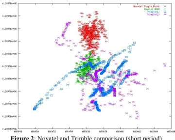
Figure 2 shows the positions given by both devices with the antennas fixed on the same place during a period of ten minutes. Blue and violet points have been obtained from the Trimble receiver in differential mode. Green and red points have been obtained from the Novatel receiver: the red ones are in single-point mode, while green ones were obtained in WAAS mode. At first sight, it can be noticed that points obtained from the Novatel receiver are less dispersed than Trimble ones. This is because differential GPS mode produces those kinds of points while in static mode. The Novatel receiver produces clouds of points more condensed in both modes, single-point and WAAS correction. Moreover, when using the WAAS correction mode points are less dispersed than in single-point mode.
Figure 2: Novatel and Trimble comparison (short period). The following tables (Table 1, 2, 3 and 4) show the main features of every mass of points (points are in UTM coordinates): Northing Easting Min 4209759,639 660455,0942 Max 4209763,319 660458,4115 Average 4209761,56 660456,5704 Std. Dev. 0,657573329 0,655565597
Table 1: Novatel in single-point mode.
Northing Easting
Min 4209757,042 660454,4374
Max 4209760,17 660457,6246
Average 4209758,876 660456,1395
Std. Dev. 0,533060064 0,644732281
Northing Easting
Min 4209755,442 660449,8872
Max 4209760,872 660461,6556
Average 4209757,732 660457,4924
Std. Dev. 1,225212923 2,191851115
Table 3: Trimble in differential mode (first time).
Northing Easting
Min 4209754,829 660452,4764
Max 4209762,5 660465,2473
Average 4209758,063 660457,8538
Std. Dev. 1,441776826 2,268107896
Table 4: Trimble in differential mode (second time). As can be noticed, points obtained with the Novatel receiver are closer than with Trimble, and their standard deviation is also lower.
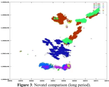
Figure 3: Novatel comparison (long period).
Figure 3 shows a different test, in this case using the Novatel receiver only. The receiver was obtaining points during 2 hours and 20 minutes fixed on the same place. Dark blue points are points obtained from WAAS/EGNOS mode. The other clusters of points are obtained from single-point mode. These clusters are coloured depending on the number of the satellites that were available to compute the position. It can be noticed that the change in the number of available satellites causes a change in the position of the centre of the cluster. However, the WAAS cluster is not clearly influenced by changes in the number of satellites, being centred in the same point.
Figure 4: Novatel comparison (different days).
In Figure 4 the data represented in Figure 3 is superimposed with new data, which was obtained during 3 hours and 14 minutes in WAAS mode, with the receiver in exactly the same point but a day after. It can be noticed that the red set of points (date 02-28-2001) are more dispersed than the green one (02-27-2001). This is due to new points were collected during a longer period of time, and thus the set tends to expand because there are more outliers. Moreover, between the centroid of the red cluster and the green cluster there is an offset. This offset is produced because the changes in conditions between the two different days. If we consider (4209669.19, 660567.39) as the real UTM coordinates of the point where the receiver was located on, we obtain the next results (Table 5). The reference coordinates were obtained with the Novatel receiver, averaging positions during 10 hours and obtaining an estimated accuracy of less than 1 meter.
Northing Easting Distance to
Real Point 02-27-2001 (Single-Point) 4209677,610 712000 660566,8381 91000 8,43415 02-27-2001 (WAAS) 4209671,165 581200 660564,8634 64000 3,52786 02-28-2001 (WAAS) 4209677,016 331000 660565,7041 53000 7,9972 Offset between WAAS sets 5,910840145
Table 5: The EGNOS System Test Bed. COMPARISONS IN DYNAMIC MODE
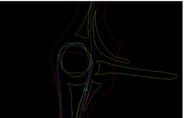
Figure 5 shows the comparison between the paths given by both devices. The magenta path was obtained from the Trimble receiver in differential mode. The green path was obtained from the Novatel receiver in single-point mode and the blue one was obtained from the Novatel receiver in WAAS mode. As can be noticed the Novatel paths have more
accuracy if we use the map (yellow and red lines) as a reference. In fact, in a given instant (light blue and light magenta lines) the vehicle was stopped and, while the differential GPS accumulated a certain amount of errors, the WAAS path presents no important errors.
Figure 5: Novatel and Trimble comparison (in a roundabout). Figure 6 shows another comparison between both receivers. As in the previous case, the magenta path was obtained from the Trimble receiver in differential mode, the green path was obtained from the Novatel receiver in single-point mode and the blue one was obtained from the Novatel receiver in WAAS mode. As can be noticed, when the Novatel system is using WAAS correction, both paths (Novatel-light blue and Trimble-dark magenta) are closer than when Novatel is using single-point calculations (Novatel-green and Trimble-light magenta). Moreover, the figure also shows a problem that appears when the receivers make use of differential correction (WAAS in Novatel or differential in Trimble) the vehicle is stopped. In this case, we obtain a mass of points that do not have the same value, because of the errors of the GPS estimate. Thus it seems like if the receivers were moving around a central point (this effect can be noticed at the end of the green and light magenta lines).
Figure 6: Novatel and Trimble comparison (in a road).
CONCLUSIONS
This paper presents some comparisons between a differentially corrected GPS receiver and an EGNOS receiver. Although this is still a preliminary work, some conclusions can be depicted. In the one hand, when the WAAS correction is active in static tests, the dispersion of data points is smaller (the standard deviation is smaller). This result is better than that obtained with the differentially corrected GPS, in which case data points vary more around the real position. Moreover, the average positioning error in WAAS mode is also smaller. On the other hand, in dynamic tests the WAAS corrected positions behave better than differentially corrected GPS (more stable). It is worth noting that EGNOS signal reception was lost in some places during the tests, and the receiver takes ten minutes to produce WAAS corrected points after the EGNOS signal is recovered. We have not gone deep into the causes of EGNOS signal lost, and this is a subject that deserves further study.
ACKNOWLEDGEMENTS
This work has been supported by Ministerio de Transportes project MIMICS and Ministerio de Ciencia y Tecnología PROFIT project FIT-160200-2000-33.
REFERENCES
[1] Hotchkiss, Noel J., A Comprehensive Guide to Land Navigation with GPS, Alexis Publications, 1999
[2] Kaplan, Elliot D., Understanding GPS: Principles and Application, Artech House Telecommunications Library, Artech House Publishers, 1996
[3] Corbasí Ortín, A., Sistemas de navegación: desde el compás magnético a la navegación por satélite, McGraw Hill, 1998
[4] Bernhardsen, T., Geographic Information System, an introduction (Second Edition), John Wiley & Sons Inc., 1999. [5] GPSCard MiLLeniumTM Command Descriptions Manual,
Version 4.501 Revision 1, Novatel Inc., 1999
[6] ACE III GPSTM System Designer Reference Manual,
[7] ESA EGNOS System Test Bed.
http://www.esa.int/navigation/pages/indexEST.htm
[8] Novatel Millennium.
http://www.novatel.ca/Products/Product_Overview/waas.html
[9] Trimble ACE III.