4655 Great America Parkway Santa Clara, CA 95054 Phone 1-800-4Nortel
http://www.nortelnetworks.com
Alteon OS 22.0.2
Command Reference
2
315393-J, January 2005 Copyright 2005 Nortel Networks, Inc., 4655 Great America Parkway, Santa Clara, California 95054, USA.
All rights reserved. Part Number: 315393-J.
This document is protected by copyright and distributed under licenses restricting its use, copying, distribution, and decompilation. No part of this document may be reproduced in any form by any means without prior written authorization of Nortel Networks, Inc. Documentation is provided “as is” without warranty of any kind, either express or implied, including any kind of implied or express warranty of non-infringement or the implied warranties of merchantability or fitness for a particular purpose.
U.S. Government End Users: This document is provided with a “commercial item” as defined by FAR 2.101 (Oct 1995) and contains “commercial technical data” and “commercial software documentation” as those terms are used in FAR 12.211-12.212 (Oct 1995). Government End Users are authorized to use this documentation only in accordance with those rights and restrictions set forth herein, consistent with FAR 12.211- 12.212 (Oct 1995), DFARS 227.7202 (JUN 1995) and DFARS 252.227-7015 (Nov 1995). Nortel Networks, Inc. reserves the right to change any products described herein at any time, and without notice. Nortel Networks, Inc. assumes no responsibility or liability arising from the use of products described herein, except as expressly agreed to in writing by Nortel Networks, Inc. The use and purchase of this product does not convey a license under any patent rights, trademark rights, or any other intellectual property rights of Nortel Networks, Inc.
Alteon OS, Alteon 2424, Alteon 2424-SSL, Alteon 2224, 2216, 2208, 3408, Alteon 180, Alteon 180e, Alteon 184, Alteon AD3, Alteon AD4, and ACEswitch are trademarks of Nortel Networks, Inc. in the United States and certain other countries. Cisco® and EtherChannel® are registered trademarks of Cisco Systems, Inc. in the United States and certain other countries. Check Point® and FireWall-1® are trademarks or registered trademarks of Check Point Software Technologies Ltd. Any other trademarks appearing in this manual are owned by their respective companies.
315393-J, January 2005 3
Contents
Preface 15
Who Should Use This Book 15
How This Book Is Organized 15
Related Documentation 16
Typographic Conventions 17
How to Get Help 18
Chapter 1: The Command Line Interface 19
Connecting to the Switch 20
Establishing a Console Connection 20
Requirements 20
Procedure 20
Establishing a Telnet Connection 21
Using a BOOTP Server 21
Running Telnet 21
Establishing an SSH Connection 22
Running SSH 22
Accessing the Switch 23
CLI Versus Setup 25
Command Line History and Editing 25
Idle Timeout 25
Chapter 2: First-Time Configuration 27
Using the Setup Utility 27
Information Needed For Setup 27
Starting Setup When You Log In 28
Stopping and Restarting Setup Manually 29
Stopping Setup 29
Restarting Setup 29
4 Contents
315393-J, January 2005
Setup Part 2: Port Configuration 31
Setup Part 3: VLANs 34
Setup Part 4: IP Configuration 35
IP Interfaces 35
Default Gateways 36
IP Routing 37
Setup Part 5: Final Steps 38
Optional Setup for SNMP Support 39
Optional Setup for Telnet Support 39
Setting Passwords 40
Changing the Default Administrator Password 40
Changing the Default User Password 42
Changing the Default Layer 4 Administrator Password 44
Chapter 3: Menu Basics 47
The Main Menu 47
Menu Summary 48
Global Commands 49
Command Line History and Editing 51
Command Line Interface Shortcuts 52
Command Stacking 52
Command Abbreviation 52
Tab Completion 52
Chapter 4: The Information Menu 53
Information Menu 53
System Information Menu 55
SNMPv3 System Information Menu 57
SNMPv3 USM User Table Information 58
SNMPv3 View Table Information 59
SNMPv3 Access Table Information 60
SNMPv3 Group Table Information 61
SNMPv3 Community Table Information 61
SNMPv3 Target Address Table Information 62
SNMPv3 Target Parameters Table Information 63
SNMPv3 Notify Table Information 64
SNMPv3 Dump Information 65
General System Information 66
Alteon OS 22.0.2 Command Reference
Contents 5 315393-J, January 2005
Show Last 30 Syslog Messages 67
Saved Syslog Messages 68
Management Port Information 69
SONMP Information 70
System Capacity Information 71
System Information Dump
74
Layer 2 Information Menu 77
Layer 2 FDB Information 78
Show All FDB Information 79
Clearing Entries from the Forwarding Database 80
Link Aggregation Control Protocol Information Menu 80
LACP Aggregator Information 81
LACP Port Information 82
LACP Dump Information 84
Layer 2 Spanning Tree Group Information 85
Trunk Group Information 87
VLAN Information 88
Layer2 Dump Information 89
Layer3 Information Menu 90
IP Routing Information 91
Show All IP Route Information 92
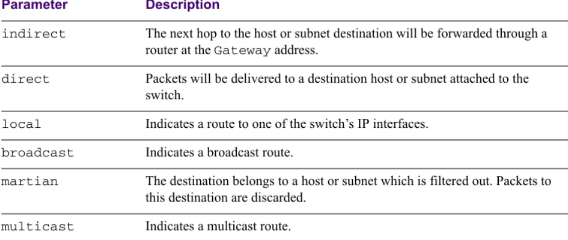
Type Parameters 92
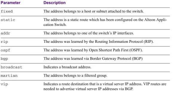
Tag Parameters 93
ARP Information Menu 93
Show ARP Entries on Referenced SP 95
Show All ARP Entry Information 95
ARP Address List Information 96
BGP Information Menu 96
BGP Peer information 97
BGP Summary information 97
Dump BGP Information 98
OSPF Information Menu 98
OSPF General Information 100
OSPF Interface Information 100
OSPF Database Information 101
OSPF Information Route Codes 102
OSPF Dump Information 103
6 Contents
315393-J, January 2005
VRRP Information 105
Layer3 Dump Information 107
Layer 4 Information Menu 110
Session Table Information 112
Samples of Session Dumps for Different Applications 113
Session dump information in Alteon OS 115
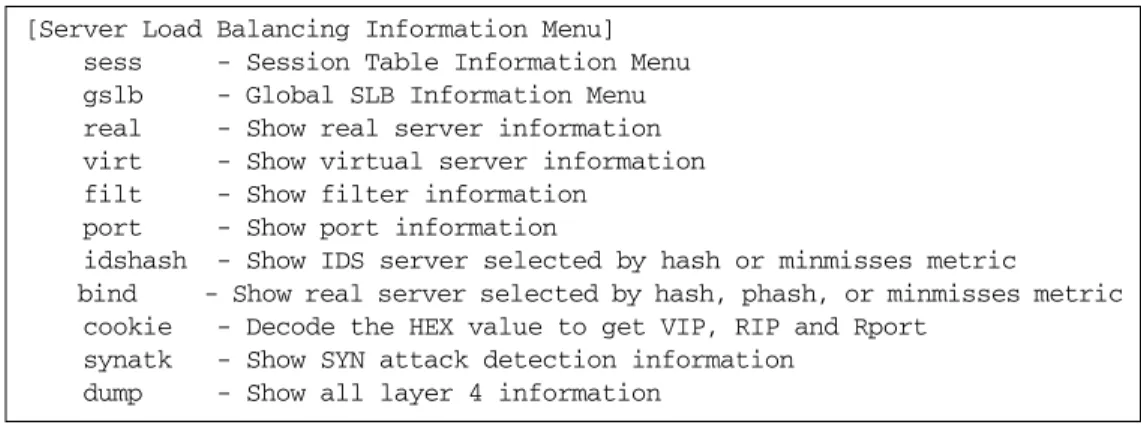
Global SLB Information Menu 117
Show All Layer 4 Information 118
Link Status Information 119
Port Information 120
Bandwidth Management Information 121
BWM IP User Information Menu 122
BWM Contract Information 124
Security Information 126
Software Enabled Keys 127
Information Dump 127
Chapter 5: The Statistics Menu 129
Statistics Menu 129
Port Statistics Menu 131
Bridging Statistics 132
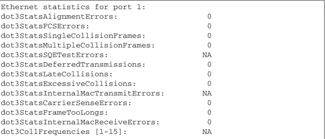
Ethernet Statistics 133
Interface Statistics 136
Interface Protocol Statistics 138
Link Statistics 139
RMON Statistics 140
Port Dump Statistics 143
Layer 2 Statistics Menu 144
FDB Statistics 145
LACP Statistics 146
Spanning Tree Group Statistics 147
Layer 3 Statistics Menu 148
OSPF Statistics Menu 150
OSPF Global Statistics 151
IP Statistics 155
Route Statistics 157
ARP statistics 159
VRRP Statistics 159
Alteon OS 22.0.2 Command Reference
Contents 7 315393-J, January 2005
DNS Statistics 160
ICMP Statistics 161
Interface Statistics 163
TCP Statistics 165
UDP Statistics 167
Server Load Balancing Statistics Menu 167
Server Load Balancing SP statistics Menu 170
SP Real Server Statistics 170
SP Filter Statistics 171
SP Maintenance Statistics 172
Global SLB Statistics Menu 174
Real Server Global SLB Statistics 175
Virtual Server Global SLB Statistics 175
Global SLB Site Statistics 176
Global SLB Maintenance Statistics 177
Real Server SLB Statistics 179
Per Service Octet Counters 179
Real Server Group Statistics 180
Virtual Server SLB Statistics 181
Filter SLB Statistics 181
SLB Layer7 Statistics Menu 182
Layer7 Redirection Statistics 182
Layer 7 SLB String Statistics 183
Layer 7 SLB Maintenance Statistics 184
SLB Secure Socket Layer Statistics 186
File Transfer Protocol SLB and Filter Statistics Menu 187
Active FTP SLB Parsing and Filter Statistics 188
Passive FTP SLB Parsing Statistics 188
FTP SLB Maintenance Statistics 189
FTP SLB Statistics Dump 189
RTSP SLB Statistics 190
DNS SLB Statistics 191
WAP SLB Statistics 192
SLB Maintenance Statistics 194
SIP SLB Statistics 196
Clearing the SLB Statistics 196
BWM Statistics Menu 198
8 Contents
315393-J, January 2005
BWM Switch Processor Contract Statistics Menu 199
BWM Switch Processor Rate Contract Statistics 199
BWM Contract Statistics 200
BWM Contract Rate Statistics 201
BWM History Statistics 203
BWM Maintenance Statistics 204
BWM IP Users Statistics 204
Management Processor Statistics 205
MP Packet Statistics 206
TCP Statistics 208
UCB Statistics 208
MP-Specific SFD Statistics 209
CPU Statistics 209
SP Specific Statistics 210
SP-Specific Maintenance Statistics 211
CPU Statistics 211
Security Statistics 212
DOS Attack Statistics Menu 213
Types of DOS Attacks 214
IP Access Control List Statistics 214
UDP Blast Statistics 215
UDP Blast Dump Statistics 215
UDP Pattern Match Statistics 216
Rate Limiting Statistics 216
Dump Statistics for Security 217
SNMP Statistics 218
NTP Statistics 222
Port Mirroring Statistics Menu 224
Management Port Statistics 224
Dump Statistics 225
Chapter 6: The Configuration Menu 227
Configuration Menu 227
Viewing, Applying, and Saving Changes 228
Viewing Pending Changes 229
Applying Pending Changes 229
Saving the Configuration 229
System Configuration 231
Alteon OS 22.0.2 Command Reference
Contents 9 315393-J, January 2005
System Host Log Configuration 233
Seven Levels of Severity 234
Management Port Configuration Menu 234
Management Port Link Menu 237
SSH Server Configuration Menu 237
RADIUS Server Configuration 239
TACACS+ Server Configuration Menu 240
NTP Server Configuration 242
SynOptics Network Management Protocol Configuration 243
System SNMP Configuration 244
SNMPv3 Configuration Menu 247
User Security Model Configuration Menu 249
SNMPv3 View Configuration Menu 250
View-based Access Control Model Configuration Menu 251
SNMPv3 Group Configuration Menu 253
SNMPv3 Community Table Configuration Menu 254
SNMPv3 Target Address Table Configuration Menu 255
SNMPv3 Target Parameters Table Configuration Menu 256
SNMPv3 Notify Table Configuration Menu 257
System Health Check Configuration Menu 258
System Access Control Configuration 259
Management Networks Menu 260
User Access Control Menu 261
HTTPS Access Configuration Menu 263
System User ID Configuration Menu 264
Port Configuration 265
Alteon OS 2000 Series 265
Fast Ethernet Ports 265
SFP GBIC Ports 265
Port Link Configuration 267
Alteon OS 3000 Series 269
Port Configuration on Alteon OS 3408 269
Single-Mode ports 270
Single-Mode Copper Port Gigabit Ethernet Link Configuration Menu 271
Single-Mode SFP Gigabit Ethernet Port Link Configuration Menu 273
Dual-Mode Ports 274
Dual-Mode Copper Port Link Configuration 276
Dual-Mode SFP Gigabit Link Configuration Menu 277
10 Contents
315393-J, January 2005
Temporarily Disabling a Port 277
Port Mirroring Menu 278
Port-Mirroring Menu 278
Bandwidth Management Configuration 279
Bandwidth Management Contract Configuration 281
BWM Contract Time Policy Configuration Menu 283
Bandwidth Management Policy Configuration 284
Bandwidth Management Group Configuration Menu 285
Bandwidth Management Current Configuration 286
Layer 2 Configuration Menu 287
Spanning Tree Group Configuration 288
Bridge Spanning Tree Configuration 290
Spanning Tree Port Configuration 291
Trunk Configuration 292
Link Aggregation Control Protocol Menu 294
LACP Port Configuration Menu 296
VLAN Configuration 297
Layer 3 Configuration Menu 299
IP Interface Configuration 301
Default IP Gateway Configuration 302
Default Gateway Metrics 303
IP Static Route Configuration 304
ARP Configuration Menu 304
ARP Static Configuration Menu 305
IP Forwarding Configuration Menu 306
Local Network Route Caching Definition 306
Defining IP Address Ranges for the Local Route Cache 307
Network Filter Configuration 308
Route Map Configuration Menu 309
IP Access List Configuration Menu 311
Autonomous System Filter Path 312
Routing Information Protocol Configuration 313
Open Shortest Path First Configuration 315
Area Index Configuration Menu 317
OSPF Summary Range Configuration Menu 318
OSPF Interface Configuration Menu 319
OSPF Virtual Link Configuration Menu 321
OSPF Host Entry Configuration Menu 322
Alteon OS 22.0.2 Command Reference
Contents 11 315393-J, January 2005
OSPF Route Redistribution Configuration Menu. 323
OSPF MD5 Key Configuration Menu 324
Border Gateway Protocol Configuration 324
BGP Peer Configuration Menu 326
BGP Redistribution Configuration Menu 328
BGP Aggregate Routing Configuration Menu 329
IP Forwarding Port Configuration Menu 330
Domain Name System Configuration Menu 331
Bootstrap Protocol Relay Configuration Menu 332
VRRP Configuration Menu 333
Virtual Router Configuration Menu 334
Virtual Router Priority Tracking Configuration 336
Virtual Router Group Menu 338
Virtual Router Group Priority Tracking Configuration Menu 340
Virtual Router Group Configuration 341
Virtual Router Group Priority Tracking Configuration 343
VRRP Interface Configuration 345
VRRP Tracking Configuration 346
Default Gateway Metrics 347
Security Configuration Menu 348
IP Address Access Control List Configuration Menu 349
Pattern Matching Menu 350
Port Security Configuration Menu 351
UDP Blast Protection Configuration Menu 352
Setup 353
Dump 353
Saving the Active Switch Configuration 354
Restoring the Active Switch Configuration 354
Chapter 7: The SLB Configuration Menu 355
SLB Configuration 356
Filtering and Layer 4 (Server Load Balancing) 358
Real Server SLB Configuration 358
Real Server Layer 7 Configuration 362
Real server IDS Configuration Menu 363
Real Server Group SLB Configuration 364
SLB Health Check Types 367
Server Load Balancing Metrics 370
12 Contents
315393-J, January 2005
Virtual Server SLB Configuration 372
Virtual Server Service Configuration 375
Virtual Server RTSP Configuration 380
Cookie-Based Persistence 381
SLB Filter Configuration 383
Defining IP Address Ranges for Filters 387
Advanced Filter Configuration 388
802.1p Advanced Menu 391
Advanced Filter TCP Configuration 392
IP Advanced Menu 393
ICMP Message Types 394
Layer 7 Advanced Filter Configuration Menu 395
SLB Filter Advanced Security Menu 397
Advanced Security Rate Limiting Configuration Menu 398
Port SLB Configuration 399
Global SLB Configuration 401
GSLB Remote Site Configuration 403
GSLB Network Preference Configuration Menu 405
GSLB Rule Configuration Menu 406
Global SLB Rule Metric Menu 408
Layer 7 SLB Resource Definition Menu 408
Web Cache Redirection Configuration 409
Server Load Balance Resource Configuration Menu 411
WAP Configuration 412
Synchronize Peer Switch Configuration 413
Peer Switch Configuration 414
Advanced Layer 4 Configuration 415
SYN Attack Detection Configuration Menu 418
Advanced SMT Real Server Port Configuration Menu 418
Inbound Link Load Balancing configuration Menu 419
Inbound Link Load Balancing Domain Record Menu 420
Inbound Link Load Balancing Mapping Menu 421
Advanced Health Check Configuration Menu 421
Scriptable Health Checks Configuration 423
SNMP Health Check Configuration 425
WAP Health Check Configuration 426
WSP Content Health Check 428
Alteon OS 22.0.2 Command Reference
Contents 13 315393-J, January 2005
Proxy IP Address Configuration Menu 430
SLB Peer Proxy IP Address Menu 431
Chapter 8: The Operations Menu 433
Operations Menu 433
Operations-Level Port Options 435
Operations-Level SLB Options 436
Real Server Group Operations 437
Global SLB Operations Menu 438
Operations-Level VRRP Options. 439
Operations-Level Bandwidth Management Options 439
Operations-Level IP Options 440
Operations-Level BGP Options 440
Activating Optional Software 441
Removing Optional Software 442
Chapter 9: The Boot Options Menu 443
Boot Menu 443
Scheduled Reboot of the Switch 444
Scheduled Reboot Menu 444
Updating the Switch Software Image 444
Downloading New Software to Your Switch 444
Selecting a Software Image to Run 446
Uploading a Software Image from Your Switch 446
Selecting a Configuration Block 447
Resetting the Switch 448
Chapter 10: The Maintenance Menu 449
Maintenance Menu 449
System Maintenance Options 451
Forwarding Database Options 451
ARP Cache Options 452
ARP Entries on a Single Port 453
IP Route Manipulation 454
Debugging Options 455
Uuencode Flash Dump 456
TFTP System Dump Put 456
Clearing Dump Information 457
Panic Command 457
14 Contents
315393-J, January 2005
Unscheduled System Dumps 458
Appendix A: Alteon OS Syslog Messages 459
LOG_WARNING 459
LOG_ALERT 460
LOG_CRIT 461
LOG_ERR 461
LOG_NOTICE 467
LOG_INFO 469
Appendix B: Alteon OS SNMP Agent 471
Appendix C: Performing a Serial Download 475
Glossary 477
315393-J, January 2005 15
Preface
The Alteon OS 22.0.2 Command Reference describes how to configure and use the Alteon OS software with your Alteon OS.
For documentation on installing the switches physically, see the Hardware Installation Guide
for your particular switch model.
Who Should Use This Book
This Command Reference is intended for network installers and system administrators engaged in configuring and maintaining a network. The administrator should be familiar with Ethernet concepts, IP addressing, the IEEE 802.1d Spanning Tree Protocol, and SNMP configuration parameters.
How This Book Is Organized
“The Command Line Interface,” describes how to connect to the switch and access the infor-mation and configuration menus.
“First-Time Configuration,” describes how to use the Setup utility for initial switch configu-ration and how to change the system passwords.
“Menu Basics,” provides an overview of the menu system, including a menu map, global commands, and menu shortcuts.
“The Information Menu,” shows how to view switch configuration parameters.
“The Statistics Menu,” shows how to view switch performance statistics.
“The Configuration Menu,” shows how to configure switch system parameters, ports, VLANs, Spanning Tree Protocol, SNMP, Port Mirroring, IP Routing, Port Trunking, and more.
16 Preface
315393-J, January 2005 “The SLB Configuration Menu,” shows how to configure Server Load Balancing, Filtering, Global Server Load Balancing, and more.
“The Operations Menu,” shows how to use commands which affect switch performance immediately, but do not alter permanent switch configurations (such as temporarily disabling ports). The menu describes how to activate or deactivate optional software features.
“The Boot Options Menu,” describes the use of the primary and alternate switch images, how to load a new software image, and how to reset the software to factory defaults.
“The Maintenance Menu,” shows how to generate and access a dump of critical switch state information, how to clear it, and how to clear part or all of the forwarding database.
Appendix A, “Alteon OS Syslog Messages,” shows a listing of syslog messages.
Appendix B, “Alteon OS SNMP Agent,” lists the Management Interface Bases (MIBs) sup-ported in the switch software.
Appendix C, “Performing a Serial Download,” shows how to directly load a binary software image into the switch for upgrade or maintenance.
“Glossary” defines the terminology used throughout the book.
“Index” includes pointers to the description of the key words used throughout the book.
Related Documentation
Alteon OS 22.0.2 Application Guide (Part No. 315394-H)
Provides application explanations and configuration examples for the Switch.
Alteon OS Browser-Based Interface (BBI) Quick Guide (315395-C)
Provides a description of the Switch BBI and how to configure and access it on the Switch.
Alteon Application Switch Hardware Installation Guide (315396-E)
Provides a description of the Alteon Application Switch hardware, the physical features, how to install it, and how to troubleshoot it.
Alteon OS 22.0.2 Release Notes (315397-H).
This document provides a description of new features and caveats and limitations, if any, in the software.
Alteon OS 22.0.2 Command Reference
Preface 17 315393-J, January 2005
Typographic Conventions
The following table describes the typographic styles used in this book.
Table 1 Typographic Conventions
Typeface or Symbol
Meaning Example
AaBbCc123 This type is used for names of commands, files, and directories used within the text.
View the readme.txt file. It also depicts on-screen computer output and
prompts.
Main# AaBbCc123 This bold type appears in command
exam-ples. It shows text that must be typed in exactly as shown.
Main# sys
<AaBbCc123> This italicized type appears in command examples as a parameter placeholder. Replace the indicated text with the appropriate real name or value when using the command. Do not type the brackets.
To establish a Telnet session, enter: host# telnet <IP address>
This also shows book titles, special terms, or words to be emphasized.
Read your User’s Guide thoroughly. [ ] Command items shown inside brackets are
optional and can be used or excluded as the situation demands. Do not type the brackets.
18 Preface
315393-J, January 2005
How to Get Help
If you purchased a service contract for your Nortel Networks product from a distributor or autho-rized reseller, contact the technical support staff for that distributor or reseller for assistance. If you purchased a Nortel Networks service program, contact one of the following Nortel Net-works Technical Solutions Centers:
Additional information about the Nortel Networks Technical Solutions Centers is available at the following URL:
http://www.nortelnetworks.com/help/contact/global
An Express Routing Code (ERC) is available for many Nortel Networks products and services. When you use an ERC, your call is routed to a technical support person who specializes in sup-porting that product or service. To locate an ERC for your product or service, refer to the fol-lowing URL:
http://www.nortelnetworks.com/help/contact/erc/index.html Technical Solutions Center Telephone
Europe, Middle East, and Africa 00800 8008 9009 or
+44 (0) 870 907 9009
North America (800) 4NORTEL or (800) 466-7835 Asia Pacific (61) (2) 8870-8800
315393-J, January 2005 19
C
HAPTER
1
The Command Line Interface
Your Alteon Application Switch is ready to perform basic switching functions right out of the box. Some of the more advanced features, however, require some administrative configuration before they can be used effectively.
The extensive Alteon OS switching software included in your switch provides a variety of options for accessing and configuring the switch:
A built-in, text-based command line interface and menu system for access via local termi-nal or remote Telnet session
A GUI-based Element Management System (EMS) for interactive network access
SNMP support for access through network management software such as HP OpenView
Alteon OS Browser-Based Interface (BBI)
The command line interface is the most direct method for collecting switch information and performing switch configuration. Using a basic terminal, you are presented with a hierarchy of menus that enable you to view information and statistics about the switch, and to perform any necessary configuration.
20 Chapter 1: The Command Line Interface
315393-J, January 2005
Connecting to the Switch
You can access the command line interface in any one of the following ways:
Using a console connection via the console port
Using a Telnet connection over the network
Using an SSH connection to securely log into another computer over a network
Establishing a Console Connection
Requirements
To establish a console connection with the switch, you will need the following:
An ASCII terminal or a computer running terminal emulation software set to the parame-ters shown in the table below:
A standard serial cable with a male DB9 connector (see your switch hardware installation guide for specifics).
Procedure
1. Connect the terminal to the Console port using the serial cable.
2. Power on the terminal.
3. To establish the connection, press <Enter> a few times on your terminal.
You will next be required to enter a password for access to the switch. (For more information, see “Setting Passwords” on page 40).
Table 1-1 Console Configuration Parameters
Parameter Value
Baud Rate Data Bits Parity Stop Bits Flow Control
9600 8 None 1 None
Alteon OS 22.0.2 Command Reference
Chapter 1: The Command Line Interface 21 315393-J, January 2005
Establishing a Telnet Connection
A Telnet connection offers the convenience of accessing the switch from any workstation con-nected to the network. Telnet access provides the same options for user access and administra-tor access as those available through the console port.
To configure the switch for Telnet access, you need to have a device with Telnet software located on the same network as the switch. The switch must have an IP address. The switch can get its IP address in one of two ways:
Dynamically, from a BOOTP server on your network
Manually, when you configure the switch IP address (see “Setup Part 1: Basic System Configuration” on page 29).
NOTE – You need to enable Telnet and SSH, using serial connection, before you can use these
methods of accessing the switch. Refer to “Establishing a Telnet Connection” on page 21.
Using a BOOTP Server
By default, the Alteon OS software is set up to request its IP address from a BOOTP server. If you have a BOOTP server on your network, add the MAC address of the switch to the BOOTP configuration file located on the BOOTP server. The MAC address can be found on a small white label on the back panel of the switch. The MAC address can also be found in the System Information menu (see “System Information” on page 55).
NOTE – If connecting to the management port, BOOTP is not supported. The port must be
manually configured with the proper IP address.
Running Telnet
Once the IP parameters on the Alteon Application Switch are configured, you can access the CLI using a Telnet connection. To establish a Telnet connection with the switch, run the Telnet pro-gram on your workstation and issue the Telnet command, followed by the switch IP address:
You will then be prompted to enter a password as explained on page 22.
22 Chapter 1: The Command Line Interface
315393-J, January 2005
Establishing an SSH Connection
Although a remote network administrator can manage the configuration of an Alteon Applica-tion Switch via Telnet, this method does not provide a secure connection. The SSH (Secure Shell) protocol enables you to securely log into another computer over a network to execute commands remotely. As a secure alternative to using Telnet to manage switch configuration, SSH ensures that all data sent over the network is encrypted and secure.
The switch can do only one session of key/cipher generation at a time. Thus, a SSH/SCP client will not be able to login if the switch is doing key generation at that time or if another client has just logged in before this client. Similarly, the system will fail to do the key generation if a SSH/SCP client is logging in at that time.
The supported SSH encryption and authentication methods are listed below.
Server Host Authentication: Client RSA-authenticates the switch in the beginning of every connection.
Key Exchange: RSA
Encryption: 3DES-CBC, DES
User Authentication: Local password authentication, Radius The following SSH clients have been tested:
SSH 1.2.23 and SSH 1.2.27 for Linux (freeware)
SecureCRT 3.0.2 and SecureCRT 3.0.3 (Van Dyke Technologies, Inc.)
F-Secure SSH 1.1 for Windows (Data Fellows)
NOTE – The Alteon OS implementation of SSH is based on SSH version 1.5 and supports
SSH-1.5-1.X.XX. SSH clients of other versions (especially Version 2) will not be supported.
Running SSH
Once the IP parameters are configured and the SSH service is turned on the Alteon Application Switch, you can access the command line interface using an SSH connection.
To establish an SSH connection with the switch, run the SSH program on your workstation by issuing the SSH command, followed by the switch IP address:
Alteon OS 22.0.2 Command Reference
Chapter 1: The Command Line Interface 23 315393-J, January 2005
or, if SecurID authentication is required, use the following command:
You will then be prompted to enter your user name and password.
Accessing the Switch
To enable better switch management and user accountability, seven levels or classes of user access have been implemented on the Alteon Application Switch. Levels of access to CLI, Web management functions, and screens increase as needed to perform various switch management tasks. Conceptually, access classes are defined as follows:
User interaction with the switch is completely passive—nothing can be changed on the
Alteon Application Switch. Users may display information that has no security or privacy implications, such as switch statistics and current operational state information.
Operators can only effect temporary changes on the Alteon Application Switch. These changes will be lost when the switch is rebooted/reset. Operators have access to the switch management features used for daily switch operations. Because any changes an operator makes are undone by a reset of the switch, operators cannot severely impact switch opera-tion.
Administrators are the only ones that may make permanent changes to the switch configu-ration—changes that are persistent across a reboot/reset of the switch. Administrators can access switch functions to configure and troubleshoot problems on the Alteon Application Switch. Because administrators can also make temporary (operator-level) changes as well, they must be aware of the interactions between temporary and permanent changes. Access to switch functions is controlled through the use of unique surnames and passwords. Once you are connected to the switch via local console, Telnet, or SSH, you are prompted to enter a password. The default user names/password for each access level are listed in the fol-lowing table.
NOTE – It is recommended that you change default switch passwords after initial configuration
and as regularly as required under your network security policies. For more information, see
“Setting Passwords” on page 40.
24 Chapter 1: The Command Line Interface
315393-J, January 2005
NOTE – With the exception of the “admin” user, access to each user level can be disabled by setting the password to an empty value. All user levels below “admin” will by default be ini-tially disabled (empty password) until they are enabled by the “admin” user. This prevents inadvertently leaving the switch open to unauthorized users.
Table 1-2 User Access Levels
User Account Description and Tasks Performed Password User The User has no direct responsibility for switch management.
He or she can view all switch status information and statistics, but cannot make any configuration changes to the switch.
user
SLB Operator The SLB Operator manages Web servers and other Internet ser-vices and their loads. In addition to being able to view all switch information and statistics, the SLB Operator can enable/disable servers using the Server Load Balancing operation menu.
slboper
Layer 4 Operator The Layer 4 Operator manages traffic on the lines leading to the shared Internet services. This user currently has the same access level as the SLB operator. and the access level is reserved for future use, to provide access to operational commands for opera-tors managing traffic on the line leading to the shared Internet services.
l4oper
Operator The Operator manages all functions of the switch. In addition to SLB Operator functions, the Operator can reset ports or the entire switch.
oper
SLB Administrator The SLB Administrator configures and manages Web servers and other Internet services and their loads. In addition to SLB Operator functions, the SLB Administrator can configure parameters on the Server Load Balancing menus, with the exception of not being able to configure filters or bandwidth management.
slbadmin
Layer 4 Administrator
The Layer 4 Administrator configures and manages traffic on the lines leading to the shared Internet services. In addition to SLB Administrator functions, the Layer 4 Administrator can configure all parameters on the Server Load Balancing menus, including filters and bandwidth management.
l4admin
Administrator The superuser Administrator has complete access to all menus, information, and configuration commands on the Alteon Appli-cation Switch, including the ability to change both the user and administrator passwords.
Alteon OS 22.0.2 Command Reference
Chapter 1: The Command Line Interface 25 315393-J, January 2005
CLI Versus Setup
Once the administrator password is verified, you are given complete access to the switch. If the switch is still set to its factory default configuration, the system will ask whether you wish to run Setup (see Chapter 2, “First-Time Configuration”), a utility designed to help you through the first-time configuration process. If the switch has already been configured, the Main Menu of the CLI is displayed instead.
The following table shows the Main Menu with administrator privileges.
NOTE – If you are accessing a user account or Layer 4 administrator account, some menu
options will not be available.
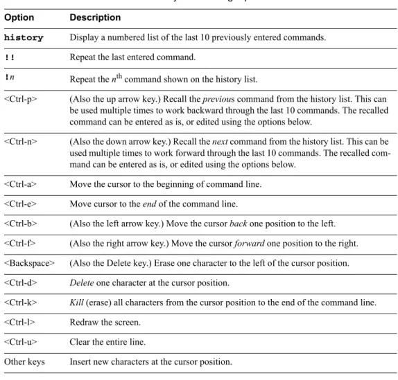
Command Line History and Editing
For a description of global commands, shortcuts, and command line editing functions, see “Menu Basics” on page 47.”
Idle Timeout
By default, the switch will disconnect your console or Telnet session after five minutes of inactiv-ity. This function is controlled by the idle timeout parameter, which can be set from 1 to 10080 minutes. For information on changing this parameter, see “System Configuration” on page 231.
[Main Menu]
info - Information Menu stats - Statistics Menu cfg - Configuration Menu oper - Operations Command Menu boot - Boot Options Menu maint - Maintenance Menu
diff - Show pending config changes [global command] apply - Apply pending config changes [global command] save - Save updated config to FLASH [global command] revert - Revert pending or applied changes [global command] exit - Exit [global command, always available]
26 Chapter 1: The Command Line Interface
315393-J, January 2005 27
C
HAPTER
2
First-Time Configuration
To help with the initial process of configuring your switch, the Alteon OS software includes a Setup utility. The Setup utility prompts you step-by-step to enter all the necessary information for basic configuration of the switch. This chapter describes how to use the Setup utility and how to change system passwords.
NOTE – If you are configuring a 2000-SSL Series Switch, you can use the Switch Setup Utility
in the Alteon OS 2000-SSL Series Quick Setup Guide (part number 215102-A) instead for set-ting up the Switch and the SSL Processor. Then return to this guide for configuration and man-agement information on your Switch.
Using the Setup Utility
Whenever you log in as the system administrator under the factory default configuration, you are asked whether you wish to run the Setup utility. Setup can also be activated manually from the command line interface any time after login.
Information Needed For Setup
Setup requests the following information:
Basic system information Date & time
Whether to use BOOTP or not
Whether to use Spanning Tree Protocol or not Management port configuration
Optional configuration for each port
Speed, duplex, flow control, and negotiation mode (as appropriate) Whether to use VLAN tagging or not (as appropriate)
28 Chapter 2: First-Time Configuration
315393-J, January 2005 Optional configuration for each VLAN
Name of VLAN
Which ports are included in the VLAN
Optional configuration of IP parameters
IP address, subnet mask, and broadcast address, and VLAN for each IP interface IP addresses for up to four default gateways
Destination, subnet mask, and gateway IP address for each IP static route Whether IP forwarding is enabled or not
Whether the RIP supply is enabled or not
Starting Setup When You Log In
The Setup prompt appears automatically whenever you login as the system administrator under the factory default settings.
1. Connect to the switch console.
After connecting, the login prompt will appear as shown below.
2. Enter admin as the default administrator password.
If the factory default configuration is detected, the system prompts:
NOTE – If the default admin login is unsuccessful, or if the administrator Main Menu appears
instead, the system configuration has probably been changed from the factory default settings. If you are certain that you need to return the switch to its factory default settings, see “Select-ing a Configuration Block” on page 447.
3. Enter y to begin the initial configuration of the switch, or n to bypass the Setup facility. Enter Password:
Connected to Alteon Application Switch 2424 18:44:05 Mon April 12, 2004
The switch is booted with factory default configuration.
To ease the configuration of the switch, a "Set Up" facility which will prompt you with those configuration items that are essential to the operation of the switch is provided.
Alteon OS 22.0.2 Command Reference
Chapter 2: First-Time Configuration 29 315393-J, January 2005
Stopping and Restarting Setup Manually
Stopping Setup
To abort the Setup utility, press <Ctrl-C> during any Setup question. When you abort Setup, the system will prompt:
Enter n to abort Setup, or y to restart the Setup program at the beginning.
Restarting Setup
You can restart the Setup utility manually at any time by entering the following command at the administrator prompt:
Setup Part 1: Basic System Configuration
When Setup is started, the system prompts:
1. Enter y if you will be configuring VLANs. Otherwise enter n.
If you decide not to configure VLANs during this session, you can configure them later using the configuration menus, or by restarting the Setup facility. For more information on configur-ing VLANs, see the Alteon OS 22.0.2 Application Guide.
Next, the Setup utility prompts you to input basic system information.
2. Enter the year of the current date at the prompt:
Enter the last two digits of the year as a number from 00 to 99. “00” is considered 2000. To keep the current year, press <Enter>.
Would you like to run from top again? [y/n]
# /cfg/setup
"Set Up" will walk you through the configuration of
System Date and Time, BOOTP, Spanning Tree, Management port, Port Speed/Mode,
VLANs, and IP interfaces. [type Ctrl-C to abort "Set Up"] ---Will you be configuring VLANs? [y/n]
System Date: Enter year [2004]:
30 Chapter 2: First-Time Configuration
315393-J, January 2005
3. Enter the month of the current system date at the prompt:
Enter the month as a number from 1 to 12. To keep the current month, press <Enter>.
4. Enter the day of the current date at the prompt:
Enter the date as a number from 1 to 31. To keep the current day, press <Enter>.
5. Enter the hour of the current system time at the prompt:
Enter the hour as a number from 00 to 23. To keep the current hour, press <Enter>.
6. Enter the minute of the current time at the prompt:
Enter the minute as a number from 00 to 59. To keep the current minute, press <Enter>.
7. Enter the seconds of the current time at the prompt:
Enter the seconds as a number from 00 to 59. To keep the current second, press <Enter>. The system displays the date and time settings:
8. Enable or disable the use of BOOTP at the prompt:
System Date: Enter month [4]:
Enter day [12]:
System Time:
Enter hour in 24-hour format [18]:
Enter minutes [55]:
Enter seconds [37]:
System clock set to 18:55:36 Mon April 12, 2004.
BootP Option:
Current BOOTP usage: disabled Enter new BOOTP usage [d/e]:
Alteon OS 22.0.2 Command Reference
Chapter 2: First-Time Configuration 31 315393-J, January 2005
If available on your network, a BOOTP server can supply the switch with IP parameters so that you do not have to enter them manually. BOOTP must be disabled however, before the system will prompt for IP parameters.
Enter d to disable the use of BOOTP, or enter e to enable the use of BOOTP. To keep the current
setting, press <Enter>.
9. Turn Spanning Tree Protocol on or off at the prompt:
Enter y to turn off Spanning Tree, or enter n to leave Spanning Tree on.
Setup Part 2: Port Configuration
NOTE – The port configuration options shown in these steps are for the Alteon OS 2424. When
configuring port options for other switches, some of the prompts and options may be different.
1. If desired, set up the management port:
If you answer y to configure the management port, you will be prompted for IP address, subnet mask, broadcast address, default gateway, and other management port options.
2. Select the port to configure, or skip port configuration at the prompt:
If you wish to change settings for individual ports, enter the number of the port you wish to configure. To skip port configuration, press <Enter> without specifying any port and go to “Setup Part 3: VLANs” on page 34.
Spanning Tree:
Current Spanning Tree setting: ON Turn Spanning Tree OFF? [y/n]
Management Port Config:
Configure management port? [y/n] y
Port Config:
32 Chapter 2: First-Time Configuration
315393-J, January 2005
3. If appropriate, configure Ethernet/Fast Ethernet port speed.
If you selected a port that has an Ethernet/Fast Ethernet connector, the system prompts:
Enter the port speed from the options available, or enter any to have the switch auto-sense the
port speed. To keep the current setting, press <Enter>.
4. If appropriate, configure Ethernet/Fast Ethernet port duplex mode.
If you selected a port that has an Ethernet/Fast Ethernet connector, the system prompts:
Enter full for full-duplex, half for half-duplex, or any to have the switch auto-negotiate. To
keep the current setting, press <Enter>.
5. If appropriate, configure Ethernet/Fast Ethernet port flow control.
If you selected a port that has an Ethernet/Fast Ethernet connector, the system prompts:
Enter rx to enable receive flow control, tx for transmit flow control, both to enable both, or
none to turn flow control off for the port. To keep the current setting, press <Enter>.
6. If appropriate, configure Ethernet/Fast Ethernet port autonegotiation mode. If you selected a port that has an Ethernet/Fast Ethernet connector, the system prompts:
Enter on to enable autonegotiation, off to disable it, or press <Enter> to keep the current setting.
Fast Link Configuration: Port Speed:
Current Port 1 speed setting: 10/100 Enter new speed ["10"/"100"/"any"]:
Port Mode:
Current port 1 mode setting: any Enter new speed ["full"/"half"/"any"]
Port Flow Control:
Current Port 1 flow control setting: both Enter new value ["rx"/"tx"/"both"/"none"]:
Port Auto Negotiation:
Current Port 1 autonegotiation: on Enter new value ["on"/"off"]:
Alteon OS 22.0.2 Command Reference
Chapter 2: First-Time Configuration 33 315393-J, January 2005
7. If appropriate, configure Gigabit Ethernet port flow parameters.
If you selected a port that has a Gigabit Ethernet connector, the system prompts:
Enter rx to enable receive flow control, tx for transmit flow control, both to enable both, or
none to turn flow control off for the port. To keep the current setting, press <Enter>.
8. If appropriate, configure Gigabit Ethernet port autonegotiation mode. If you selected a port that has a Gigabit Ethernet connector, the system prompts:
Enter on to enable port autonegotiation, off to disable it, or press <Enter> to keep the current setting.
9. If configuring VLANs, enable or disable VLAN tagging for the port. If you have selected to configure VLANs back in Part 1, the system prompts:
Enter d to disable VLAN tagging for the port or enter e to enable VLAN tagging for the port.
To keep the current setting, press <Enter>.
10. The system prompts you to configure the next port:
When you are through configuring ports, press <Enter> without specifying any port. Other-wise, repeat the steps in this section.
Gig Link Configuration: Port Flow Control:
Current Port 1 flow control setting: both Enter new value ["rx"/"tx"/"both"/"none"]:
Port Auto Negotiation:
Current Port 1 autonegotiation: on Enter new value ["on"/"off"]:
Port VLAN tagging config (tagged port can be a member of multiple VLANs) Current TAG flag: disabled
Enter new TAG status [d/e]:
34 Chapter 2: First-Time Configuration
315393-J, January 2005
Setup Part 3: VLANs
If you chose to skip VLANs configuration back in Part 1, skip to “Setup Part 4: IP Configura-tion” on page 35.
1. Select the VLAN to configure, or skip VLAN configuration at the prompt:
If you wish to change settings for individual VLANs, enter the number of the VLAN you wish to configure. To skip VLAN configuration, press <Enter> without typing a VLAN number and go to “Setup Part 4: IP Configuration” on page 35.
2. Enter the new VLAN name at the prompt:
Entering a new VLAN name is optional. To use the pending new VLAN name, press <Enter>.
3. Enter the VLAN port numbers.
The system prompts you to define the first port in the VLAN:
Type the first port number to add to the current VLAN and press <Enter>. The right angle prompt appears:
For each additional port in the VLAN, type the port number and press <Enter> to move to the next line. Repeat this until all ports for the VLAN being configured are entered. When you are finished adding ports to this VLAN, press <Enter> without specifying any port.
4. The system prompts you to configure the next VLAN:
VLAN Config:
Enter VLAN number from 2 to 4090, NULL at end:
VLAN is newly created.
Pending new VLAN name: "VLAN 2" Enter new VLAN name, without quotes:
Define ports in VLAN: Current VLAN 2: empty
Enter port numbers one per line, NULL at end:
>
VLAN Config:
Alteon OS 22.0.2 Command Reference
Chapter 2: First-Time Configuration 35 315393-J, January 2005
Repeat the steps in this section until all VLANs have been configured. When all VLANs have been configured, press <Enter> without specifying any VLAN.
Setup Part 4: IP Configuration
If BOOTP was enabled back in Part 1, skip to Setup Part 5: Final Steps. Otherwise, if you dis-abled BOOTP, the system prompts for IP parameters.
IP Interfaces
IP interfaces are used for defining subnets to which the switch belongs.
Up to 256 IP interfaces can be configured on the Alteon Application Switch. The IP address assigned to each IP interface provides the switch with an IP presence on your network. No two IP interfaces can be on the same IP subnet. The interfaces can be used for connecting to the switch for remote configuration, and for routing between subnets and VLANs (if used).
1. Select the IP interface to configure, or skip interface configuration at the prompt:
NOTE – The total number of interfaces on an Alteon Application Switch 2424-SSL is
1-255.
If you wish to configure individual IP interfaces, enter the number of the IP interface you wish to configure. To skip IP interface configuration, press <Enter> without typing an interface number and go to “Default Gateways” on page 36.
2. For the specified IP interface, enter the IP address in dotted decimal notation:
To keep the current setting, press <Enter>.
3. At the prompt, enter the IP subnet mask in dotted decimal notation:
IP Config: IP interfaces:
Enter interface number: (1-256)
Current IP address: 0.0.0.0 Enter new IP address:
Current subnet mask: 0.0.0.0 Enter new subnet mask:
36 Chapter 2: First-Time Configuration
315393-J, January 2005
To keep the current setting, press <Enter>.
4. At the prompt, enter the broadcast IP address in dotted decimal notation:
To keep the current setting, press <Enter>.
5. If configuring VLANs, specify a VLAN for the interface.
This prompt appears if you selected to configure VLANs back in Part 1:
Enter the number for the VLAN to which the interface belongs, or press <Enter> without spec-ifying a VLAN number to accept the current setting.
6. At the prompt, enter y to enable the IP interface, or n to leave it disabled:
7. The system prompts you to configure another interface:
Repeat the steps in this section until all IP interfaces have been configured. When all interfaces have been configured, press <Enter> without specifying any interface number.
Default Gateways
1. At the prompt, select a default gateway for configuration, or skip default gateway config-uration:
Enter the number for the default gateway to be configured. To skip default gateway configura-tion, press <Enter> without typing a gateway number and go to “IP Routing” on page 37.
Current broadcast address: 0.0.0.0 Enter new broadcast address:
Current VLAN: 1 Enter new VLAN:
Enable IP interface? [y/n]
Enter interface number: (1-256)
IP default gateways:
Alteon OS 22.0.2 Command Reference
Chapter 2: First-Time Configuration 37 315393-J, January 2005
2. At the prompt, enter the IP address for the selected default gateway:
Enter the IP address in dotted decimal notation, or press <Enter> without specifying an address to accept the current setting.
3. At the prompt, enter y to enable the default gateway, or n to leave it disabled:
4. The system prompts you to configure another default gateway:
Repeat the steps in this section until all default gateways have been configured. When all default gateways have been configured, press <Enter> without specifying any number.
IP Routing
When IP interfaces are configured for the various subnets attached to your switch, IP routing between them can be performed entirely within the switch. This eliminates the need to bounce inter-subnet communication off an external router device. Routing on more complex networks, where subnets may not have a direct presence on the Alteon Application Switch, can be accom-plished through configuring static routes or by letting the switch learn routes dynamically. This part of the Setup program prompts you to configure the various routing parameters.
1. At the prompt, enable or disable forwarding for IP Routing:
Enter y to enable IP forwarding. To disable IP forwarding, enter n and proceed to Step 2.To
keep the current setting, press <Enter>.
2. At the prompt, enable or disable the RIP supply:
Current IP address: 0.0.0.0 Enter new IP address:
Enable default gateway? [y/n]
Enter default gateway number: (1-259)
Enable IP forwarding? [y/n]
38 Chapter 2: First-Time Configuration
315393-J, January 2005
Setup Part 5: Final Steps
1. When prompted, decide whether to restart Setup or continue:
Enter y to restart the Setup utility from the beginning, or n to continue.
2. When prompted, decide whether you wish to review the configuration changes:
Enter y to review the changes made during this session of the Setup utility. Enter n to continue
without reviewing the changes. We recommend that you review the changes.
3. Next, decide whether to apply the changes at the prompt:
Enter y to apply the changes, or n to continue without applying. Changes are normally applied.
4. At the prompt, decide whether to make the changes permanent:
Enter y to save the changes to flash. Enter n to continue without saving the changes. Changes
are normally saved at this point.
5. If you do not apply or save the changes, the system prompts whether to abort them:
Enter y to discard the changes. Enter n to return to the Apply the changes? prompt.
NOTE – After initial configuration is complete, it is recommended that you change the default
passwords as shown in “Setting Passwords” on page 40.
Would you like to run from top again? [y/n]
Review the changes made? [y/n]
Apply the changes? [y/n]
Save changes to flash? [y/n]
Alteon OS 22.0.2 Command Reference
Chapter 2: First-Time Configuration 39 315393-J, January 2005
Optional Setup for SNMP Support
NOTE – This step is optional. Perform this procedure only if you are planning on using SNMP-based tools, such as Alteon EMS.
NOTE – If you need to configure SNMPv3, refer to “SNMPv3 Configuration Menu” on page
247 of this manual.
1. Enable SNMP and select one of the options.
2. Set SNMP read or write community string. By default, they are public and private respectively.
3. Apply and save configuration if you are not configuring the switch with Telnet support. Otherwise apply and save after “Optional Setup for Telnet Support” on page 39.
Optional Setup for Telnet Support
NOTE – This step is optional. Perform this procedure only if you are planning on connecting to the switch through any telnet application.
1. Enable telnet.
2. Apply and save SNMP and /or telnet configuration(s).
>> # /cfg/sys/access/snmp (disabled/read-only/read-write) [d/r/w]:
>> # /cfg/sys/ssnmp/rcomm|wcomm
>> System# apply >> System# save
>> # /cfg/sys/access/tnet ena
>> System# apply >> System# save
40 Chapter 2: First-Time Configuration
315393-J, January 2005
If your network uses Routing Interface Protocol (RIP), enter y to enable the RIP supply. Other-wise, enter n to disable it. When RIP is enabled, RIP listen is set by default.
Setting Passwords
It is recommended that you change the user and administrator passwords after initial configu-ration and as regularly as required under your network security policies.
To change both the user password and the administrator password, you must login using the administrator password. Passwords cannot be modified from the user command mode.
NOTE – If you forget your administrator password, call your technical support representative
for help using the password fix-up mode.
Changing the Default Administrator Password
The administrator has complete access to all menus, information, and configuration com-mands, including the ability to change both the user and administrator passwords.
The default password for the administrator account is admin. To change the default password, follow this procedure:
1. Connect to the switch and log in using the admin password.
2. From the Main Menu, use the following command to access the Configuration Menu:
Alteon OS 22.0.2 Command Reference
Chapter 2: First-Time Configuration 41 315393-J, January 2005
The Configuration Menu is displayed.
3. From the Configuration Menu, use the following command to select the System Menu:
The System Menu is displayed.
[Configuration Menu]
sys - System-wide Parameter Menu port - Port Menu
pmirr - Port Mirroring Menu bwm - Bandwidth Management Menu l2 - Layer 2 Menu
l3 - Layer 3 Menu
slb - Server Load Balancing (Layer 4-7) Menu security - Security Menu
setup - Step by step configuration set up
dump - Dump current configuration to script file ptcfg - Backup current configuration to tftp server gtcfg - Restore current configuration from tftp server
>> Configuration# sys
[System Menu]
syslog - Syslog Menu
mmgmt - Management Port Menu sshd - SSH Server Menu
radius - RADIUS Authentication Menu tacacs - TACACS+ Authentication Menu ntp - NTP Server Menu
sonmp - SONMP Menu ssnmp - System SNMP Menu
health - System Health Check Menu access - System Access Menu date - Set system date time - Set system time
idle - Set timeout for idle CLI sessions notice - Set login notice
bannr - Set login banner smtp - Set SMTP host
hprompt - Enable/disable display hostname (sysName) in CLI prompt bootp - Enable/disable use of BOOTP
42 Chapter 2: First-Time Configuration
315393-J, January 2005
4. From the System menu, use the following path to select the User menu:
5. Select the administrator password.
6. Enter the current administrator password at the prompt:
NOTE – If you forget your administrator password, call your technical support representative for help using the password fix-up mode.
7. Enter the new administrator password at the prompt:
8. Enter the new administrator password, again, at the prompt:
9. Apply and save your change by entering the following commands:
Changing the Default User Password
The user login has limited control of the switch. Through a user account, you can view switch information and statistics, but you can’t make configuration changes.
The default password for the user account is user. This password cannot be changed from the user account. Only the administrator has the ability to change passwords, as shown in the fol-lowing procedure.
System# access/user
System# user/admpw
Changing ADMINISTRATOR password; validation required... Enter current administrator password:
Enter new administrator password:
Re-enter new administrator password:
System# apply System# save
Alteon OS 22.0.2 Command Reference
Chapter 2: First-Time Configuration 43 315393-J, January 2005
1. Connect to the switch and log in using the admin password.
2. From the Main Menu, use the following command to access the Configuration Menu:
3. From the Configuration Menu, use the following command to select the System Menu:
4. Select the user password.
5. Enter the current administrator password at the prompt.
Only the administrator can change the user password. Entering the administrator password confirms your authority.
6. Enter the new user password at the prompt:
7. Enter the new user password, again, at the prompt:
8. Apply and save your changes:
Main# cfg
>> Configuration# sys
System# access/user/usrpw
Changing USER password; validation required... Enter current administrator password:
Enter new user password:
Re-enter new user password:
System# apply System# save
44 Chapter 2: First-Time Configuration
315393-J, January 2005
Changing the Default Layer 4 Administrator Password
The Layer 4 administrator has limited control of the switch. Through a Layer 4 administrator account, you can view all switch information and statistics, but can configure changes only on the Server Load Balancing menus.
The default password for the Layer 4 administrator account is l4admin. To change the default password, follow this procedure:
1. Connect to the switch and log in using the administrator account.
To change any switch password, you must login using the administrator password. Passwords cannot be modified from the Layer 4 administrator account or the user account.
2. From the Main Menu, use the following path to access the user command:
3. Select the Layer 4 administrator password:
4. Enter the current administrator password (not the Layer 4 administrator password) at the prompt:
NOTE – If you forget your administrator password, call your technical support representative
for help using the password fix-up mode.
5. Enter the new Layer 4 administrator password at the prompt:
6. Enter the new administrator password, again, at the prompt:
Main# /cfg/sys/access/user
System# l4apw
Changing L4 ADMINISTRATOR password; validation required... Enter current administrator password:
Enter new L4 administrator password:
Alteon OS 22.0.2 Command Reference
Chapter 2: First-Time Configuration 45 315393-J, January 2005
7. Apply and save your change by entering the following commands:
System# apply System# save
46 Chapter 2: First-Time Configuration
315393-J, January 2005 47
C
HAPTER
3
Menu Basics
The Alteon Application Switch’s Command Line Interface (CLI) is used for viewing switch information and statistics. In addition, the administrator can use the CLI for performing all lev-els of switch configuration.
To make the CLI easy to use, the various commands have been logically grouped into a series of menus and sub-menus. Each menu displays a list of commands and/or sub-menus that are available, along with a summary of what each command will do. Below each menu is a prompt where you can enter any command appropriate to the current menu.
This chapter describes the Main Menu commands, and provides a list of commands and short-cuts that are commonly available from all the menus within the CLI.
The Main Menu
The Main Menu appears after a successful connection and login. The following table shows the Main Menu for the administrator login. Some features are not available under the user login.
NOTE – The ssl option is only visible on the Alteon OS 2000-SSL Series.
[Main Menu]
info - Information Menu stats - Statistics Menu cfg - Configuration Menu oper - Operations Command Menu boot - Boot Options Menu maint - Maintenance Menu
diff - Show pending config changes [global command] apply - Apply pending config changes [global command] save - Save updated config to FLASH [global command] revert - Revert pending or applied changes [global command] exit - Exit [global command, always available]