OPTICAL PARTICLE SIZER
MASS CALIBRATION METHOD
APPLICATION NOTE OPS-001 The Optical Particle Sizer (OPS) is calibrated for size with Polystyrene Latex (PSL) spheres (per ISO 12501-1/4) at TSI. This method of calibration is common for all optical particle sizing instruments. In order to calculate mass from this size information there are assumptions that must be made. Standard
assumptions are that the particles are spheres and by supplying a density the mass of the particles can be determined. In reality, the particles may not be spheres and the light scatter of the particles can be significantly different than that of the calibration particles (white PSL spheres). Corrections for these differences may be incorporated into an “effective density” which is the material density multiplied by a correction factor for the aerosol being measured.
The calibration consists of three main steps: 1. Create a mass reference
2. Calculate the effective density 3. Apply the effective density to the OPS
Note that the OPS “Pump Always On” and “Dead Time Correction” options should be enabled. The former is to avoid contamination of the optical chamber by the test aerosols, and the latter is to minimize coincidence error. During the test, the total particle concentrations also need to be lower than the OPS upper concentration limit which is 3000 particles/cm3.
The following steps illustrate how to calibrate the OPS for mass measurement. Once calibrated, the OPS will measure mass with reasonable accuracy as long as the aerosols of interest are the same as the aerosol used for calibration, and the size distributions remain the same. If the aerosol types or size distributions are different, a new calibration may be required.
Note: Mass is a post-processing calculation. Density information can be entered either before or after data has been taken and it will be reflected in the graphs, tables and statistics.
Create a Mass Reference
The reference mass can be created using the OPS internal filter or an external filter. The external filter method is preferred since the mass collected by the OPS internal 37 mm internal filter may be biased by transport losses inside the OPS.
External Filter (Preferred Method)
The calibration steps are outlined below:
1. Setup an external filter measurement system. To avoid sampling bias, the flow rate and sample time of the external filter measurement system should be the same or very close to the OPS flow rate and sample time.
2. Weight the new filter with a microbalance. You may need to minimize the static charge effect by exposing the filter to a bipolar ion source before weighting it.
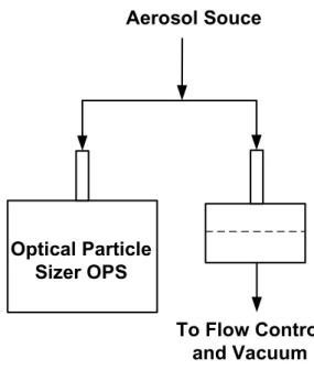
3. Clean the filter cartridge before placing the new filter in it. 4. Co-locate the two instruments as shown in figure 1.
Aerosol Souce
Optical Particle
Sizer OPS
To Flow Control
and Vacuum
Figure 1. Experimental setup for gravimetric calibration
5. To avoid test aerosol filling up the optical chamber, DO NOT hook up the test aerosol to the OPS before starting the OPS pump.
6. Start the OPS. If the “Pump Always On” is enabled, the pump should be running after warm up. 7. Introduce the aerosol of interest into the OPS and the external filter measurement system, and start
the measurement. Since the amount of mass collected by the filter depending on the aerosol density, size distribution and concentration, you need to adjust the sample time appropriately to get reliable mass measurement.
8. Stop the measurement. Take the filter out and measure it with the microbalance.
9. Using the mass collected on the external filter, calculate the mass concentration by using the equation shown below:
Mass concentration= Mass Collected FlowRate×SampleTime
1. Weight the new filter with a microbalance. You may need to minimize the static charge effect by exposing the filter to a bipolar ion source before weighting it.
2. Clean the filter cartridge before placing the new filter in it. Put the assembly back to the OPS. Make sure the assembly is secured to avoid leaking.
3. To avoid test aerosol filling up the optical chamber, DO NOT hook up the test aerosol to the OPS before the pump starts.
4. Start the OPS. If the “Pump Always On” is enabled, the pump should be running after warm up. 5. Introduce the aerosol of interest into the OPS, and start the measurement. Since the amount of mass
collected by the filter depending on the aerosol density, size distribution and concentration, you need to adjust the sample time appropriately to get reliable mass measurement.
6. Stop the measurement. Take the filter out and measure it with the microbalance.
7. Using the mass collected on the 37 mm filter, calculate the mass concentration by using the equation shown below:
Mass concentration= Mass Collected Flow Rate × Sample Time The flow rate and sample time are the OPS flow rate and the OPS sample time.
Calculate the effective density
1. Set the OPS particle density to 1 g/cm3, and record the integrated mass concentration. The effective density can be calculated by:
Effective density= mass concentration from the filter
OPS integrated mass concentration×1 g/cm3
Apply the effective density to the OPS (on instrument)
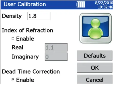
1. Set the OPS particle density to the effective density calculated above. a. On the OPS select the Setup tab at the bottom of the screen. b. Select the Sampling icon.
c. Select the User Calibration icon.
Figure 2. User Calibration screen
2. The OPS will now use this effective density in the displayed mass results both in graphs and tables.
Apply the effective density to the OPS (in software)
1. If data is being collected using Aerosol Instrument Manager® software, the density information is entered using the OPS Properties Dialog Box.
2. When you start the Aerosol Instrument Manager® software and select the OPS 3330 Data type, the
OPS 3330 Properties window opens. Select the Data Setup tab and select the Set Up Channels
button.
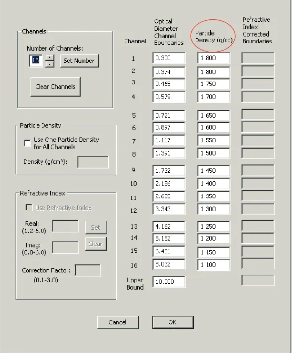
3. If you select the Particle Density check box, you should then enter your effective density in the Density box.
4. If density varies by particle size, it is possible to do a more advanced correction and supply different densities for each size channel. If you uncheck the box in Particle Density portion of the Channel
Figure 3. Channel Setup Screen with different densities
5. The Aerosol Instrument Manager® software will now reflect your effective density value(s) in the mass results both in graphs, tables and statistics.