An Enhanced Synchronized Multi-Channel MAC
Scheme to improve Throughput in VANET
Tripti C
1, Jibukumar M.G
21Department of CSE, Rajagiri School of Engineering and Technology, Cochin, Kerala, India
2Division of Electronics, School of Engineering, Cochin University of Science and Technology, Kerala, India
Abstract: The development of autonomous driving and intelligent transportation demands, fast, reliable and efficient data transmission for various applications in vehicular ad hoc network (VANET). This poses great challenges to the design of a media access control (MAC) protocol that can adapt to the frequent topological shifts. IEEE 1609.4 defines the multi-channel MAC layer implementation in VANET. The multi-channel operation works on a fixed synchronization interval that alternates between a control channel and service channels. The fixed interval leads to poor utilization of limited spectrum resources. In this paper, a multi-channel reliable MAC protocol (MCRMAC), that uses both the control channel and service channel irrespective of the interval to ensure proper and efficient throughput utilization in VANET is proposed. The simulations reveal the performance of the proposed scheme and it outperforms IEEE 1609.4 in terms of throughput.
Keywords: Intelligent Transportation System (ITS), VANET, On Board Unit (OBU), Synchronization Interval.
1.
Introduction
The aim of Vehicular communication is to improve road safety and provide comfort applications for travelers on road. The safety applications need to reach the receivers with a short delay whereas the non-safety applications are delay tolerant. Many research has been done on the routing [1] and application layer to securely route the packets in the network [2]. However, the routing protocols can be effectively only if proper resource allocation is done in the network. Vehicles have high degree of mobility and thus vehicular ad hoc network (VANET) has frequent topology shifts. This work focus on the MAC layer of the system.
Vehicular communication is allotted a frequency band of 5.9 GHz with seven channels [3]. One control channel and six service channels.
IEEE 802.11p along with IEEE 1609.4 defines multi-channel media access control protocol for vehicular ad hoc networks. In IEEE 1609.4 each node follows a synchronization interval where each node will tune to the control channel for 50ms and switches to the service channel in the next 50ms. During the control channel interval, nodes transmit emergency message and WAVE service announcement (WSA) packets [4]. The WSA packets will be transmitted in the control channel during the control channel interval. The node that provides the service is called provider. For WSA transmission, the providers will have to enroll for getting a provider ID (PSID). The WSA frame has details of provider ID, the type of service and the channel details. During the control channel interval, the provider will announce the service and the channel details. The nodes that prefers the service, will respond back on the control channel. The provider and the receiver negotiates over the channel and tunes to the channel during the service channel interval. When the number of nodes increase in the system, the
emergency message as well as the request for WSA packet will be increased and as a result the control channel interval cannot provide enough access to the nodes to support their requirements. The WSA packets if not processed fairly, the service channel becomes under-utilized. Also, the emergency message generated during the service channel should wait for the next control channel interval to transmit it over the control channel. This delays the safety message dissemination. Therefore, the studies have been conducted to dynamically adjust the duration of control channel interval and service channel interval so as to improve the throughput of the system. The key contributions of this paper are summarized as follows:
• In this work, an improved coordinated multi-channel MAC that can improve throughput in VANET is proposed.
• A scheme to identify whether the broadcast message has been successfully received is suggested. This is done by slightly modifying the beacon frame by including a live event table.
• The MAC protocol is also extended with an adaptive contention window that depends on closeness centrality and access category of the vehicle in that range.
• The performance of adaptive contention window for different velocity classes of vehicles is analyzed here.
• The performance of multi-channel scheme, IEEE 1609.4 is compared with the proposed protocol. The results depicts that the proposed protocol shows better performance than IEEE 1609.4 in terms of throughput and average delay in data dissemination.
The rest of this paper is organized as follows: Section II gives an overview of the existing schemes. Section III describes the operation of MCR-MAC. Section IV presents the performance evaluation. Section V gives the concluding remarks.
2.
Literature Survey
Media access control (MAC) in VANET with multi-channel operation is divided into three main categories: (1) Fixed channel coordination scheme (2) Variable channel coordination scheme and (3) Asynchronous multi-channel MAC schemes [14, 15]. Fig.2 shows the fixed channel coordination scheme followed in IEEE 1609.4. In this paper, the focus is on variable channel coordination scheme. The researches under variable channel coordination scheme can be further divided into two based on the application.
(1) Variable control channel interval schemes (2) Extended service channel interval schemes.
In this section we give an overview of existing MAC protocols under both variable control channel interval scheme and extended service channel interval schemes. 2.1 MAC protocols with variable control channel Interval
Variable control channel interval (VCI) multi-channel MAC discussed in [5,6] propose a scheme to dynamically adjust the duration of control channel interval to improve service saturation throughput. An alternate CCHI/SCHI multi- channel coordination scheme with dynamic-tuning on the duration of control channel interval (VCI) is discussed in [7]. Another scheme in [8-10,13], dedicated multi-channel MAC (DMMAC), propose a collision-free and delay-bounded transmission for safety messages using a hybrid channel access scheme. In the above schemes, the service channel resources are wasted during the control channel interval. 2.2 MAC protocols with extended service channel Interval
VEMMAC discussed in [11], retransmit safety packet to increase broadcast reliability during the service channel interval. The scheme also uses the extended transmission mode of IEEE 1609.4 to improve SCH resource utilization. However, at the beginning of both the intervals there is high collision and the nodes might lose the emergency packets (EMG) on the CCH due to extended transmission mode. In [12], VER-MAC is studied, the protocol employs EMG (emergency) packet retransmission and utilizes the CCH during the SCHI for the EMG transmission to improve the EMG broadcast reliability. Also, it utilizes SCH resources using CCHI to enhance service throughput [12]. In order to avoid the frequent switching between CCH and SCH, an improved channel access scheme is presented in [16,17]. It allows a station to remain on the service channel for the calculated data transfer period before returning to the control channel. This is done in order to improve the service channel utilization by cutting CCH to avoid the frequent channel switching between SCH and CCH.
In this paper, a multi-channel reliable MAC protocol (MCR-MAC) is proposed. The scheme is an RSU centered coordination scheme with continuous control channel access specified in WAVE, IEEE 1609.4 suite. The nodes that have no service packets will be listening to the control channel during service channel interval. The scheme allows these nodes to transmit their safety message and WSA packets over the control channel during service channel interval. The report of all the transmission during the SCHI is broadcast by RSU at the starting of the control channel interval. Similarly, the service channels are utilized by the nodes during the control channel interval. The report of all transmissions in
control channel interval is broadcast by the RSU during the start of service channel interval. Thereby it alerts the nodes that miss the broadcast, during any of the interval, to update on the events that happened during the interval. The simulation results indicate that the proposed scheme can improve the throughput in both sparse and dense scenario.
3.
Proposed MCR-MAC
In this section, the motivation and the main contributions of the work is presented. Then the proposed protocol, MCR-MAC and its operation is elaborated.
3.1 Motivation and Contributions
IEEE 1609.4 protocol suite in WAVE supports multi-channel operation in VANET. Four types of channel access techniques are discussed in WAVE [4][5]. They are the continuous CCHI, alternate CCHI/SCHI, Immediate and Extended access. The various channel switching schemes are shown in figure 1.
Figure 1. 1609.4 Channel switching schemes [4]
coordination scheme for VANET works with an alternate CCH/SCH interval scheme. The fixed synchronization interval of IEEE 1609.4 is shown in Fig.4. The high degree of mobility of vehicles with frequent topology shifts is not considered in the existing MAC schemes of VANET for varying density. The proposed scheme follows RSU- based flexible synchronization interval that follows continuous access scheme specified in the IEEE 1609.4 protocol. The synchronization interval operation of MCR-MAC is shown in Fig.4.
Figure 2. Synchronization interval of IEEE 1609.4 [2] 3.2 RSU-based MCR-MAC Protocol
MCR-MAC utilizes CCH during SCHI for broadcasting the emergency and WSA packet. The data-structure of beacon, emergency packet is shown in fig.3 a and b respectively. The details of all the broadcast messages will be recorded by the RSU in the RSU report table. Each node, maintains a channel usage list regarding the usage of channels among the nodes in its connectivity. The structure of the report table and channel usage list is shown in table. 1a and 1b respectively. During the next control channel interval, the report table of RSU is broadcast. Similarly the report of all the messages in the control channel interval is recorded and broadcast by the RSU in the next service channel interval. The safety and WAVE service announcements (WSA) messages are transmitted on the control channel. WSA messages are transmitted by the service providers who offer certain comfort applications to the travelers on road. MCR-MAC, uses the same WSA format as that of IEEE 1609.4. The nodes that are willing to offer a service should first register to get a provider ID. IEEE 1609.4 standard does not say anything about how the channels are allocated to service providers. This protocol works with an assumption that each service channel is divided into slot. When a node sees a WSA packet on CCH, it checks whether the provider ID matches the service requirement of the node. If it matches, the node will check its channel usage list and see whether any of the nodes in its connectivity is using the channel. If no other node is accessing the channel, the node sends an acknowledgement to the provider with channel of both
sender and receiver. Then both the nodes switches to the slot for communication and the channel usage list is updated. The data-structures used for beacon frame and emergency message frame from the node is as given in Fig.3 (a) and (b):
Figure 3(a). Beacon frame of a node
Figure 3(b). Emergency message format
Table 1(a). Report table maintained by RSU No
de
Message ID
TT L
Messag e Type
Area Cod e
Densit y at the Area A
… N
Total nodes in the RSU Range
Table 1(b). Channel usage list maintained by the node.
Algorithm 1 gives the operation of MCR-MAC Input: Time, Vehicle speed, position, ID
Step1: If Tsynch=(Tcch|| Tsch) Step 2: Report_RSU() Step 3: Broadcast_Request() Step 4: End
Broadcast_Request() Step 1: If T==idle(AIFS) Step 2: Start_backoff(0,CW) Step 3: If sense_channel()==0 Step 4: Backoff=Backoff-1 Step 5: If Backoff==0 Step 6: Transmit() Step 7: Else
Step 8: goto Step 1
The operation of MCR-MAC is detailed here as shown in Algorithm 1.
• The synchronization interval is divided into two parts, the control channel interval and the service channel interval. The control channel is further divided into three, the RSU reporting phase, the beacon phase and the contention phase.
• During the RSU reporting phase, the RSU transmits a report of the entire communication that happened on the previous service channel interval. Table 1.a shows the details
1 2
of report table maintained by RSU. This is done for updating all nodes on CCH about the events that happened during the SCHI. On hearing this, the nodes update their tables with the obtained details.
• In the beacon phase, the nodes update their position, speed and channel details and live event list.
• Contention mechanism is used in the third phase. Each node follows the csma/ca scheme mentioned in EDCA for channel access. Table 1.b gives the details of channel usage list maintained by the nodes. Upon receiving a WSA message, the receiver checks the channel usage list to know if the channel mentioned is in use by any of the members in its range. If it is not used by its neighbors, the receiver sends an ACK on the control channel. When other nodes hear this ACK signal, they update their channel usage list.
• At the service channel interval, it follows a continuous access scheme as referred in WAVE –IEEE 1609.4 protocol suite. The nodes that are not involved in any service data traffic are available in the control channel. Those nodes listen to the control channel during the service channel interval. The RSU broadcast the report of all transmissions during the service channel interval.
• At SCHI, the nodes that are on control channel will continue to transmit emergency message and service announcement. The activities of the nodes during this interval is broadcast during the starting of the control channel interval.
Two scenarios are considered here. In the first case, the scheme is done without considering the mobility and density of vehicles. It takes a non-overlapping contention window and found that the performance decreases as the number of nodes increase. Therefore in the second scheme, an adaptive non-overlapping contention window considering velocity of the node at the instant, closeness centrality and the effect of the access category at that instant is considered. The scheme is found to have more performance when compared to the first scheme. Algorithm 2 describes the adaptive contention window used for VANETs.
Algorithm 2 Adaptive Contention Window scheme
Input: Time, Vehicle speed, position, ID, Range Step1: for every node in the range of RSU Step 2: Calculate TTL(i,t)
Step 3: if TTL(i,t)<10 Step 4: Calculate Priority() Step 5: if Priority<N/2
Step 6: Select CW from [0,7] Step 7: Backoff=Backoff-1 Step 8: If Backoff==0 Step 9: Transmit() Step 10: else
Step 11: goto Step 1 Step 12: if Priority>N/2
Step 13: Select CW from [8,15] Step 14: Backoff=Backoff-1 Step 15: If Backoff==0 Step 16: Transmit() Step 17: else
Step 18: goto Step 1 Step 19: End
Step 20: End
Step 21: End //Priority()
Input: Time, Vehicle speed, position, ID, Range Step 1: closeness(i,t)= Degree in (Range/2) Step 2: Effectof AC=AC(i,t)/2
Step 3: Priority=closeness(i,t)*Effect of AC Step 4: End
Each node calculates the time to live value. If the time to live value is less than 10ms, priority value is calculated. This value indicates its importance of its transmission among other nodes. The nodes that has high priority value has more chance for transmission whereas the nodes that has less importance will have low priority. The scheme tries to provide a differentiated channel access reducing the number of packet drops. The broadcast systems do not have an acknowledgement scheme to identify the collisions. Therefore a scheme to identify whether packets have been dropped is necessary to evaluate the performance of the broadcast system. In this scheme, each broadcast message has an IDtable in its data structure. This includes the ID’s of all live events in that range. If a node has transmitted an event earlier and if it is a live event, it will get its ID recorded in the table of its neighbors. Therefore, when it receives a beacon from any of the neighbors, it can check the ID table and if it do not see its own ID, It will re-initiate the transmission. If the transmission is successful, the node that has transmitted the ID can get the ID back from the transmission of its neighbors. For every unsuccessful transmission, the node calculates the priority and follows the same procedure.
4.
Simulation and Results
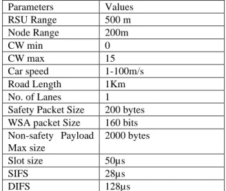
This paper discusses the concept of scheduling synchronization interval, along with an adaptive contention window based MAC such that the system throughput is maximized. To validate the proposed protocol, an event- driven simulation in MATLAB is done. The parameter values used are given in Table 2.
Table 2. Simulation Parameters
Parameters Values
RSU Range 500 m
Node Range 200m
CW min 0
CW max 15
Car speed 1-100m/s
Road Length 1Km
No. of Lanes 1
Safety Packet Size 200 bytes WSA packet Size 160 bits Non-safety Payload
Max size
2000 bytes
Slot size 50µs
SIFS 28µs
DIFS 128µs
contention window based scheme. The response of channel access based on the velocity of vehicles is also studied to demonstrate the fairness in channel access with the scheme. 4.1 Estimated number of collisions for non-safety packets
Consider the probability of a non-safety successful transmission as Ps. Let the probability of collision be Pc. A node will successfully access the channel only when no other nodes is accessing the channel. Each node will sense the channel for a short inter frame space before attempting a transmission. The inter frame space depends on the priority of the access category. After sensing the channel free for the inter frame space, the nodes select a random back off value from the interval [0, Contention Window]. A contention window is an interval from which a node will select randomly a back off value to wait before attempting transmission. Therefore, a node will have to sense the medium for a certain amount of time before attempting transmission. Let this waiting time be tw. It is given by the equation 5. ]) , 0 ([ CW random IFS
tw= + (1)
Where CW is the contention Window, CW is considered ‘m’ here.
Only two types of packets are considered here, the safety packet and the non-safety packet. Safety packet has an IFS with 2 and non-safety has an IFS with 9. The total waiting time in slots is given by equation 5. Therefore the waiting time falls in the range [2, 9+m]. Let the upper bound of waiting time be ‘W’ where
m
W=9+ (2)
Considering the scheme analytically, let the probability of no nodes to have same waiting time be ‘q’ and the probability of collision be ‘p’. The probability of collision of nodes can be represented by Binomial distribution.
Total possible outcomes =(W−1)N (3) Probability of success to is given by the eqn. (4)
N W x N s W x W N P
− = − − = 1 1 1 ) ( (4) The expected number of successful transmission is given bys s N P
p
E[ ]= * (5)
Probability of collision is given by eqn. 6. Where
− − =
− = − N W x N c W x W N P 1 1 1 ) ( 1 (6) The throughput, S is defined as the number of bits transferred successfully in unit time.a s T Payload E p E
S= [ ] [ ]
(7) Where Ta denotes the total time used for delivering that amount of data and E[Payload] is the average packet size. The contention window with overlapping interval is also studied in this work. The probability of success is given by the eqn. (8).
N W C M x N N C M x N s W i W N W x W N P
− = − + − = − − + −= ( ) 1
1
1
1 ( )
) (
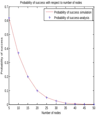
(8) Where W is the maximum window size of the entire system. M represent the maximum value of first window and C represents the minimum value of the second window. Figure 5 a shows the probability of success with non-overlapping window scenario (both simulation and analytically), that the protocol will encounter with respect to the varying number of nodes. As the number of nodes increases, the competition for channel access increases and there are chances for more number of vehicles to choose the same waiting time which leads to collision. Fig. 5 b shows the probability of success with overlapping window (both simulation and analytically), that the protocol will encounter with respect to varying number of nodes. The overlapping scheme shows a slightly better performance than the non-overlapping scenario. Fig. 5 c and d, shows the performance comparison between IEEE 1609.4 and the proposed MCR-MAC with respect to the average delay and the throughput of service packets based on varying number of nodes. The throughput of the proposed scheme is higher than IEEE 1609.4. This is because of utilizing the CCH during SCHI and SCH during CCHI. In MCR-MAC, while considering the saturation scenario, whenever a packet encounters a collision, it is dropped and the procedure is initiated again.
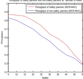
1609.4 as it utilizes SCH resources for data transmission during CCHI. Fig. 5e shows the average throughput of safety and non-safety packets with respect to the varying number of nodes. The scenario is evaluated with equal number of safety and non-safety packets in the network. The results show that safety packets have a better performance than the non-safety packets. However, after 40 nodes, the performance of safety and non-safety packets are decreasing.
Fig. 5f. shows the probability of success of adaptive contention window with overlapping and non-overlapping scenarios. The system performance is better when compared to the fixed contention window scheme. In fixed contention window scheme, the probability of success tends to zero as the number of nodes is 40. However, adaptive contention window gives better performance when compared to fixed contention window scheme. This is because, the nodes can adjust the contention window according to the density and access category in a vehicle.
Initially at the start of both control channel interval and service channel interval, there is a guard band that is used for switching between the intervals. In the control channel interval, the RSU initially broadcast the report of the previous interval. In the initial case, the data in the table is the details of RSU.
Next phase is the beacon phase, the nodes in range get registered with the RSU during this phase. EMG packet is the emergency packet and DP is the data packet. The nodes has emergency packets and data packets to be broadcasted on the control channel. The data packets are the WAVE service packets. In Fig.4 the initial DP is negotiated to be transmitted between the node S1 to S2 over channel 1 and the second packet is scheduled on channel 2 between S3 and S4. During the service channel interval, all nodes other than S1,S2,S3 and S4 are available on the control channel and they broadcast EMG packet as well as DP on the control channel. The channel 2 is allocated to S5 and S6 in the next interval.
5 10 15 20 25 30 35 40 45 50 0
0.1 0.2 0.3 0.4 0.5 0.6 0.7
Probability of success with respect to number of nodes
Number of nodes
P
ro
b
a
b
il
it
y
o
f
s
u
c
c
e
s
s
Probability of success simulation Probability of success-analysis
Figure 5a. Probability of success with respect to number of nodes
Figure 5b. Probability of success for overlapping window with respect to the nodes
5 10 15 20 25 30 35 40 45 50
10 20 30 40 50 60 70 80 90
Nodes
A
v
e
ra
g
e
d
e
la
y
Average delay vs. Number of nodes
Average delay-MRMAC(Safety) Average delay-MCRMAC (Non-safety) Average Delay- IEEE 1609.4(Safety) Average Delay-IEEE 1609.4(Non-Safety)
Figure 5c. Average delay with respect to varying nodes.
5 10 15 20 25 30 35 40 45 50
0 0.1 0.2 0.3 0.4 0.5 0.6 0.7 0.8 0.9
Nodes
A
v
e
ra
g
e
T
h
ro
u
g
h
p
u
t
Average Throughput vs. Number of nodes
Average Throughput (MCR-MAC) Average Throughput (IEEE 1609.4)
5 10 15 20 25 30 35 40 45 50 0.2
0.3 0.4 0.5 0.6 0.7 0.8 0.9 1
Throughput of safety packets and non-safety packets vs. Number of nodes
Nodes
T
h
ro
u
g
h
p
u
t
Throughput of Safety packets (MCR-MAC) Throughput of non-safety packets (MCR-MAC)
Figure 5e. Throughput of safety and non-safety packets with respect to the number of nodes.
Figure 5f. Probability of success for adaptive contention window for overlapping and non-overlapping scenario along with probability of success for non-adaptive CW with respect to varying nodes having 50% safety and 50% non-safety packets.
The resource allocation in VANET is challenging due to the dynamic topology of vehicles. Both safety and non-safety applications must be allocated channels irrespective of the vehicle velocity. In MCR-MAC, the sojourn (residence time) time of the vehicle is calculated first. This value depends on the location and velocity of the vehicle at that instant. In the simulation, the road length is 1 Km and the maximum speed of the vehicle is taken as 100m/s. Therefore, the vehicle with maximum speed can cover the zone in a residence time of 10s. MCR-MAC, considers the vehicles that has a residence value less than 10 seconds. The protocol also considers the effect of the packet inside the vehicle in the zone at that instant. In MCR-MAC, the mobility and the packet type of the vehicle is considered. However, the packet inside the vehicle is considered more than the residence time of the vehicle. This ensures that the system has better fairness than IEEE1609.4 protocol, in delivering packets for fast, average and slow speed vehicles. Fig.5g shows the fairness in channel access with respect to the velocities of vehicles for varying nodes for overlapping window. In simulation, 40% of the total number of nodes considered is working on slow and fast pace and 20% working with medium pace. The fairness in MCR-MAC is calculated as shown in eqn. (9).
)
_
/
/
(
)
_
_
/
/
(
)
(
request
f
m
s
N
processed
request
f
m
s
N
i
F
=
(9) Here, N(s/m/f_request_processed) is the number of slow/medium/fast request processed in the system out of the total number of slow/medium/fast request generated out of the total number of vehicles considered.
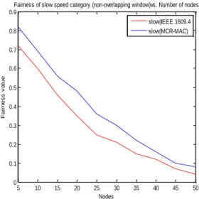
In fig.5 g (i) shows the fairness of slow moving vehicle, in fig. 5.g. (ii), the fairness for fast moving vehicles are analyzed and fig.5.g (iii) shows the fairness of medium pace vehicles all with overlapping window scheme. The performance is good for lower number of requests. However, as the number of nodes increases, the performance degrades. This is due to the increasing number of same type of packets in different vehicles with similar velocity. An adaptive contention window scheme is studied to improve the fairness. The results of the adaptive window scheme with non-overlapping window is studied in Fig.5h.
5 10 15 20 25 30 35 40 45 50
0 0.1 0.2 0.3 0.4 0.5 0.6 0.7 0.8
Fairness for slow speed category (overlapping window) vs. Number of nodes
Nodes
F
a
ir
n
e
s
s
V
a
lu
e
slow(IEEE 1609.4) slow(MCR-MAC)
Figure 5g (i). Fairness of slow speed category
5 10 15 20 25 30 35 40 45 50 0
0.1 0.2 0.3 0.4 0.5 0.6 0.7 0.8
Fairness for high speed category (overlapping window)vs. Number of nodes
Nodes
F
ai
rn
es
s
va
lu
e
fast(IEEE 1609.4) fast(MCR-MAC)
Figure 5g (ii). Fairness of high speed category
5 10 15 20 25 30 35 40 45 50
0 0.1 0.2 0.3 0.4 0.5 0.6 0.7 0.8 0.9
Nodes
F
a
ir
n
e
s
s
v
a
lu
e
Fairness of medium speed categories (overlapping window) vs. Number of nodes
medium(IEEE1609.4) medium(MCR-MAC)
Fig. 5.g (i)(ii)(iii) Fairness in channel access for vehicle velocity categories (with overlapping window) vs. varying number of nodes compared with IEEE 1609.4 scheme.
5 10 15 20 25 30 35 40 45 50 0
0.1 0.2 0.3 0.4 0.5 0.6 0.7 0.8 0.9
Nodes
F
a
ir
n
e
s
s
v
a
lu
e
Fairness of slow speed category (non-overlapping window)vs. Number of nodes
slow(IEEE 1609.4 slow(MCR-MAC)
Figure 5h (i). Fairness of slow speed category (non-overlapping window)
5 10 15 20 25 30 35 40 45 50 0
0.1 0.2 0.3 0.4 0.5 0.6 0.7 0.8 0.9
Nodes
F
a
ir
n
e
s
s
v
a
le
Fairness of high speed category (non-overlapping window)vs. Number of nodes
fast(IEEE 1609.4) fast(MCR-MAC)
Figure 5h (ii). Fairness of high speed category (non-overlapping window)
5 10 15 20 25 30 35 40 45 50 0
0.1 0.2 0.3 0.4 0.5 0.6 0.7 0.8 0.9
Nodes
F
a
ir
n
e
s
s
v
a
lu
e
Fairness of medium speed category (non-overlapping window) vs. Number of nodes
medium(IEEE 1609.4) medium (MCR-MAC)
Figure 5h (iii). Fairness of medium speed category (non-overlapping window)
Fig. 5h (i),(ii),(iii). Fairness in channel access for vehicle velocity categories (with non-overlapping window) vs. varying number of nodes.
The graphs 5.h (i)-(iii), shows that adaptive window scheme with non-overlapping window shows a better performance for vehicles with medium velocity. The adaptive non-overlapping window has a higher performance in all the velocities than the non-adaptive overlapping window scheme.
5.
Conclusions
This paper proposes MCR-MAC that allows nodes to continuously utilize control channel. The scheme permits the nodes to broadcast emergency packets and WSA packets during SCHI and exchange service packets during CCHI. The simulation results show that the proposed scheme outperforms the IEEE 1609.4 protocol suite in terms of throughput and average delay in data dissemination. An adaptive contention window scheme considering velocity, location and access category in a vehicle at an instant is discussed in MCR-MAC to improve the system performance. Overlapping and non-overlapping window scenarios are studied and the results show that an adaptive contention window scheme with non-overlapping window works well for less number of nodes and the adaptive window with overlapping scheme can have better performance than non-overlapping scheme for larger number of nodes.
References
[1] Murugan, Kalpana and A. K. Pathan. “A Routing Algorithm for Extending Mobile Sensor Network's Lifetime using Connectivity and Target Coverage,” International Journal of Communication Networks and Information Security, Vol.11, No.2, pp: 290-296, August 2019.
[2] M. Saleh, L. Dong, A. Aljaafreh, N. Al-Oudat, “Secure Location-Aided Routing Protocols with Wi-Fi direct for Vehicular Ad hoc Networks,” International Journal of Communication Networks and Information Security,Vol.12, No.1, pp. 10-18, April 2020.
[3] Ahmed SAM, Ariffin SHS and Fisal N. “Overview of wireless access in vehicular environment (WAVE) protocols and standards,” Indian Journal of Science and Technology; Vol. 6, No. 7, pp. 4994–5001, July 2013.
[4] M. van Eenennaam, A. van de Venis, and G. Karagiannis, “Impact of IEEE 1609.4 channel switching on the IEEE 802.11p beaconing performance,” in Proceedings of the IFIP Wireless Days (WD ’12), IEEE, Dublin, Republic of Ireland, pp. 1–8, November 2012.
[5] Wang, Q., Leng, S., Fu, H. & Zhang, Y., “An IEEE 802.11 p-based Multichannel MAC Scheme with Channel Coordination for Vehicular Ad hoc Networks,” IEEE Transactions on Intelligent Transportation Systems, Vol. 13, No.2, pp. 449-458, June 2012.
[6] Q. Wang, S. Leng, H. Fu and Y. Zhang. "An Enhanced Multi-channel MAC for the IEEE 1609.4 based Vehicular Ad Hoc Networks,” In Proc. of the INFOCOM Conference on Computer Communications Workshops, San Diego, CA, USA, March 15-19, 2010.
[7] Nguyen, V, Khanh, TT, Pham, X‐Q, Lee, G‐W, Huh, E‐N. “Performance analysis of adaptive MAC protocol in VANETs considering the potential impact on throughput and transmission delays,” International Journal of Communication Systems, Vol.33, No.1, September 2019.
[8] Lu, Ning et al. “A Dedicated Multi-Channel MAC Protocol Design for VANET with Adaptive Broadcasting,” 2010 IEEE Wireless Communication and Networking Conference, Sydney, NSW, Australia, April 2010.
medium access control protocols for vehicular ad hoc networks,” International Journal of Distributed Sensor Networks, Vol. 15, No.2, February 2019.
[10] Mohamed, Hadded & Muhlethaler, Paul & Laouiti, Anis & Zagrouba, Rachid & Saidane, Leila. “TDMA-based MAC Protocols for Vehicular Ad Hoc Networks: A Survey, Qualitative Analysis and Open Research Issues,” IEEE Communications Surveys & Tutorials, Vol. 17, No.4, Fourthquarter, pp. 2461 – 2492, June 2015.
[11] Duc Ngoc Minh Dang, Hanh Ngoc Dang, Cuong The Do and C. S. Hong, "An Enhanced Multi-channel MAC for Vehicular Ad Hoc Networks," 2013 IEEE Wireless Communications and Networking Conference (WCNC), Shanghai, China, pp. 351-355, 7-10 April 2013.
[12] D. N. M. Dang, C. S. Hong, S. Lee and E. Huh, "An Efficient and Reliable MAC in VANETs," IEEE Communications Letters, Vol. 18, No. 4, pp. 616-619, April 2014.
[13] Liu, L.; Xia, W.; Shen, L. “An adaptive multi-channel MAC protocol with dynamic interval division in vehicular environment,” In Proceedings of the first International Conference on Information Science and Engineering, Nanjing, China, pp. 2534–2537, 26–28 December 2009.
[14] Han, Chong & Dianati, Mehrdad & Tafazolli, Rahim & Kernchen, Ralf., “Asynchronous Multi-Channel MAC for Vehicular Ad Hoc Networks,” IEEE Vehicular Networking Conference (VNC), Amsterdam, Netherlands, pp.109-115, 14-16 November 2011.
[15] Tripti C et al., “An asynchronous multi-channel MAC for improving channel utilization in VANET,” Proceedings of 7th International Conference on Advances in Computing & Communications, ICACC-2017, Cochin, India, pp.607-614, 22- 24 August 2017.
[16] L. Liu, C. Wang, H. Zhang and L. Wu, "Variable SCH Interval Multichannel Medium Access Control Scheme with Unsaturated Channel in VANETs," Proceedings of IEEE International Conference on Communication Systems (ICCS 2016), Shenzhen, China, 14-16 December 2016.
![Figure 1. 1609.4 Channel switching schemes [4]](https://thumb-us.123doks.com/thumbv2/123dok_us/8121384.2153992/2.892.511.803.423.826/figure-channel-switching-schemes.webp)
![Figure 2. Synchronization interval of IEEE 1609.4 [2]](https://thumb-us.123doks.com/thumbv2/123dok_us/8121384.2153992/3.892.468.823.126.1060/figure-synchronization-interval-ieee.webp)