Direct Power Control By Using Matrix Converter Based UPFC
Ravikumar Reddy P
1Firoz Ali Mohammed
2,
1
PursuingM.Tech in the field of POWER INDUSTRIAL DRIVES
2Assoc.prof &, head of the EEE Deportment
ABSTRACT
This paper describes direct power control (DPC) by using Matrix converter based Unified power flow controller (UPFC). The basic problems of UPFC’s are discussed, however this paper proposes an alternative solution for direct power control using a direct ac-ac converter called a matrix converter. The pulse width modulation control technique developed and presented in this paper is based on space vector approach. This paper presents the complete space vector model of a three phase to three phase matrix converter topology. Theoretical principles of direct power control (DPC) based on sliding mode control techniques are established for a matrix converter based UPFC dynamic model including the input filter.
Matrix converters (MCs) allow the direct ac-ac power conversion without dc energy storage links, matrix converter is a bidirectional power flow converter that uses semi converter switches arranged in the form of matrix array. Therefore, the matrix converter based unified power flow controller (MC-UPFC) has reduced cost, capacitor power losses and volume with higher reliability By selecting an appropriate matrix converter switching state, line active and reactive power, together with ac supply reactive power, can be directly controlled, and guaranteeing good steady-state and dynamic responses. The line active and reactive power linear controllers based on a modified Venturini high-frequency PWM modulator compared with direct power controller (DPC) by using MC-UPFC; guarantee faster responses without overshoot , presenting no cross-coupling in dynamic and steady-state responses and no steady steady-state error. Experimental results of direct power controllers for MC based UPFC shows decoupled active and reactive power control and fast response times.
Key words- DPC, UPFC, MC, reactive power, Power control.
INTRODUCTION
In the last few years, electricity market deregulation, together with growing economic, environmental, and social concerns, has increased the difficulty to burn fossil fuels, and to obtain new
licenses to build transmission lines (rights-of-way) and high-power facilities. This situation started the growth of decentralized electricity generation (using renewable energy resources).
Unified power-flow controllers (UPFC) enable the operation of power transmission networks near their maximum ratings, by enforcing power flow through well-defined lines. These days, UPFCs are one of the most versatile and powerful flexible ac transmission systems (FACTS) devices.
The UPFC results from the combination of a static synchronous compensator (STATCOM) and a static synchronous series compensator (SSSC) that shares a common dc capacitor link.
The existence of a dc capacitor bank originates additional losses, decreases the converter lifetime, and increases its weight, cost, and volume. In the last few decades, an increasing interest in new converter types, capable of performing the same functions but with reduced storage needs, has arisen. These converters are capable of performing the same ac/ac conversion, allowing bidirectional power flow, guaranteeing near sinusoidal input and output currents, voltages with variable amplitude, and adjustable power factor. These minimum energy storage ac/ac converters have the capability to allow independent reactive control on the UPFC shunt and series converter sides, while guaranteeing that the active power exchanged on the UPFC series connection is always supplied/absorbed by the shunt connection.
Conventional UPFC controllers do not guarantee robustness the dependence of the matrix converter output voltage on the modulation coefficient was investigated, concluding that MC-UPFC is able to control the full range of power flow. Recent nonlinear approaches enabled better tuning of PI controller parameters. Still, there is room to further improve the dynamic response of UPFCs, using nonlinear robust controllers .
In the last few years, direct power control techniques have been used in many power applications, due to their simplicity and good performance. In this paper, a matrix converter- based UPFC is proposed, using a direct power control approach (DPC-MC) based on an MC-UPFC dynamic model (Section II).
is based on sliding mode-control techniques , allowing the real-time selection of adequate matrix vectors to control input and output electrical power. Sliding mode-based DPC-MC controllers can guarantee zero steady-state errors and no overshoots, good tracking performance, and fast dynamic responses, while being simpler to implement and requiring less processing power, when compared to proportional-integral (PI) linear controllers obtained from linear active and reactive power models of UPFC using a modified Venturing high-frequency PWM modulator.
The dynamic and steady-state behavior of the proposed DPC-MC P, Q control method is evaluated and discussed using detailed simulations and experimental implementation (Sections IV and V). Simulation and experimental results obtained with the nonlinear DPC for matrix converter-based UPFC technology show decoupled series active and shunt/series reactive power control, zero steady state error tracking, and fast response times, presenting faultless dynamic and steady state responses.
EXISTING SYSTEM LIMITATIONS:
Conventional UPFC controllers do not guarantee robustness. The existence of a dc capacitor bank originates additional losses, decreases the converter lifetime, and increases its weight, cost, and volume. Minimum Storage Capability and Conventional UPFC controllers do not guarantee robustness.
PROPOSED SYSTEM MERITS:
Unified power-flow controllers (UPFC) enable the operation of power transmission networks near their maximum ratings, by enforcing power flow through well-defined lines.MC-based UPFC (MC-UPFC) has reduced volume and cost, reduced capacitor power losses, together with higher reliability. As a result, line active and reactive power, together with ac supply reactive power, can be directly controlled by selecting an appropriate matrix converter switching state guaranteeing good steady-state and dynamic responses.
APPLICATIONS:
Many Power Applications,
It’s controlled the input and Output Electrical Powers (ex. Transformers.)
Transmission line Power Control as well as Power Factor Control
MODELING OF THE UPFC POWER
SYSTEM
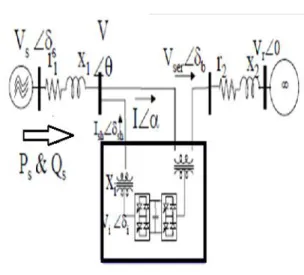
A simplified power transmission network using the proposed matrix converter UPFC is
presented in Fig. 1, where Vs and VRare, respectively, the sending-end and receiving-end sinusoidal voltages of the Grand GR generators feeding load ZL. The matrix converter is connected to transmission line 2, represented as a series inductance with series resistance (L1 and R2), through coupling transformers T1 and T2. Fig. 2 shows the simplified three-phase equivalent circuit of the matrix UPFC transmission system model.
For system modeling, the power sources and the coupling transformers are all considered ideal. Also, the matrix converter is considered ideal and represented as a controllable voltage source, with amplitude Vc and phase . In the equivalent circuit, is the load bus voltage? The DPC-MC controller will treat the simplified elements as disturbances. Considering a symmetrical and balanced three-phase system and applying Kirchhoff laws to the three-phase equivalent circuit (Fig. 2), the ac line currents are obtained in coordinates The active and reactive power of sending end generator are given in coordinates by
= wIq− Id+ (VLd–VRod) (1) = wId− Iq+ (VLq–VRoq) (2)
The active and reactive power of sending end generator are given in coordinates by
Assuming VroA
= − (3)
Assuming Vrod and Vsd = Vd as constant and a rotating reference frame synchronized to the Vs source so that Vsq = 0, active and reactive power P and Q are given by (4) and (5) respectively.
P=Vd Id (4) Q= −Vd Iq (5)
Fig.2. Three – phase equivalent circuit of the matrix UPFC and transmission line
Fig.3. Transmission network with matrix converter
MATRIX CONVERTER
This chapter aims to give a general description of the basic features of a three phase to three phase matrix converter in terms of performance and of technological issues. This chapter does not require to the reader a special knowledge of the matrix converter technology. It is worth noting that the three phase to three phase configuration is just one of the possible direct AC-AC converter topologies, which are not in the scope of the present report. The matrix converter has several advantages over traditional rectifier-inverter type power frequency converters. It provides sinusoidal input and output waveforms, with minimal higher order harmonics and no sub harmonics; it has inherent bi-directional energy flow capability; the input power factor can be fully controlled. Last but not least, it has minimal energy storage requirements, which allows to get rid of bulky and lifetime- limited energy-storing capacitors.
But the matrix converter has also some disadvantages. First of all it has a maximum input output voltage transfer ratio limited to @ 87 % for sinusoidal input and output waveforms. It requires more semiconductor devices than a conventional AC-AC indirect power frequency converter, since no monolithic bi-directional switches exist and consequently discrete unidirectional devices, variously arranged, have to be used for each bi-directional switch. Finally, it is particularly sensitive to the disturbances of the input voltage system. The comments and remarks made in this chapter are somewhere supported by simulation results obtained from a simplified simulation model.
THE TOPOLOGY
The matrix converter consists of 9 bi-directional switches that allow any output phase to be connected to any input phase. The circuit scheme is shown in Fig.2.1.
The input terminals of the converter are connected to a three phase voltage-fed system, usually
the grid, while the output terminal are connected to a three phase current- fed system, like an induction motor might be. The capacitive filter on the voltage-fed side and the inductive filter on the current- voltage-fed side represented in the scheme of Fig.2.1 are intrinsically necessary. Their size is inversely proportional to the matrix converter switching frequency. It is worth noting that due to its inherent bi-directionality and symmetry a dual connection might be also feasible for the matrix converter: a current- fed system at the input and a voltage- fed system at the output.
Fig.2.1. Circuit scheme of a three phase to three phase matrix converter (a,b,c are at the input terminals. A,B,C are at the out put terminals)
With nine bi-directional switches the matrix converter can theoretically assume 512 (29) different switching states combinations. But not all of them can be usefully employed. Regardless to the control method used, the choice of the matrix converter switching states combinations (from now on simply matrix converter configurations) to be used must comply with two basic rules. Taking into account that the converter is supplied by a voltage source and usually feeds an inductive load, the input phases should never be short-circuited and the output currents should not be interrupted.
From a practical point of view these rules imply that one and only one bi-directional switch per output phase must be switched on at any instant. By this constraint, in a three phase to three phase matrix converter 27 are the permitted switching combinations.
UNIFIED
POWER
FLOW
CONTROLLER
practically all power flow control and transmission line compensation problems, using solid state controllers, which provide functional flexibility, generally not attainable by conventional thyristor controlled systems.
The UPFC is a combination of a static synchronous compensator (STATCOM) and a static synchronous series compensator (SSSC) coupled via a common DC voltage link. It is capable of controlling simultaneously or selectively, all the parameters affecting the power flow in a transmission line. The parameters usually are voltage, impedance and phase angle.
Fig.: Block diagram of Unified Power flow controllers. This topology offers three degrees of freedom or more precisely - four degrees of freedom (two associated with each VSC) with one constraint (active powers of the VSCs must match). Therefore, a fundamentally different range of control options is available compared to STATCOM or SSSC. The UPFC can be used to control the flow of active and reactive power through the line and to control the amount of reactive power supplied to the line at the point of installation.
While operating both inverters as a UPFC, the exchanged power at the terminals of each inverter can be imaginary as well as real.
While operating both inverters as a UPFC, the exchanged power at the terminals of each inverter can be imaginary as well as real. Representative of the last generation of FACTS devices is the Unified Power Flow Controller (UPFC). The UPFC is a device which can control simultaneously all three parameters of line power flow (line impedance, voltage and phase angle).
The UPFC combines together the features of the Static Synchronous Compensator (STATCOM) and the Static Synchronous Series Compensator (SSSC). In practice, these two devices are two Voltage Source Inverters (VSI’s) connected respectively in shunt with the transmission line through a shunt transformer and in series with the transmission line through a series transformer, connected to each other by a common dc link including a storage capacitor.
The shunt inverter is used for voltage regulation at the point of connection
Injecting an opportune reactive power flow into the line and to balance the real power flow exchanged between the series inverter and the transmission line. The series inverter can be used to control the real and reactive line power flow inserting an opportune voltage with controllable magnitude and phase in series with the transmission line
Thereby, the UPFC can fulfill functions of reactive shunt compensation, active and reactive series compensation and phase shifting. Besides, the UPFC allows a secondary but important function such as stability control to suppress power system oscillations improving the transient stability of power system. The basic components of theUPFCare two voltage source inverters (VSI's) sharing a common dc storage capacitor, and connected to the system through coupling transformers. One VSI is connected in shunt to the transmission system via a shunt transformer, while the other one is connected in series through a series transformer.
The series inverter is controlled to inject a symmetrical three phase voltage system of controllable magnitude and phase angle in series with the line to control active and reactive power flows on the transmission line. So, this inverter will exchange active and reactive power with the line. The reactive power is electronically provided by the series inverter, and the active power is transmitted to the dc terminals. The shunt inverter is operated in such a way as to demand this dc terminal power (positive or negative) from the line keeping the voltage across the storage capacitor Vdc constant.
Fig: Model of UPFC
The mathematical UPFC model has been derived with the aim of being able to study the relations between the electrical transmission system and UPFC in steady and transient conditions.
So, the net real power absorbed from the line by the UPFC is equal only to the losses of the two inverters and their transformers. The remaining capacity of the shunt inverter can be used to exchange reactive power with the line so to provide a voltage regulation at the connection point. The two VSI’s can work independently of each other by separating the dc side. So in that case, the shunt inverter is operating as aSTATCOMthat generates or absorbs reactive power to regulate the voltage magnitude at the connection point. Instead, the series inverter is operating asSSSC that generates or absorbs reactive power to regulate the current flow, and hence the power flows on the transmission line.
The UPFC has many possible operating modes. In particular, the shunt inverter is operating in such a way to inject a controllable current into the transmission line. This current consists of two components with respect to the line voltage: the real or direct component, which is in phase or in opposite phase with the line voltage, and the reactive or quadrature component, which is in quadrature. The direct component is automatically determined by the
requirement to balance the real power of the series inverter. The quadrature component, instead, can be independently set to any desired reference level (inductive or capacitive) within the capability of the inverter, to absorb or generate respectively reactive power from the line.
Two control modes are possible:
1. VAR control mode:the reference input is an inductive or capacitive var request;
1.1. Automatic Voltage Control mode: The goal is to maintain the transmission line voltage at the connection point to a reference value. Instead, the series inverter injecting the voltage controllable in amplitude and phase angle in series with the transmission line influences the power flow on the transmission line. This series voltage can be determined in different ways: Direct Voltage Injection mode: the reference inputs are directly the magnitude and phase angle of the series voltage;
1.2. Phase Angle Shifter Emulation mode: The reference input is phase displacement between the sending end voltage and the receiving end voltage; Line impedance emulation mode: the reference input is an impedance value to insert in series with the line impedance;
2. Automatic Power flow Control mode:
The reference inputs are values of P and Q to maintain on the transmission line despite system changes. In general the shunt inverter will be operated in Automatic Voltage Control mode and the series inverter in Automatic Power Flow Control mode.
SIMULATION DIAGRAM
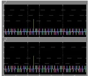
Fig.1: Three phase input voltages & three phase input Currents
Fig. 2: Matrix converter Output Voltage (V), Output Current (I), Active Power (P) & Reactive Power (Q) in normal scale mode
Fig. 3: Direct power control with Matrix converter, Output Voltage, Output Current, Active Power & Reactive Power in Auto Scale mode
Fig. 4: Active power Sliding surface S(ep , t) & Reactive power sliding surface S(eq , t) waveforms in auto scale mode
CONCLUSION
This paper derived direct power controllers for matrix converters connected to power transmission lines as UPFCs, based on sliding mode control techniques. Presented simulation and experimental results show that active and reactive power flow can be advantageously controlled by using the proposed direct power controller (DPC). Results show no steady-state errors, no cross-coupling, insensitivity to nonmodeled dynamics and fast response times, thus confirming the expected performance of the presented DPC methodology. The obtained DPC-MC results were compared to PI linear active and reactive power controllers using a modified Venturini high-frequency PWM modulator.
Despite showing a suitable dynamic response, the PI performance is inferior when compared to DPC. Furthermore, the PI controllers and modulator take longer times to compute. Obtained results show that DPC is a strong nonlinear control candidate for line active and reactive power flow. It ensures transmission-line power control as well as sending end reactive power or power factor control.
REFERENCES
[1] N. Hingorani and L. Gyugyi, Understanding FACTS—Concepts and Technology of Flexible AC Transmission Systems. Piscataway, NJ: IEEE Press/Wiley, 2000.
[2] L. Gyugyi, “Unified power flow control concept for flexible AC transmission systems,” Proc. Inst. Elect. Eng. C, vol. 139, no. 4, Jul. 1992.
controller: A new approach to power transmission control,”IEEE Trans. Power Del., vol. 10, no. 2, pp. 1085–1097, Apr. 1995.
[4] C. Schauder, L. Gyugyi, M. Lund, D. Hamai, T. Rietman, D. Torgerson, and A. Edris, “Operation of the unified power flow controller (UPFC) under practical constraints,” IEEE Trans. Power Del., vol. 13, no. 2, pp. 630–639, Apr. 1998.
[5] T. Ma, “P-Q decoupled control schemes using fuzzy neural networks for the unified power flow controller,” inElectr. Power Energy Syst.. New York: Elsevier, Dec. 2007, vol. 29, pp. 748–748.
[6] L. Liu, P. Zhu, Y. Kang, and J. Chen, “Power-flow control performance analysis of a unified power-flow controller in a novel control scheme,” IEEE Trans. Power Del., vol. 22, no. 3, pp. 1613–1619, Jul. 2007. [7] F. Gao and M. Iravani, “Dynamic model of a space vector modulated matrix converter,” IEEE Trans. Power Del., vol. 22, no. 3, pp. 1696–1750, Jul. 2007. [8] B. Geethalakshmi and P. Dananjayan, “Investigation of performance of UPFC without DC link capacitor,” in Elect. Power Energy Res.. New York: Elsevier, 2008, pp. 284–294, 736-746.
[9] X. Jiang, X. Fang, J. Chow, A. Edris, E. Uzunovic, M. Parisi, and L. Hopkins, “A novel approach for modeling voltage-sourced converterbased FACTS controllers,” IEEE Trans. Power Del., vol. 23, no. 4, pp. 2591–2598, Oct. 2008.
[10] R. Strzelecki, A. Noculak, H. Tunia, and K. Sozanski, “UPFC with matrix converter,” presented at the EPE Conf., Graz, Austria, Sep. 2001.
RAVIKUMAR REDDY P