38
Measuring Small Boats Using
Non-Contact Method
Omar bin Yaakob,a,* Zulkipli Majid,b Mohd Farid Mohd Ariff,b Khairulnizam M.Idris,b Badruzzaman Ahmad,a
a
Marine Technology Centre, Universiti Teknologi Malaysia, 81200 Skudai, Johor Bahru, Johor, Malaysia.
b
Faculty of Geoinformation& Real Estate, Universiti Teknologi Malaysia, 81200 Skudai, Johor Bahru, Johor, Malaysia.
*Corresponding author: [email protected]
Abstract
In designing a ship, offset data or lines plan drawing is the most important information about the ship, since the ship’s performance is derived from such data or drawing. Normally, traditional boats are built without involving proper ship drawings. Therefore, these boats’ performance analysis is difficult without the line drawing. This paper presents a study on boat measurement using photogrammetry technique. The main objective of this study is to develop and test photogrammetry method to obtain the best hull form of a small boat. Initially, the method was tested on small fishing boat model having a length of 2.5 m to assess its accuracy. Once the method reliability had been verified, a more comprehensive method was developed and applied to an actual fishing boat having length of 3.55 m. In this study, Digital Single Lens Reflex camera was used to obtain the three-dimensional (3D) coordinate from captured two-three-dimensional (2D) photograph. Circular retro reflection target tape was used in this study to mark the boat hull according to line of station and buttock line as the referencing purpose. Australis 6.0.6 software was used for image processing to obtain X, Y and Z coordinates of retro reflection target and transferring those coordinates into Maxsurf naval architecture software. The result obtained indicated that the method developed was able to obtain the lines plan of the boat. However, some factors still need to be considered to improve the accuracy of the measurement.
Keywords: Offset data, photogrammetry, hull form, fishing boat.
1. INTRODUCTION
Particular dimensions of boat such as length, breadth, and depth are important parameters to determine the size of the boat. Besides the main particulars, offset data are required to define the hull form of that boat. From the offset data, hydrostatic particulars can be obtained, which then provide the characteristics of the boat. Apart from that, the stability, strength and efficiency of the boat can also be determined once the hull form offsets or drawings are available.
According to Koelman et al. [1], the development of hull form using conventional methods like
manual drawing of lines plan, manual lofting and construction of shell plate developments require not only time, but also expertise, and creating a ship hull design is a cumbersome process, very time consuming and tedious to carry out manually.
To measure the small boat hull form, two methods are commonly used: contact and non-contact methods. The contact method varies from conventional (line lifting) or simple direct tape measurement, to the sophisticated tools such as coordinate measuring machine (CMM). The
non-contact method consists of close range
photogrammetry, terrestrial laser scanning and geodetic theodolite or total station. The accuracy of
39
these measurement methods also varies from centimeter to micron level.
A method to obtain hull form data from existing ships has been introduced by Ahmed et al. [2]. The method used PhotoModeler Pro 5 software to process the photo images. However, the method was only implemented on a small lab-scale model. In this study, different software Austalis 6.0.6 was used to process the image and the method is implemented on an actual boat.
2.LITERATUREREVIEW
Photogrammetry is defined by the American Society for Photogrammetry and Remote Sensing as “the art, science, and technology of obtaining reliable information about physical objects and the environment through processes of recording, measuring, and interpreting photographic images
and patterns of recorded radiant electromagnetic energy and other phenomena” [3]. Photogrammetry allows reconstruction of the position, orientation, shape and also the size of the object just from photographs. These photographs may be in the form of photochemical images or photoelectric images. The photogrammetry method also allows the re-engineering or re-construction of the object shape and analyzing the characteristic of the object without needing physical contact [4].
Photogrammetry uses the principle of triangulation to produce three-dimensional measurement points. The precise location of the point can be determined by mathematically intersecting the converging lines in space. By taking photos from at least two different locations, lines of sight can be developed from each camera to point on the object.
40
These lines of sight sometimes are called rays because of their optical nature, which can be mathematically intersected to produce
three-dimensional points of intersection [5].
Photogrammetry has been used for years as a measuring method in industry. The results by using photogrammetry technique generally fulfill the requirement set by industry. Photogrammtery is indeed so far the best measuring method compared to the other traditional geodetic methods used in industry.
Industrial measurement and measurement done on marine structure in particular are very different compared to traditional photogrammetry method. However, it is still not sufficient to consider if it is possible to solve a particular task at a shipyard only by means of photogrammetry. For the marine industry, some of the factors that have to be considered are [6]:
I. The geometry of the object. II. The surroundings of the object
III. The accessibility of measurement point
IV. Time consumption
According to Ordóñez et al. [7] the
photogrammetry method is able to improve the precision of measurement, time consumption, equipment cost, and ease of manipulation, if compared with direct method. In their experimental study, decks of recreational ship were selected for measurement in order to obtain the area of the deck and time consumption.
3. METHOD
3.1 Data Collection
Data collection process requires some
considerations for measurement process, such as placement of scale bar and photographing object. Scale bar is used for scaling and it is compulsory to utilize essential equipment in every measurement process in order to obtain exact value of model measured. The scale bar is also used as reference in each photograph in order to verify the accuracy of measurement. For ship measurement, the retro target should be placed on the boat hull where camera stations are able to capture the targets from at least three different angles of photograph. Retro
reflective target type was chosen for the measurement in this study. Selection of target size depends mostly on size of the object to be measured. Retro reflection target helps for creating the reflect light effectively from target.
Planning for photographing is required in order to get a complete measurement that covers all targets. To ensure its practically, the image processing should be taken from four or more images from different location, and the angle of camera crossing in range between 60 degrees and 120 degrees, while the angle of reflection should be less than 60 degrees. Thus, for this measurement process, all images of the object should be taken in the form of semi-circle to get covered images. This can ensure that all images target have enough intersection of ray for triangulation process. The distance between the camera and the object can be determined by referring at the distance by which the object should cover the all spaces in the camera screen.
3.2 Images Processing
To determine the 3D coordinate, the image from camera should go through the process of observation and measurement. In this study, the images were taken in JPEG format, and then transferred into Australis 6.0.6 software using Universal Serial Bus (USB) link cable. Australis 6.0.6 software is a photogrametry program used to make automatic 3D measurements of an array of specially coded or uncoded targets placed on or an object of interest [8].
After image captures, images with best quality were selected and put through processing step. The Australis 6.0.6 software was able to determine all the coordinates of target. Digitizing or marking the retro reflection target is crucial in processing step in order to achieve high accuracy of measurement.
After completing the processing step, the model could be viewed in three dimensional (3D)
orientations. The three dimensional (3D)
coordinates from Australis 6.0.6 was then transferred into Maxsurf version 11 software.
41
analysis and construction process. All modules in the range operate from a single 3D surface model which allows design changes to flow through
automatically and facilitates smooth
communication and coordination between different design activities [9].
In Maxsurf software, data of the fiberglass boat could be read as a markers data in .xyz, format, where x represents the offset, y represents the longitude and z represents the height.
3.3 Camera Calibration
In photogrammetry, the accuracy of measurement will be largely determined by the accuracy of the images produced by the digital camera [10]. A digital single lens reflex (DSLR) camera type model Sony DSC-F828 was used for this measurement. The features of this camera include:
8.0 Megapixels (3264 x 2488) resolution
7.1 mm
7x optical zoom
Manual exposure control
In this study, the camera calibration used was self-calibrated. In [11], self-calibration was used as it does not require control point for the camera calibration and at the same time requires very minimum time. Besides, calibration process by self-calibration method is easy to handle.
3.4 Survey Accuracy
The accuracy of three-dimensional (3D)
measurement of photogrammetry method is dependent on the photographic referencing and the constraints of the survey work defined. Besides, features of the three dimensional (3D) Scale and Rotation in Australis 6.0.6 also contribute to enhancement of the accuracy of the measurement.
4. IMPLEMENTATION
In this survey, a 3.55m Cartopper fiberglass boat was chosen. This model is specifically design for fishing and recreation. Figure 2 shows the Cartopper fiberglass boat (12 ft), and its specifications are shown in Table 1.
Figure 2. Cartopper fiberglass boat (12 ft) and specification
Before the measurement process was carried out, retro reflective targets were put on the hull according to line station marked earlier. In this project, targets were placed at six stations. For each station, the target was placed at 9 points but at the chine and keel for the port side only.
Figure 3. Retro reflective targets installed on the boats.
Table 1. Boat specifications
Specification
Length 3.55 m
Breadth 1.07 m
Depth 0.41 m
Capacity 3 – 4 Person
OBM Recommended 5 – 8 HP
42
source is very important in capturing the image. Extra flash was not used because it would give bad exposure towards the retro reflective targets. By using the camera on tripod, vibration could be avoided due to hand shivering while photographing the boat.
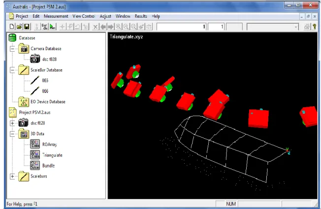
After finishing the photo capture, the process was proceeded with data processing. Austalis 6.0.6 was used in data processing to determine the coordinate
of the target. The data processing can be divided into four steps, which are Relative orientation, Resection, Triangulation and Bundle Adjustment. All steps must be done in order before final coordinates can be determined. The process requires a person to digitize all retro reflection targets for all images. The final value of retro reflection target was determined in Bundle Adjustment process, as shown in Figure 4.
Figure 4. Processing images in Austalis 6.0.6 software
Figure 5. Contact method measurement using strings and rules.
The data obtained after processing by Austalis 6.0.6 were transferred to Maxsurf version 11 for full hull form modeling. To validate the data, measurements were made using the traditional contact method. As seen in Figure 5, strings and rulers were used for measure the hull form. Strings were tied to mark the hull base line, followed by station and buttock line. From the base lines, rulers were use to measure the distance from the base line to the hull surface.
5. RESULTS
43
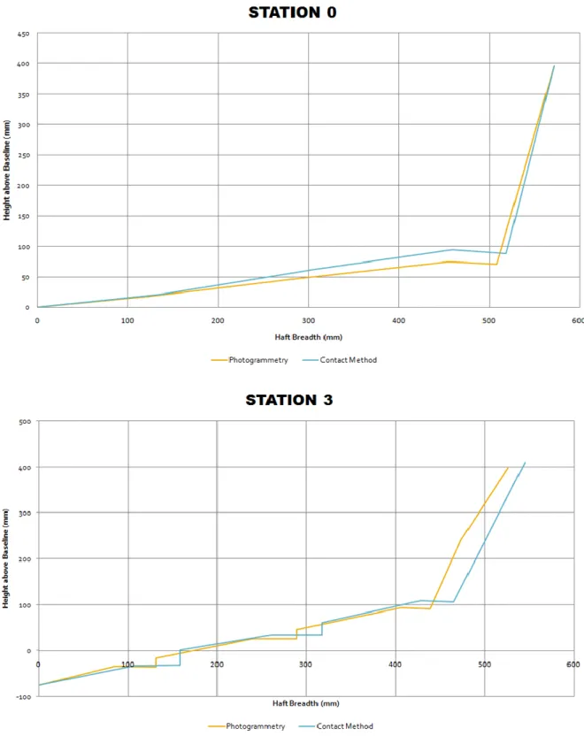
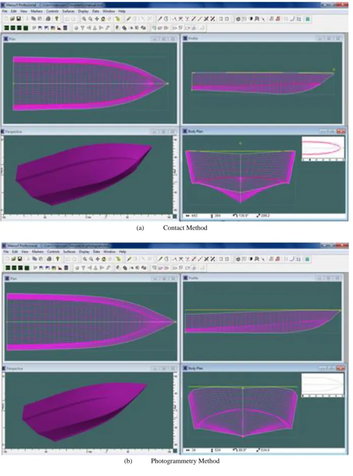
which is better to accurately measure a small boat. A sample plot of two stations (Station 0 and station 3) and the 3D model of the hull developed using
Maxsurf is shown in Figure 6 and 7 respectively, for both methods.
44
(a) Contact Method
(b) Photogrammetry Method
45
Comparisons of the principal particulars are shown in Table 2. The results show only slight variations in length, breadth and depth measured between the two methods.
Table 2. Comparison between contact method and photogrammetry Contact Method (m) Photo- gram-metry (m) Diff. (m) Error (%)
Depth 0.484 0.471 0.013 2.69
Breadth 1.090 1.098 -0.008 -0.73
Length 3.555 3.54 0.015 0.42
5.1 Hydrostatic particulars
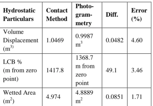
Table 3 shows the hydrostatic particulars and different values between the contact method and the photogrammetry method. Again, the difference of hydrostatic data between the two methods are less than 5%, which is not significant.
Table 3. Comparison of hydrostatic particulars
Hydrostatic Particulars Contact Method Photo- gram-metry
Diff. Error (%)
Volume Displacement (m3)
1.0469 0.9987
m3 0.0482 4.60
LCB % (m from zero point) 1417.8 1368.7 m from zero point
49.1 3.46
Wetted Area
(m2) 4.974
4.8889
m2 0.0851 1.71
6. CONCLUSION
From the measurement process conducted on fiberglass boat using close range photogrammetry, it can be concluded that the close range photogrammetry method is an accurate, reliable, flexible and economical coordinate measuring
system compared with other non-contact
measurement methods. The integration of Australis 6.06 and Maxsurf allows the construction of line drawing.
7. REFERENCES
[1] Koelman, H. J., Horváth, I., and Aalbers, A. (2001). Hybrid representation of the shape of ship hulls. International shipbuilding Progress.48, no3, 247-269.
[2] Ahmed, Y.M., Jamail, A., Yaakob, O.B, (2012). Boat Survey Using Photogrammetry Method, International Review of Mechanical Engineering (IREME) Vol. 6 n. 7, pp. 1643-1647.
[3] Wolf, P. R. and Dewitt, B. A. (2000). Element of Photogrammetry with applications in GIS. 3rd Edition. Boston: MacGraw-Hill
[4] Kraus, K. (2004). Photogrammetry: Geometry from Images and Laser Scans. 2nd ed. Berlin. New York. Walter de Gruyter. 1
[5] Allan, A. L. (1997). Practical Surveying and Computations. 2nd ed. Laxton Publication Ltd. 573
[6] Ostbye, B. and Holm, K. R. (2006).
Photogrammetry on Marine Structure. The
University of Trondheim, Norway
[7] Ordóñez, C., Riveiro, B., Arias, P., and Armesto, J.
(2009). Application of Close Range
Photogrammetry to Deck Measurement in
Recreational Ship. Sensor, 9, 6991-7002.
doi:10.3390/s9090691
[8] Nikon D200 calibration for Close Range
Photogrammetry (n.d.). LASSANA SHERIFF
(CityCollege of New York, New York, New York, 10031) BRIAN FUSS (Stanford Linear Accelerator Center, Menlo Park, CA 94025).
[9] Maxsuft Analysis and Design Software (n.d.). Retrieved from http://www.maxsurf.net/
[10]Fedak, M. (2005). 3D Measurement Accuracy of a Consumer-Grade Digital Camera and Retro-Reflective Survey Targets. InSpec Enginering Services. Canada.
![Figure 1. Determination of 3D Coordinates With Intersecting Line Of Sight [4]](https://thumb-us.123doks.com/thumbv2/123dok_us/8011715.2122986/2.892.166.732.606.1073/figure-determination-d-coordinates-intersecting-line-sight.webp)