Volume 3, Issue 4, April 2014
Page 335
Abstract
Gigabit Passive Optical Network (GPON) is an emerging technology for fulfilling high bandwidth demand of customers with long distance coverage. This paper evaluates the GPON fiber optic communication network for 8 subscribers at 2 Gbps bit rate for downstream transmission. The GPON system architecture is proposed using three advanced modulation formats i.e. Carrier Suppressed Return To Zero (CSRZ), Modified Duobinary Return To Zero (MDRZ) and Duobinary Return To Zero (DRZ). An Erbium Doped Fiber Amplifier (EDFA) is employed over fiber to boost the optical signal to the desired power level. The performance of simulated GPON system is investigated by varying input power and length of fiber at 2 Gbps bit rate. The simulative analysis shows that CSRZ, MDRZ and DRZ covers maximum distance up to 240 km at power 20 dBm.
Keywords: BER, EDFA, FTTH, OLT, ONU, PON.
1.
I
NTRODUCTIONIn today’s increasing competitive and technologically advanced telecom environment, broadband networks offer telecom operators both new business opportunities and new challenges. The Internet today creates a great demand for very high bandwidth among people. Bringing optical fiber to everywhere is the definitive response to such demands for greater bandwidth. An emerging way to provide fast and smooth Internet to customers through fiber is Passive Optical Network. A PON is a point-to-multipoint optical network, where an Optical Line Terminal (OLT) at the Central Office (CO) is connected to many Optical Network Units (ONUs) at remote nodes through one or multiple I:N optical splitters. The network between the OLT and the ONU is passive i.e., no requirement of power supply [1]. Passive optical networks (PON) technologies are available since the mid 90s, but in last few years standards have matured and commercial standards are being implemented. First of all PON was, ATM PON (APON) which evolved in Broadband PON (BPON) with downstream capacity of 622 Mbps and upstream capacity of 155 Mbps.
GPON is the next generation passive optical network which has enhanced capability comparing with APON and BPON and is backward compatible. Its main characteristic is the use of passive splitters in the fiber distribution network, enabling one single feeding fiber from the provider’s central office to serve multiple homes and small businesses [1]. The paper is organized as follows: Section 2 contains the related work, Section 3 presents the system description for GPON system, Section 4 discusses the results of GPON system and Section 5 concludes this paper.
2.
R
ELATEDW
ORKThe GPON is the basic technology to support the structure of the next-generation fiber to the home (FTTH) system. Currently, GPON interfaces can transmit services over passive optical fibers at a symmetrical bit rate of 1.25 Gbps or an asymmetrical bit rate of 2.5 Gbps downstream and 1.25 Gbps upstream for a distance of 20 km [2].
Deeksha Kocher et al. has been evaluated FTTH (Fiber-To-The-Home) GE-PON (Gigabit Ethernet Passive Optical Network) link design for 56 subscribers at 20 km reach at 2 Gbps bit rate. The author demonstrated that increment in data rate of GPON system leads to a sharp increase in BER also. As transmission distance increases, BER also increases. The author also described that an amplifier is used for decreasing BER upto a certain extent and hence more users can be accommodated [3].
Benyuan Zhu et al. described a 1:n 10G PON and GPON system using 1:n splitter and an optical amplifier. The authors demonstrated an n=8 10G PON overlay of GPON link with 20 km feeder fiber and 1:32 way splitter using a bidirectional discrete Raman amplifier[4].
Derek Nesset et al. presented an experimental demonstration of GPON system with reach extension up to 50 km for 1:64 PON split using Raman amplification of the upstream signal with wavelength stabilized pump laser [5].
Benyuan Zhu et al. described 10G ON and GPON compatible reach extender using Raman amplifications. The author demonstrated operation of coexisting 10 G-PON and GPON over 50 km fiber using 96 way splitter [6].
Naresh Kumar has been designed a GPON system for 60 km transmission distance at data rate of 2.5 Gbps with and without square root module. It has been observed that square root module leads to an efficient improvement in quality factor which further helps in increasing the transmission distance of GPON system [7].
Simulation of 2 Gbps GPON System using
CSRZ, MDRZ and DRZ Modulation Formats
for Downstream Transmission
Gayatri1 and Malti Rani2
1M. Tech, Computer Science Department, Punjab Technical University, Kapurthala, Punjab, India
Volume 3, Issue 4, April 2014
Page 336
Amandeep Kaur et al. has investigated downstream data transmission for NRZ (Non-Return-To-Zero) and RZ (Return-To-Zero) data formats by varying length of the fiber and input power for 2.5G/10G coexisting GPON and XG PON system. The GPON and XG PON system has been analyzed over a transmission distance of 80 km. The author observed that RZ modulation format is giving better performance than conventional NRZ modulation format [8].Vikas Shrivastav et al. proposed simulation model of GPON system using 2 Gbps downstream bit rate with required bandwidth. The author represented the downstream link with minimum BER e-95 having quality factor between 18 to 20[9].
G. E. R. de Paive et al. presented the experimental demonstration of an 80 km reach GPON system with 1:128 split ratios. The author demonstrated several amplified optical network suitable for extended GPON system using an optical extender box based on SOAs [10]
3.
S
YSTEMD
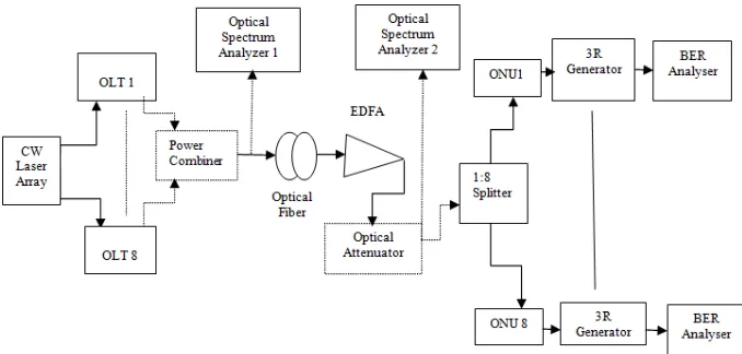
ESCRIPTIONThe simulation model for GPON downstream transmission is proposed using different advanced modulation formats system i.e. carrier suppressed return to zero (CSRZ), duobinary return to zero (DRZ) and modified return to zero (MDRZ) to evaluate system performance .Figure 1 depicts the block diagram for simulation setup for GPON system architecture. The Continuous Wave (CW) laser array with 8 ports operates at frequency 193.1 THz which inputs light signal to Optical Line Terminal (OLT) unit with variable input power (0 to 20 dBm).
Figure 1 Block Diagram for Simulation Setup for 8 users GPON Architecture.
The transmission section of GPON system contains optical line terminal (OLT) unit in which three advanced modulation formats i.e. CSRZ, MDRZ and DRZ are used. The structure of the optical line terminal unit varies according to each modulation format. Figure 2 shows the architecture of OLT unit for CSRZ modulation format in which PRBS Generator which is directly fed to the NRZ Pulse Generator, now the output of the NRZ Pulse Generator goes to the modulator type Mach Zehnder which takes input light signal from CW Laser Array. The modulated signal from modulator goes to another Mach Zehnder modulator which also takes input from Sine Generator having frequency 20 GHz and phase 0 degree.
Volume 3, Issue 4, April 2014
Page 337
Figure 4 OLT Components for DRZ Format.
The output from each OLT unit inputs to 1:8 power combiner through which light signal transfers over optical fiber channel. The light signal travelled over single mode optical fiber which is further amplified through Erbium Doped Fiber Amplifier (EDFA). The EDFA magnifies the signal in the optical link which tends to decrease BER. The magnified signal output from EDFA goes to optical attenuator which forwards the signal to optical splitter which splits the input into the 1:8 outputs, now the 8 outputs of the filter is fed to the receiver side of users. The optical spectrum analyzers are attached to optical link which is used to track and observe the spectral characteristics of various locations. Power Splitter is used to direct the signal to each of 8 ONU’s, followed by 3R regenerator, which is used to regenerate the electrical signal. Each 3R regenerator is further directly connected to BER analyzer, which is used to obtain the graphs and to measure the performance of eye diagram, Min BER, Q-value and Eye Height.
Figure 5 ONU Components for GPON Architecture.
Figure 5 shows the components in Optical Network Unit (ONU) of GPON system. Each ONU takes input from power splitter. Each ONU consists of an optical attenuator; Bessel optical filter, PIN photoelectric detector and low pass Bessel filter. The Bessel optical filter is used to filter the signal by using Bessel frequency transfer function. The photoelectric detector is used to convert optical signal into electrical signal which pass through low pass Bessel filter and 3R generator. PIN photo detector detects the electrical signal at receiver side for optical error correction. By using 3R generator, it is possible to recover the original bit sequence and electrical signal.
4.
R
ESULTSA
NDD
ISCUSSIONSThe GPON simulation model for downstream transmission is firstly implemented using Non Return To Zero (NRZ) modulation format which results Q factor 18.33 and min BER e-75 at 20 km length of fiber [9]. An eye diagram is shown in figure 6 for NRZ format at distance 43 km with Q factor 6.71 and min BER 8.40 e-012 at power 5 dBm.
Figure 6 Eye Diagram for NRZ Modulation Format at 43 km
Fork 1*2
Subtractor
Duobinary Precoder PRBS
Generator
LiNb MZ Mod LiNB MZ
Mod1 Sine Gen Phase = -90 Freq = 40 GHz
Input from CW Laser Array
NRZ Gen T
Optical Attenuator
Splitter 1:8
Low Pass Bessel Filter Bessel Optical
Filter
Volume 3, Issue 4, April 2014
Page 338
Then the proposed methodology of GPON architecture is simulated for advanced modulation such as CSRZ, MDRZ and DRZ by varying input power from 0 to 20 dBm. An EDFA amplifier is used in the transmitter to boost the optical signal to the desired power level. The figure 7 (a), (b) and (c) shows eye diagrams for CSRZ format in GPON system at varying power 5 dBm, 10 dBm and 20 dBm respectively at constant bit rate 2 Gbps. The maximum distance covered by GPON system is up to 240 km at power 20 dBm in case of CSRZ modulation format.Figure 7 Eye Diagrams for CSRZ at Pin (a) 5dBm (b) 10 dBm (c) 20 dBm at distance 170 km, 190 km and 240 km respectively.
The figure 8 (a), (b) and (c) depicts eye diagrams for MDRZ modulation format at power 5 dBm, 10 dBm and 20 dBm respectively at constant bit rate 2 Gbps. The maximum transmission distance covered by GPON system in case of MDRZ modulation format is up to 230 km at power 20 dBm and bit rate 2 Gbps.
Figure 8 Eye Diagram for MDRZ at Pin (a) 5 dBm (b) 10 dBm (c) 20 dBm at distance 160 km, 180 km and 230 km respectively.
The performance of GPON system in case of DRZ modulation format is shown in figure 9. The figure 9 (a), (b) and (c) shows diagrams for DRZ modulation format at power 5 dBm, 10 dBm and 20 dBm respectively at constant bit rate 2 Gbps. The maximum distance covered by GPON system in case of DRZ modulation format is up to 240 km at power 20 dBm and bit rate 2 Gbps.
Volume 3, Issue 4, April 2014
Page 339
So the above analysis demonstrates that the GPON system covers maximum distances by using three advanced modulation formats CSRZ, MDRZ and DRZ with EDFA for downstream transmission. The simulation setup is analyzed at three different powers i.e. 5 dBm, 10 dBm and 20 dBm on 2 Gbps bit rate. The maximum distance is covered using three modulation formats at power 20 dBm in GPON system architecture.5.
C
ONCLUSIONThis paper has simulated the Gigabit Passive Optical Network (GPON) access network architecture which provides a reliable long reach last mile connection with high bandwidth to provide fast broadband internet access to residential and business customers. In this implementation, the GPON system architecture is simulated having 8 subscribers using three advanced modulation formats with variable input power and constant bit rate. The simulative analysis has shown that CSRZ, MDRZ and DRZ modulation formats with an Erbium Doped Fiber Amplifier (EDFA) maximizes the transmission distance up to 240 km at power 20 dBm and bit rate 2 Gbps. Thus GPON is regarded as one of the best choices for broadband access network in the future.
References
[1] W. Zhaoqing, “Research on the Application of GPON Technologies,” In Proceedings of IEEE International Conference on Multimedia and Signal Processing, pp. 61-63, 2011.
[2] Hazra, V. Manasa, P. Singla, “Performance Analysis of 1.25 Gbps Downstream transmission of GPON FTTX,” International Journal of Scientific & Engineering Research, Volume 4, Issue 3, 2013.
[3] Kochera, R.S. Kalera, R. Randhawa, “Simulation of fiber to the home triple play services at 2 Gbit/s using GE-PON architecture for 56 ONUs,” Optik 124, pp. 5007-5010, 2013.
[4] B. Zhu, D. Au, F. Khan, Y. Li, “1:n 10G-PON Overlay of GPON link using Bidirectional Raman Amplifier,” In Proceedings of IEEE Optical Comunications, 38th European Conference and Exhibition, 2012.
[5] Nesset, K. Farrow, P. Wright, “Bidirectional, Raman Extended GPON with 50 km Reach and 1:64 Split Using Wavelength Stabilised Pumps,” In Proceedings of IEEE Optical Communications, 37th European Conference and Exhibition, 2011.
[6] B. Zhu, D. Au, F. Khan, Y. Li, “Coexistence of 10G-PON and GPON Reach Extension to 50-km with Entirely Passive Fiber Plant,” In Proceedings of IEEE Optical Communications, 37th European Conference and Exhibition, 2011.
[7] N. Kumar, “Improved performance analysis of Gigabit passive optical networks,” Optik 125, pp. 1837– 1840, 2014.
[8] A. Kaur, M.L.Singh, AnuSheetal, “Comparison ofRZ and NRZ Data Formats for CoExisting GPON and XG-PON System,” In Proceedings of the International Conference on Advanced Nanomaterials & Emerging Engineering Technologies, pp. 666-669, 2013.
[9] V. Shrivastav, M. Tiwari, J. K.Singh, S. Rathor, “Simulation of 2Gb/s Downstream Transmission Performance of GPON,” International Journal of Advanced Technology & Engineering Research, Volume 2, Issue 6, pp. 64-68, 2012.
[10]E. R. de Paiva, M. M. Freire, U. R. Duarte, A. B. Sassi, A. C. Bizetti, J. F. Pozzuto, J. B. Rosolem, M. A. Romero,” 80 km Extended Gigabit Passive Optical Network,” In Proceedings of IEEE Microwave & Optoelectronics Conference, 2011.
AUTHOR
Gayatri has finished the diploma in Computer Engineering from Punjab Technical Board of Institute & Training and B.E. degree in Computer Science and Engineering from Punjab University in 2009 and 2012, respectively. She is now pursuing M.Tech in Computer Science and Engineering (Networking Systems) from Ambika Paul Institute of Technology, Punjab Technical University Main Campus, Kapurthala, Punjab, India
Malti Rani received B.Tech and M.Tech degrees in Department of Computer Science from Ludhiana College of Engineering and Sri Sai Institute of Technology in 2008 and 2011, respectively. She is now working as Assistant Professor in Computer Science Department at Ambika Paul Institute of Technology, Punjab Technical Technical University Main Campus, Karpurthala, Punjab, India.
Teaching experience: 4 years.
Area of Interest: Optical networks and Wireless Networks. Total number of Publications: 8