107
Copyright © 2011-15. Vandana Publications. All Rights Reserved.
Volume-5, Issue-2, April-2015
International Journal of Engineering and Management Research
Page Number: 107-111
Less Complex and Memory Efficient Multiple Descriptive Coding for
Image Transmission over Wireless Sensor Networks
Santosh Kr. Mishra1, Mohd. Javed Khan2, Saif Ahmad3, Dr. Rabindra Kumar Singh4
1,2,3
Department of Electronics & Communication Engineering, Integral University, Lucknow, Uttar Pradesh, INDIA
4
Department of Electronics Engineering, KNIT, Sultanpur, Uttar Pradesh, INDIA
ABSTRACT
In this paper a new design approach for embedded block coder for image is proposed .The proposed method is based on the set portioning embedded block coder (SPECK) algorithm, which is highly flexible and its compression efficiency quite competitive with other coders. In this method MDC algorithm based on SPECK having memory efficient and less complex are presented, suitable for real-time applications of image communication over wireless channels. Multiple Description Coding (MDC) is one of the promising solutions for the image delivery over lossy networks. In the MDC the reconstructed quality of image will be improved as long as more descriptions are received ,since in this method the lost description can be estimated at receiver In the original SPECK coder algorithm large dynamic memory is required (i.e. for link lists), which is not suitable for memory constrained portable devices. The proposed algorithm does not require any dynamic memory, which also reduces access time and complexity of coding /decoding.
Keywords— MDC, Poly-phase Sampling, SPECK,
Wavelet Transform.
.
I.
INTRODUCTION
Since the communication systems are design for information interchange reliably. Due to packet loss and channel failures in the wireless communication systems, the reliable communication is a proven challenge. The reliability of the communication system can be achieved effectively by using Multiple Descriptive (MD) coding scheme. In this method more than one equally important descriptions of source are produced and simultaneously transmitted over different channels, so that various reconstruction qualities are obtained from different descriptions (subsets) [1,2,3,4].The MDC methods which are in use, can be divided broadly in two categories,
Bandwidth-Efficient and Non-Bandwidth-Efficient methods [5].In Bandwidth-efficient MD encoders the inherent redundancy of the signal is used to estimate to lost description and no extra redundancy bits between descriptions are introduced. Here the different descriptions are created by dividing the domain of the signal before or after the transformation [5].While, The controlled extra redundancy (redundancy which is not inherent in the signal, but added to it) between descriptions are introduced. The different ways can be used for adding extra redundancy in non-bandwidth-efficient encoders: through overlapping side quantizers (MDSQ) [6], frame expansions [3], correlating transforms [1] or forward error correction (FEC) [7]. Since the non-bandwidth-efficient MD encoders typically need more bandwidth and computational power than the bandwidth-efficient MD encoders.
The bandwidth-efficient encoders are more suitable for error prone wireless channels and also for mobile terminals having less computational power. So the low complexity and high efficient can be an appropriate approach for implementing MD coders in wireless applications.
108
Copyright © 2011-15. Vandana Publications. All Rights Reserved.
II.
RELATED WORK
2.1. Multiple description coding
In the MDC two or more descriptions are generated by dividing the source image into correlated bit streams. The bit streams are independently decodable and also mutually refinable. These descriptions are then transmitted separately, through different network paths. Here the MD image coding is promising in wireless (error prone channel) transmission, since there are correlations between the received and lost descriptions, so the lost description can be estimated at receiver. So, as long as one or more descriptions arrive at the receiver acceptable quality can be reconstructed. The higher quality of the image can be achieved as long as more descriptions are received. A MDC scheme does not require retransmission when package losses occur unless the losing rate is extremely high. That is why the MDC is so popular. Usually MDC is used for two applications: .real time communications and reducing the complex of network design. For real time communications, such as video phone or video conference, retransmission is not allowed in those applications. MDC doesn’t need feedback and retransmission, and all the packages are equal.
Figure 1 shows the performance of MDC and other coding methods under the same losing rate. It is obvious that the MDC method performs much better than layered and non-layered coding methods
The MDC coders are mainly focus on the multiple description quantizers and transformations [8-10]. Here the some residual information is added in the source coding and by which better reconstruction is achieved in noisy transmission. But there are some limits due to their low capability in combining with the standard image coding technology.
Figure 1: Comparisons of MDC and other coding methods [11]
The practical design issue in MDC is how to introduce the redundancy in controlled amount into the different descriptions, so that the decoder can utilize it conveniently.There are so many methods are proposed to
generate multiple description coding for transmission of images over wireless channels. In [11],by using a central quantizer and an index assignment a multiple description scalar quantizer (MDSQ) is developed, which generates two side quantizers such that each of them alone produces an acceptable side distortion, whereas their combination yields the finer central quantizer. The MDSQ is asymptotically near optimal [12], and has been employed in e.g., [13] and [2], after the DCT or wavelet transform. However, the MDSQ index assignment is difficult to design and implement, and its redundancy is not easy to adjust.
In [14], a modified MDSQ (MMDSQ) with the same asymptotical performance as the MDSQ is developed, in which two staggered scalar quantizers are used to generate the first layer of each description. Another scalar quantizer is used to further partition the joint bins of the first-layer quantizers, and its output is split into the two descriptions. The MMDSQ avoids the index assignment and can easily adjust the redundancy. It also outperforms other MDSQ-based methods in MD image coding. However, both MDSQ and MMDSQ do not perform well at low redundancy regime, which is a desired property of good MDC schemes [1].
Another family of MDC schemes is based on the source splitting approach pioneered by Jayant in, where a signal is split into even and odd samples, and DPCM is used to encoded each description. If one description is lost, the missing data are predicted from their neighbors in the other description, using the source correlation. However, the prediction errors of the missing data are tied to the source correlation, which cannot be controlled. In DPCM is used before splitting, and the prediction in the DPCM is designed to preserve some source correlations. Therefore, the redundancy between the descriptions can be adjusted to some extent. Although the method reduces the inter description prediction error, the remaining error still limits the side decoder performance, especially at high rates.
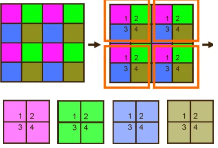
2.2 Poly Phase Sampling
109
Copyright © 2011-15. Vandana Publications. All Rights Reserved.
Figure 2: Four pictures after poly-phase sampling
2.3 The merging and splitting of bit streams
In order to achieve any numbers of descriptions at will and to transfer via multiple channels, a bit stream merging and splitting method is proposed in the paper. The technique contains two processes: merging process in encoding side and splitting process in the decoding side. The details are shown in Figure 3.
Figure 3(a): The combination of two descriptions
Figure 3 (b): The combination of three descriptions
2.4. Reconstruction
Reconstruction is the last step of decoding side to fill up the losing pixels caused by package losses. Take Figure 4 as an example, assume that the brown pixel is the losing pixel. Reconstruction is obtained by taking average of 3above pixels and filling in the losing pixel. This is a simple but an effective method.
Figure 4: Reconstruction block diagram
III.
LINEAR INDEXING
A single number is used to represent the index of a coefficient instead of two in the linear indexing [2]. Let R = C = 2N be the number of rows and columns of the square image, and let r and c be zero-based row and column indices. Represent the row index in binary as, r = [rLr−1, . . . , r1, r0], where each of the rnis a bit, and for the column
index as c = [cLr−1, . . . , c1, c0].The linear index is defined
by i = [rLr−1, cLr−1, . . . , r1, c1, r0, c0
+
+
∈
∈
=
mSubject
to
i
mI
&
m
I
4
],
4
max[
ε
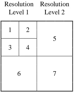
]for an index (r, c) . The bits of r and c are simply interleaved. The linear index I ranges from 0 to I −1, where I = RC. The linear indexing property can be used in the tree based block coders for coefficient positioning as. The first index i and set length will specify the number of coefficients of the set, where the i and £ are the first index and set length respectively for a square set. The size of the set is also embedded in first index of the set to be processed in the SPECK. The set length is given by the highest integer power of 4 by which first index i of the set is completely divisible as given in the equation (1).So the SPECK algorithm can be implemented without use of list or markers Illustration of the linear indexing for an 8X8 image with 2-level DWT (discrete wavelet transform) as given in Figure 5.
I+
0 1 2 3 4 5 6 7
0 0 1 4 5 16 17 20 21
1 2 3 6 7 18 19 22 23
2 8 9 12 13 24 25 28 29
3 10 11 14 15 26 27 30 31
4 32 33 36 37 48 49 52 53
5 34 35 38 39 50 51 54 55
6 40 41 44 45 56 57 60 61
7 42 43 46 47 58 59 62 63
110
Copyright © 2011-15. Vandana Publications. All Rights Reserved.
Resolution Resolution
Level 1 Level 2
1 2
5
3 4
6 7
(b)Sub bands at different resolution levels
Sub band 1 2 3 4 5 6 7
Linear Index Range 0 to 3 4 to 7 8 to 11 12 to 15 16 to 31 32 to 47 48 to 63
Set length 4 4 4 4 16 16 16
(c) Linear indexing of each sub band and size.
Figure 5: Illustration of linear indexing for an 8x8 image with 2-level DWT
IV.
PROPOSED MD IMAGE
ALGORITHM
The proposed algorithm is a novel implementation of MDC based on SPECK Block Coder for Image communication over wireless channels for real time application. Since MDC is useful for the real time applications like video conferencing where the re-transmission is not allowed. Due to rapid growth in handheld/portable devices in present scenario a lot of data, we have to transmit over wireless channels where retransmission is not allowed (e.g. video conferencing). But dynamic memory, battery power and processing power are the main constrain for the hand held /portable devices. So the original SPECK with the MDC based image coding for the real time applications will not be suitable for the Image/video communication between portable / hand held devices. In our proposed algorithm the MD image/Video coding will be advantageous for real time communications and listless SPECK will not only reduce the memory requirement (since here SPECK is implemented without use of list or markers) but also less complex and requiring less time for processing.
V.
CONCLUSIONS
Since my approach is to develop an efficient method to transmit images/videos between hand held/portable multimedia devices through error prone wireless channels for that I have used MDC to overcome the problem of packet loss due to congestion in traffic or due to the erroneous environment of wireless channels. But I have to constrained with hand held/portable multimedia devices like processing power , power backup and memory capacity problem. So to save the memory linear indexing method based SPECK coder must be implemented which does not require running memory that is more suitable for my applications.
REFERENCES
[1] Y. Wang, M.T. Orchard, V.A. Vaishampayan, A.R. Reibman, “Multiple Description Coding Using Pairwise Correlating Transforms”, IEEE Trans. Image Processing, Vol. 10, No. 3, March 2001.
[2] S. D. Servetto, K. Ramchandran, V.A Vaishampayan, “Multiple Description Wavelet Based Image Coding”, IEEE Trans. Image Processing, Vol. 9, No. 5, May 2000. [3] V. K. Goyal, J. Kovacevic, “Generalized Multiple Description Coding With Correlating Transforms”, IEEE Trans. Information Theory, Vol. 47, No. 6, September 2001.
[4] V. K. Goyal, “Multiple Description Coding: Compression Meets the Network”, IEEE Signal Processing Magazine, September 2001.
[5] I. V. Bajic, J.W. Woods, “Domain Based Multiple Description Coding of Image and Video”, IEEE Trans. Image Processing, Vol. 12, No. 10, Sep 2003.
[6] V.A. Vaishampayan, “Design of Multiple Description Scalar Quantizers, IEEE Trans. Information Theory, Vol. 39, pp. 821-834, May 1993.
[7] R. Puri, K. Ramchandran, “Multiple Description Source Codingusing Forward Error Correction Codes”, in Proc. 33rdAsilomarConf on Signal, Systems, and Computers, Pacific Grove, CA, Oct 1999.
[8] S. Shirani, M. Gallant, and F. Kossentini, "Multipledescription image coding using pre- and post-processing",IEEE International Conference on Information Technology,2001, Las Vegas, NV, USA, pp. 35-39.
[9] L.Wang, M.N.S. Swamy, M.O Ahmad,
111
Copyright © 2011-15. Vandana Publications. All Rights Reserved.
[11] V. A. Vaishampayan, “Design of multiple description scalar quantizers,”IEEE Trans. Inf. Theory, vol. 39, no. 3, pp. 821–834, May1993.
[12] V. A. Vaishampayan and J.-C.Batllo, “Asymptotic analysis of multiple description quantizers,” IEEE Trans. Inf. Theory, vol. 44, no. 1, pp.278–284, Jan. 1998.
[13] J.-C. Batllo and V. A. Vaishampayan, “Asymptotic performance of multiple description transform codes,” IEEE Trans. Inf. Theory, vol. 43, no. 2, pp. 703–707, Mar. 1997.
![Figure 1: Comparisons of MDC and other coding methods [11]](https://thumb-us.123doks.com/thumbv2/123dok_us/9775382.1962774/2.612.53.279.513.627/figure-comparisons-mdc-coding-methods.webp)