ORIGINAL ARTICLE
Type Synthesis of 1T2R Parallel Mechanisms
Using Structure Coupling-Reducing Method
Haitao Liu
1*, Ke Xu
1, Huiping Shen
2, Xianlei Shan
1and Tingli Yang
2Abstract
Direct kinematics with analytic solutions is critical to the real-time control of parallel mechanisms. Therefore, the type synthesis of a mechanism having explicit form of forward kinematics has become a topic of interest. Based on this purpose, this paper deals with the type synthesis of 1T2R parallel mechanisms by investigating the topological structure coupling-reducing of the 3UPS&UP parallel mechanism. With the aid of the theory of mechanism topology, the analysis of the topological characteristics of the 3UPS&UP parallel mechanism is presented, which shows that there are highly coupled motions and constraints amongst the limbs of the mechanism. Three methods for structure coupling-reducing of the 3UPS&UP parallel mechanism are proposed, resulting in eight new types of 1T2R parallel mechanisms with one or zero coupling degree. One obtained parallel mechanism is taken as an example to demon-strate that a mechanism with zero coupling degree has an explicit form for forward kinematics. The process of type synthesis is in the order of permutation and combination; therefore, there are no omissions. This method is also appli-cable to other configurations, and novel topological structures having simple forward kinematics can be obtained from an original mechanism via this method.
Keywords: Type synthesis, Structure coupling-reducing, Coupling degree, Parallel mechanism
© The Author(s) 2019. This article is distributed under the terms of the Creative Commons Attribution 4.0 International License (http://creat iveco mmons .org/licen ses/by/4.0/), which permits unrestricted use, distribution, and reproduction in any medium, provided you give appropriate credit to the original author(s) and the source, provide a link to the Creative Commons license, and indicate if changes were made.
1 Introduction
Forward kinematics, which is one of the fundamen-tal issues in the kinematic analysis of a parallel mecha-nism (PM) [1], refers to evaluating the pose of a platform from a set of specified values of actuated joint param-eters. Generally, the forward kinematic analysis of a PM is much more complex than its reverse process, i.e., inverse kinematics. The difficulty is mainly in relation to the dependent motions of the passive joints in the mechanism.
For a better illustration, three planar open kinematic chains that can be employed to compose planar PMs are given as examples (see Figure 1). The first one is a 2-degree-of-freedom (DOF) planar open kinematic chain applying a constraint on a moving platform. It is easy to see that given the position of point A, the lengths of the linkages, and input angle θ, the position of point D on
the moving platform can be directly determined using the vector pointing from point A to point D. Meanwhile, for the second and third cases, because of the need to evaluate passive joint parameters α* and β*, the for-ward kinematics of point D cannot be solved using only the kinematic equations formulated by the open kin-ematic chain itself, and additional equations depicting the coupled motions among the chains of the PM have to be derived. Therefore, the higher the number of pas-sive joints in a PM, the higher the complexity of the for-ward kinematic analysis. In order to calculate the forfor-ward kinematic problem of a PM efficiently, great efforts have been made to develop numerical algorithms for particu-lar case studies [2–8]. Although the real-time perfor-mance benefits of these methods have been exemplified, only approximate solutions for forward kinematics have so far been attained.
Because this issue is critical to the real-time control of PMs [9], the type synthesis of a mechanism having an explicit form for forward kinematics has become a topic of interest. However, the majority of currently known type syntheses aim to realize output motion only [10–12].
Open Access
*Correspondence: [email protected]
1 Key Laboratory of Mechanism Theory and Equipment Design, Ministry of Education, Tianjin University, Tianjin 300350, China
To design PMs with analytic direct kinematics, a metric for assessing the complexity of forward kinematics at a topological level has to first be defined. For this purpose, the motion of coupling degree, which is denoted by κ, is proposed in the theory of mechanism topology [13, 14], giving the minimum number of passive joint parameters that need to be solved in the process of forward kin-ematic analysis. For a specific PM, the value of κ is usu-ally an integral number larger than zero. However, when its value is equal to zero, analytical solutions for forward kinematics can be achieved. Through further examina-tion of the coupling degree of a PM, the approach known as structure coupling-reducing (SCR), which aims to reduce the coupling degree while keeping the DOF and position and orientation characteristics (POC) [14] of the mechanism unchanged, is developed in [15, 16]. In this manner, new topological structures that have simple for-ward kinematics can be obtained from an original mech-anism by rearranging the axes and positions of the joints. With the aid of this approach, eight new 3-DOF transla-tional PMs [17], three types of 3T1R PMs [18], and six-teen novel 6-DOF PMs [19–23] have been synthesized.
Drawing on the SCR method, this paper deals with the type synthesis of 1T2R PMs by reducing the cou-pling degree of the 3UPS&UP PM within the Tricept robot [24–26]. The rest of this paper is organized as fol-lows. In Section 2, the topological characteristics of the 3UPS&UP PM are systemically analyzed, followed by the calculation of the coupling degree of the mechanism. In Section 3, the SCR methods are then introduced to synthesize 1T2R PMs with new topologies. Finally, in Section 4, the forward kinematic analysis of one of the obtained PMs is performed to demonstrate the validity of the method, before conclusions are drawn in Section 5.
2 Topological Characteristics Analysis
In this section, the topological characteristics [13, 14] in terms of the POC set, decomposition of single-open chains (SOC), constraint degree Δ, and coupling degree
κ of the 3UPS&UP PM within the Tricept robot are sys-tematically analyzed.
2.1 Mobility Analysis
As shown in Figure 2, the 3UPS&UP PM consists of three active limbs and one passive limb connecting the base to the moving platform. The active limb i ( i=1, 2, 3 ) is composed of a universal joint Ui, a prismatic joint Pi, and
a spherical joint Si. Meanwhile, the passive limb is
com-posed of a universal joint U4 and a prismatic joint P4. Based on the theory of mechanism topology [14], the POC sets indicating the motion characteristics of the U, P, and S joints (see Figure 3) can be expressed as follows:
where t and r represent translation and rotation, respec-tively; ρUi and ρSi are the vectors from the centers of Ui
and Si to a reference point O, respectively; the superscript
is the number of translational/rotational motion; (*) (1)
MUi =
t2(⊥ρUi)
r2(||Ui)
, MPi=
t1(||Pi)
r0
,
MSi=
t2(⊥ρSi)
r3
,
θ θ θ
A D
A D
A D
B
C
B
α* y
x
β*
α* y
x
y
x
a b c
Figure 1 Open kinematic chains
Figure 2 Schematic diagram of 3UPS&UP PM
describes the direction of translation or the axis of rota-tion; while {*} denotes the parasitic translations induced by rotations. For example, t1(||Pi) and r0 in MPi indicate that a prismatic joint Pi can achieve only one
transla-tional motion parallel to the direction of the joint. The joints are serially connected in a limb, and there-fore, the POC set of a limb can be expressed as the union of the POC sets of all joints. Here, the operation rules of “union” are presented in Refs. [27, 28]. The POC sets of UPS and UP limbs can then be obtained via
In Eq. (2), because the rotational axes of Si could be
par-allel to those of Ui, the union of {t2(⊥ρUi)} and {t2(⊥ρSi)}
leads to t2(⊥ρUi) , according to the rules given in Ref.
[21]. Furthermore, because the directions of t2(⊥ρUi) are perpendicular to the direction of Pi, the union of t2(⊥ρi)
and t1(||Pi) results in t3 . In Eq. (3), the translational directions of {t2(⊥ρU4)} and t1(||P4) are independent;
therefore, the union of these two translational motions is t1(||P4)∪ {t2(⊥ρU4)} . From Eqs. (2) and (3), it can be found that the UPS limb is a 6-DOF unconstrained open (2) Mbi=MUi∪MPi∪MSi
= t
2(⊥ ρUi)
r2(||Ui)
∪
t1(||Pi) r0
∪ t
2(⊥ ρSi)
r3
=
t1(||P
i)
r0
∪
{t2(⊥
ρUi)} ∪ {t2(⊥ρSi)}
r2(||Ui)∪r3
=
t1(||Pi)∪t2(⊥ρUi)
r3
=
t3 r3
, i=1, 2, 3,
(3) Mb4=MU4∪MP4=
{t2(⊥ρU4)}
r2(||U4)
∪
t1(||P4)
r0
=
t1(||P4)∪ {t2(⊥ρU4)} r2(||U4)
.
kinematic chains, while the UP limb has one translational and two rotational independent motions.
Because of the parallel topology of the mechanism, the POC set of the moving platform, Mpa, can be obtained
by taking the intersection of the POC sets of the limbs. Based on the operation rules of “intersection” given in Refs. [27, 28], the POC set is defined as follows:
from which it can be seen that Mpa is identical with Mb4. For this reason, the UP limb is also known as the POC chain [29].
2.2 Coupling Degree
The coupling degree can be considered as a metric for assessing the complexity of forward kinematics. For the evaluation of coupling degree of the PM, the mechanism must be decomposed into several SOCs and independent loops [28]. As shown in Figure 4, the decomposition is given as follows:
The first independent loop, Loop1, can then be defined by fixing both end links of SOC1 according to Ref. [14], while the second independent loop, Loop2, is obtained by taking Loop1 as a sub-mechanism and attaching two end links of SOC2 to Loop1. Analogously, the third independ-ent loop, Loop3, is defined by attaching two end links of SOC3 to Loop2 (see Figure 4). With these definitions, the (4) Mpa=
4 ∩
i=1Mbi
=
t1(||P4)∪ {t2(⊥U4)}
r2(||U4)
∩
t3
r3
∩
t3
r3
∩
t3
r3
=
t1(||P4)∪ {t2(⊥U4)}
r2(||U4)
,
SOC1{U1−P1−S1−P4−U4},
SOC2{U2−P2−S2}, SOC3{U3−P3−S3}.
number of independent displacement equations of the three loops can be computed following the method pre-sented in Ref. [28].
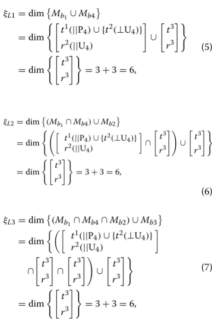
where dim{*} denotes the dimension, i.e., the number of independent motions, of a POC set. Subsequently, to evaluate the coupling degree, the constraint degree describing the constraint relationship of a SOC has to be calculated [14]. For this specific case, the constraint degrees of the three SOCs are
(5) ξL1=dimMb1∪Mb4
=dim
t1(||P4)∪ {t2(⊥U4)}
r2(||U4)
∪
t3
r3
=dim
t3
r3
=3+3=6,
(6) ξL2=dim(Mb1∩Mb4)∪Mb2
=dim
t1(||P
4)∪ {t2(⊥U4)}
r2(||U 4)
∩
t3
r3
∪
t3
r3
=dim
t3
r3
=3+3=6,
(7) ξL3=dim(Mb1 ∩Mb4∩Mb2)∪Mb3
=dim
t1(||P4)∪ {t2(⊥U4)} r2(||U4)
∩
t3
r3
∩
t3
r3
∪
t3
r3
=dim
t3
r3
=3+3=6,
�1= 5
i=1
fi−I1−ξL1 =9−1−6=2,
�2= 3
i=1
fi−I2−ξL2 =6−1−6= −1,
�3= 3
i=1
fi−I3−ξL3 =6−1−6= −1,
where fi is the DOF of the ith joint, and Ij is the number of
actuated joints in the jth SOC ( j=1, 2, 3 ). The constraint
degree of SOC1 is shown to be 2, which means that two passive joint parameters have to be solved to determine the motion of SOC1. Meanwhile, the constraint degree of SOC2 (SOC3) is −1 , indicating that a constraint equation should be established to solve one of the passive joint parameters in the kinematic equations of SOC1. Finally, the coupling degree of the 3UPS&UP PM can be evalu-ated via [14]
This relationship demonstrates that the constraints of the three SOCs are highly coupled. Therefore, there is no analytic solution for the forward kinematics of the 3UPS&UP PM. Approaches for the type synthesis of new topological structures with the same topological charac-teristics but using simple forward kinematics are investi-gated in the following section.
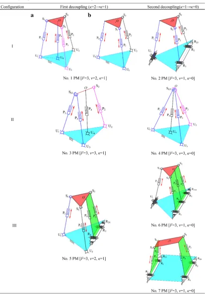
3 Type Synthesis
Three SCR methods, which aim to reduce the coupling degree of the 3UPS&UP PM and obtain new mechanisms that have simple forward kinematics, are presented in this section.
3.1 Method One: Changing the Passive POC Chain into Active Chain
In the 3UPS&UP PM, the UP limb is the POC chain because of Mb4 being identical with Mpa. When the passive
prismatic joint in the POC chain is changed into an active one (see Figure 5), the constraint degree 1 of SOC1 can be reduced to
(8) κ= 1
2 3
j=1 |�j| =
1
2(2+ | −1| + | −1|)=2.
SOC1{U1−P1−S1−P4−U4},
�1=
5
i=1
fi−I1−ξL1 =9−2−6=1,
because I1= 2 in this equation. Furthermore, in order to achieve a PM without redundant actuation, the active joint P3 in SOC3 is taken as a passive joint, resulting in
Hence, the coupling degree of this new PM (No.1 (a) in Table 1) is
indicating that only one passive joint parameter needs to be solved in the forward kinematics. Because limb 3 becomes a 6-DOF passive limb in this special case, it has no effect on Mpa. Therefore, it is removable, leading to
the PM (No.1 (b) in Table 1) within the TriVariant robot [30].
3.2 Method Two: Making the Centers of Spherical Joints Coincident
Another approach to reduce the coupling degree is by making the centers of the spherical joints on the moving platform coincident. For example, the centers of spherical joints S1 and S3 are coincident, as shown in No. 3 in Table 1. The SOCs of the obtained mechanism (see Figure 6) and their constraint degrees can then be redefined as
resulting in the coupling degree of this new mechanism: SOC3{U3−P3−S3},
�3= 3
i=1
fi−I3−ξL3 =6−0−6=0.
(9)
κ= 1
2
3
j=1 |�j| =
1
2(1+ | −1| + |0|)=1,
SOC1{U1−P1−S13−P3−U3},
�1= 5
i=1
fi−I1−ξL1 =9−2−6=1,
SOC2{U4−P4},
�2=
2
i=1
fi−I2−ξL2 =3−3=0,
SOC3{U2−P2−S2},
�3= 3
i=1
fi−I3−ξL3 =6−1−6= −1,
(10) κ= 1
2 3
j=1 |�j| =
1
2(|1| + |0| + | −1|)=1.
Therefore, a new type of 1T2R PM with lower coupling degree is synthesized. In addition, we can also make the centers of three spherical joints connected to the mov-ing platform coincident. In this way, a new mechanism, as shown in No.4 in Table 1, can then be obtained. For this mechanism, the redefined SOCs and their constraint degrees are given as follows:
Here, the spherical joint S2 in SOC3 is degenerated into a revolute joint R(U1-U3) with the rotational axis parallel to the line passing through the centers of joints U1 and U3. The coupling degree of this mechanism is then
Because κ =0 , it can be concluded that the PM has an explicit form for forward kinematics.
3.3 Method Three: Integrating the Rotational Axes of Universal Joints
This method aims to directly reduce
fi in a SOC. Note that the joint U can be decomposed into a proximal rev-olute joint R′ and a distal revolute joint R with their rota-tional axes being perpendicular. Hence, in the 3UPS&UP PM, the revolute joints R′2 and R′4 of U2 and U4, respec-tively, could be made coincident and integrated into a revo-lute joint R24 (see No. 5 in Table 1). The kinematic chains U4P4 and U2P2S2 can then be regarded as a hybrid single-open chain, HSOC1 [15].
The SOCs and corresponding constraint degrees of this mechanism (see Figure 7) can then be defined as
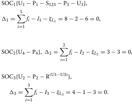
SOC1{U1−P1−S123−P3−U3},
�1= 5
i=1
fi−I1−ξL1 =8−2−6=0,
SOC2{U4−P4}, �2= 2
i=1
fi−I2−ξL2 =3−3=0,
SOC3{U2−P2−R(U1−U3)},
�3= 3
i=1
fi−I3−ξL3 =4−1−3=0.
(11)
κ= 1
2
3
j=1 |�j| =
1
2(|0| + |0| + |0|)=0.
HSOC1{R24−(R2⊥P2−S2) (R4⊥P4)}.
SOC1{HSOC1−S3−P3−U3},
�1=
5
i=1
Consequently, the coupling degree of the new PM is
Furthermore, R′2, R′3, and R′4 of U2, U3, and U4, respec-tively, can also be integrated into one revolute joint R234. In this manner, the kinematic chains U4P4, U3P3S3, and U2P2S2 are converted into another HSOC1,
resulting in the R(2RPS&RP)&UPS PM (No.6 in Table 1) within the TriMule robot [31]. For this mechanism, its SOC can be expressed as
SOC2{U1−P1−S1},
�2=
2
i=1
fi−I2−ξL2 =6−1−6= −1.
(12) κ= 1
2 2
j=1
|�j| = 1
2(|1| + | −1|)=1.
HSOC1{R234−(R4⊥P4)(R2⊥P2−S2)(R3⊥P3−S3)},
SOC1{HSOC1−S1−P1−U1},
�1=
5
i=1
fi−I1−ξL1 =9−3−6=0.
Because there is only one SOC, the coupling degree of this PM is zero. Moreover, if the revolute joints R′1 and R′3 of U1 and U3, respectively, and the revolute joints R′2 and R′4 of U2 and U4, respectively, are made coincident and integrated into revolute joints R13 and R24, respec-tively, a new mechanism No.7 in Table 1 can be obtained. For this case, the kinematic chains U1P1S1 and U3P3S3, and U2P2S2 and U4P4 are converted into HSOC1 and HSOC2, respectively.
The SOC of the obtained PM can be expressed as
This mechanism also has only one SOC, and its cou-pling degree is zero. Besides, if the revolute joints R′2
and R′3 of U2 and U3, respectively, in the PM No. 1(b) in Table 1 are integrated into one revolute joint R23, another new mechanism is obtained, as shown in No. 2 in Table 1.
HSOC1{R13−(R1⊥P1−S1) (R3⊥P3−S3)},
HSOC2{R24−(R2⊥P2−S2) (R4⊥P4)}.
SOC1{HSOC1−HSOC2},
�1=
5
i=1
fi−I1−ξL1 =9−3−6=0. Figure 6 Topological decomposition of No. 3 PM
In this way, the kinematic chains U2P2S2 and U3P3S3 are converted into HSOC1:
The SOC and corresponding constraint degree can be expressed as
It can be proved that the coupling degree of this PM is also zero.
4 Example
In this section, the forward kinematic analysis of the obtained R(2RPS&RP)&UPS PM is given as an example to verify that a PM with κ =0 has an explicit form for forward kinematics, which would illustrate the feasibility of the proposed type-synthesis method.
4.1 Coordinate System
The schematic diagram of the R(2RPS&RP)&UPS PM is shown in Figure 8, where points B, B1, B2, and B3 are the centers of joints R4, U1, R2, and R3, respectively. Point O is the intersection of the axial axis of the passive limb R4P4 and its normal plane in which all centers of S joints, points A1, A2, and A3, are placed. A reference frame B-XYZ is attached to point B, satisfying Y⊥B2B3 and Z⊥△B1B2B3, while a body-fixed frame O-xyz is established at point O, satisfying y⊥A2A3 and z⊥△A1A2A3. The orientation of O-xyz with respect to B-XYZ can then be evaluated via
where c and s represent “cos” and “sin”, respectively.
4.2 Forward Kinematics
When point O is taken as the reference point, its position vector evaluated in B-XYZ can be expressed as
where qi is the length, and si is the unit vector along the axial axis of limb I ( i=1, 2, 3, 4 ); ai=Rai0 ; ai0 and bi are the positioning vectors of Ai and Bi ( i=1, 2, 3 ),
respec-tively, measured in O-xyz and B-XYZ, respectively. Not-ing that
HSOC1{R23−(R2⊥P2−S2) (R3⊥P3−S3)}.
SOC1{HSOC1−P1−U1},
�1= 5
i=1
fi−I1−ξL1 =9−3−6=0.
(13) R=Rot(X,θ1)Rot
�
y,θ2 �
=
cθ2 0 sθ2
sθ1sθ2 cθ1 −sθ1cθ2 −cθ1sθ2 sθ1 cθ1cθ2
,
(14)
q4s4=bi+qisi−ai, i=1, 2, 3,
(15)
s4=R
0 0 1T
=sθ2 −sθ1cθ2 cθ1cθ2 T
and taking norms on both sides of rearranged Eq. (14) leads to
Expanding Eq. (16) then gives the following kinematic equations:
where ai= �ai� and bi= �bi� ( i=1, 2, 3 ), satisfying a2=a3 and b2=b3 . Combining Eq. (18) with Eq. (19) results in
Considering that s2θ
2+c2θ2=1, we can get
When Eq. (21) is solved, the following equations can be obtained:
(16) qi= �q4s4+ai−bi�, i=1, 2, 3.
(17)
a21+b 2 1+q
2
0−2a1b1cθ1−2b1q0sθ1cθ2−q21=0,
(18)
a22+b 2 2+q
2
0−2a2b2cθ2−2b2q0sθ2−q22=0,
(19)
a22+b 2 2+q
2
0−2a2b2cθ2+2b2q0sθ2−q32=0,
(20)
cθ2= 2
�
a22+b 2 2+q
2 0 �
−q22−q 2 3 4a2b2 ,
sθ2= q
2 3−q
2 2 4b2q0.
(21)
q20
3 +P1
q20
2
+P2q20+P3=0,
P1=2a22+2b 2
2−q
2
2−q
2 3,
P2=P12
4−4a22b 2
2, P3=a22
q23−q 2 2
2
4.
(22)
q0=
3
C1+ 3
C2−P13,
A2 A1 A3 B2 B B3 B1 O Y X Z z y x U1 R3 R4 R2 S1 S2 S3 P1 P2 P3 P4 R234 b1 q1s1
a1
q4s4
θ1
θ2
Substituting Eq. (22) into Eq. (20) then leads to
Therefore, the R(2RPS&RP)&UPS PM is proven to have an explicit form for forward kinematics.
5 Conclusions
Investigation on the type synthesis of 1T2R PMs using the method of structure coupling-reducing is presented in this paper. The following conclusions are drawn.
(1) Conducting a topological characteristics analysis of the 3UPS&UP PM shows that the motions of the three SOCs of the mechanism are highly coupled. Therefore, for this setup, explicit solutions for for-ward kinematics cannot be achieved.
(2) Aiming at reducing the coupling degree of the 3UPS&UP PM and synthesizing new mechanisms that have simple forward kinematics, three differ-ent methods are proposed, by which eight new PMs having lower coupling degrees are obtained.
(3) The forward kinematic analysis of the R(2RPS& RP)&UPS PM is presented. The analysis verifies that the obtained new mechanism, which has a zero coupling degree, uses an explicit form for forward kinematics.
Authors’ Contributions
HL was in charge of the whole trial; KX wrote the manuscript; XS assisted with the process of analysis; TY and HS provided the assistance of theory. All authors read and approved the final manuscript.
C1= −D2
2 +
D2
2 2
+
D1
3 3
,
C2= −D2
2 −
D2
2 2
+
D1
3 3
,
D1=P2−P12
3, D2=P3+2P31
27−P1P2 3.
(23) θ2= arcsinq
2 3−q
2 2 4b2q0 ,
(24) θ1=2 arctan
−P4−
� P42−P
2 6+P
2 5
P6−P5
,
P4= −2b1q0cθ2, P5= −2a1b1, P6=a21+b 2 1+q
2 0−q
2 1.
Authors’ Information
Haitao Liu, born in 1981, is currently a professor at Tianjin University, China. He received his PhD degree from Tianjin University, China, in 2010. His research interests include hybrid robot and intelligent robotics.
Ke Xu, born in 1992, is currently a PhD candidate at Key Laboratory of Mechanism Theory and Equipment Design, Ministry of Education, Tianjin Univer-sity, China. He received his master degree on mechanical design and theory from Changzhou University, China, in 2018.
Huiping Shen, born in 1965, is currently a professor at School of Mechanical Engineering, Changzhou University, China. His research interests include parallel mechanism and mechatronics.
Xianlei Shan, born in 1987, is currently a postdoctor at Key Laboratory of Mechanism Theory and Equipment Design, Ministry of Education, Tianjin Univer-sity, China.
Tingli Yang, born in 1940, is currently a distinguished professor at Chang-zhou University, China.
Competing Interests
The authors declare that they have no competing interests.
Funding
Supported by National Key R&D program of China (Grant No.
2017YFB1301800), National Natural Science Foundation of China (Grant No. 51622508), and National Defense Basic Scientific Research program of China (Grant No. JCKY2017203B066).
Author Details
1 Key Laboratory of Mechanism Theory and Equipment Design, Ministry of Education, Tianjin University, Tianjin 300350, China. 2 School of Mechanical Engineering, Changzhou University, Changzhou 213164, China.
Received: 17 January 2019 Revised: 5 September 2019 Accepted: 18 October 2019
References
[1] Z Huang, Y S Zhao, T S Zhao. Advanced spatial mechanism. Higher Educa-tion Press, 2014.
[2] X L Yang, H T Wu, Y Li, et al. A dual quaternion solution to the forward kinematics of a class of six-DOF parallel robots with full or reductant actuation. Mechanism and Machine Theory, 2017, 107: 27-36. [3] W Zhou, W Chen, H Liu, et al. A new forward kinematic algorithm for
a general Stewart platform. Mechanism and Machine Theory, 2015, 87: 177-190.
[4] J S Kim, Y H Jeong, J H Park. A geometric approach for forward kinematics analysis of a 3-SPS/S redundant motion manipulator with an extra sensor using conformal geometric algebra. Meccanica, 2016, 51(10): 2289-2304. [5] X Wu, Z Xie. Forward kinematics analysis of a novel 3-DOF parallel
manipulator. Scientia Iranica, 2019, 26(1): 346-357.
[6] R R Serrezuela, M Á T Cardozo, D L Ardila, et al. A consistent methodology for the development of inverse and direct kinematics of robust industrial robots. ARPN Journal of Engineering and Applied Sciences, 2018, 13(01): 293-301.
[7] W Li, J Angeles. A novel three-loop parallel robot with full mobility: kinematics, singularity, workspace, and dexterity analysis. Journal of Mechanisms and Robotics, 2017, 9(5): 051003.
[8] J P Merlet. A generic numerical continuation scheme for solving the direct kinematics of cable-driven parallel robot with deformable cables. 2016 IEEE/RSJ International Conference on Intelligent Robots and Systems (IROS), 2016: 4337-4343.
[10] S Yang, T Sun, T Huang. Type synthesis of parallel mechanisms having 3T1R motion with variable rotational axis. Mechanism and Machine Theory, 2017, 109: 220-230.
[11] Y Xu, D Zhang, J Yao, et al. Type synthesis of the 2R1T parallel mechanism with two continuous rotational axes and study on the principle of its motion decoupling. Mechanism and Machine Theory, 2017, 108: 27-40. [12] Y Song, P Han, P Wang. Type synthesis of 1T2R and 2R1T parallel
mecha-nisms employing conformal geometric algebra. Mechanism and Machine Theory, 2018, 121: 475-486.
[13] T L Yang, A X Liu, Y F Luo, et al. Theory and application of robot mechanism topology. Beijing: Science Press, 2012. (in Chinese)
[14] T L Yang, A X Liu, H P Shen, et al. Topology design of robot mechanisms. Springer, Singapore, 2018.
[15] H P Shen, L J Yang, X R Zhu, et al. A Method for structure coupling-reducing of parallel mechanisms. The 2015 International Conference on Intelligent Robotics and Applications, Portsmouth, UK, August 24–27, 2015. [16] H P Shen, X R Zhu, H B Yin, et al. Principle and design method for
struc-ture coupling-reducing of parallel mechanisms. Journal of Mechanical Engineering, 2016, 47(8): 388–398. (in Chinese)
[17] H P Shen, L Z Ma, T L Yang. Kinematic structural synthesis of 3-transla-tional weakly-coupled parallel mechanisms based on hybrid chains. Mechanism and Machine Theory, 2005, 41(4): 22-27.
[18] H P Shen, H C Qiang, Q F Zeng, et al. Topological design for a class of novel 3T1R parallel mechanisms with low coupling degree based on coupling-reducing. China Mechanical Engineering, 2017, 28(10): 1163-1171. (in Chinese)
[19] H P Shen, T L Yang, L Z Ma. Methodology for type synthesis of kinematic structures of 6-DOF weakly-coupling parallel mechanisms. Journal of Mechanical Engineering, 2004, 40(7): 14-19. (in Chinese)
[20] H P Shen, T L Yang, L Z Ma. Synthesis and structure analysis of kinematic structures of 6-dof parallel robotic mechanisms. Mechanism and Machine Theory, 2005, 40(10): 1164-1180.
[21] T Z Yu, H P Shen, J M Deng, et al. An easily manufactured structure and its analytic solutions for forward and inverse position of 1-2-3-SPS type
6-DOF basic parallel mechanism. The 2012 IEEE International Conference on Robotics and Biomimetic, December, 11-14, Guangzhou, 2012.
[22] Z Wang, H P Shen, J M Deng, et al. An easily manufactured 6-DOF 3-1-1-1 SPS type parallel mechanism and its forward kinematics. The 2nd IFToMM Symposium on Mechanism Design for Robotics, October, 12-14, Beijing, 2012.
[23] H P Shen, H B Yin, Z Wang, et al. Research on forward position solutions for 6-SPS parallel mechanisms based on topology structure analysis. Journal of Mechanical Engineering, 2013, 49(21): 70-80. (in Chinese) [24] S A Joshi, L W Tsai. The kinematics of a class of 3-DOF, 4-legged parallel
manipulators. ASME Journal of Mechanical Design, 2003, 125: 52-60. [25] B Siciliano. The Tricept robot: inverse kinematics, manipulability analysis
and closed-loop direct kinematics algorithm. Robotica, 1999, 17(4): 437-455.
[26] S Fan, S Fan, X Zhang. A hybrid optimization method of dimensions for the Tricept parallel robot. International Conference on Mechanical Design, 2017: 1343-1364.
[27] T L Yang, A X Liu, Y F Luo, et al. Position and orientation characteris-tic equation for topological design of robot mechanisms. Journal of Mechanical Design, 2009, 131(2): 021001.
[28] T L Yang, A X Liu, H P Shen, et al. On the correctness and strictness of the POC equation for topological structure design of robot mechanisms. Journal of Mechanisms and Robotics, 2013, 5(2): 021009.
[29] T L Yang, A X Liu, H P Shen, et al. Composition principle based on Single-Open-Chain unit for general spatial mechanisms and its application. Journal of Mechanisms and Robotics, 2018, 10(5): 051005.
[30] T Huang, M Li, X M Zhao, et al. Conceptual design and dimensional syn-thesis for a 3-DOF module of TriVariant—a novel 5-DOF reconfigurable hybrid robot. IEEE Transactions on Robotics, 2005, 21(3): 449-456. [31] C L Dong, H T Liu, W Yue, et al. Stiffness modeling and analysis of a novel