Arduino Based Physics and Engineering
Remote Laboratory
https://doi.org/10.3991/ijoe.v13i01.6375
V. M. Cvjetkovic
University of Kragujevac, Kragujevac, Serbia
U. Stankovic
University of Kragujevac, Kragujevac, Serbia
Abstract—The concept of remote laboratories exists for some time with in-creasing importance for contemporary education in various fields and at various levels. Advance of remote labs is based on technology development and con-ceptual improvements with possible mutual influences such as when new tech-nologies make new concepts possible. Arduino is a family of small inexpensive single board computers (SBC) based primarily on microcontrollers with added Linux platforms on some boards for improved processing and Internet accessi-bility. Various shields extend interaction functionality of Arduino boards with environment. Several other brands with quite similar concepts exist, with Ar-duino as one of very well-known and widespread. ArAr-duino based remote lab concept relies on “Arduino only” implementation which is possible for many not too demanding applications without usual desktop or similar PC platforms. Such concept has many implications like project cheap price, interconnection of boards for more demanding tasks, small consumption, autonomy, small dimen-sions, low installation requirements, which is suitable for applications at remote locations and applications requiring mobility. Hybrid solutions including Ar-duino or similar boards combined with other more powerful computer platforms may be optimal for more demanding applications. Programming and application development for Arduino and similar boards are supported by large community of developers and users that provide various libraries, solution examples, fo-rums covering various thematic and application aspects. This paper discusses and presents some hardware and software configurations with Arduino and compatible boards that are used for implementation of experiments in physics and engineering. Although presented remotely operated experiments are differ-ent in nature, quite similar hardware and software architectures are used.!!
1
Introduction
Remote laboratories accessed by web user interface are present for some time with increasing importance for contemporary education in various fields and at various levels. Important factors influencing advances of remote laboratories are new technol-ogies and new conceptual designs resulting in new improved architectures of remote labs. New technologies can influence new improved architectural designs by providing required hardware and software tools which make new architectural solutions possible. Arduino [1, 2] is a family of small inexpensive microcontroller based computing boards [3, 4] that can be used for improved design of remote lab experiments. Arduino is mentioned here as a well-known brand of the whole class of devices with many other similar brands like BeagleBone [5] and RaspberyPi [6], with Arduino having also a significant diversity of boards that can be easily interconnected and combined in ap-propriate required configuration. The aim of this paper is to show that Arduino and similar small single board computer (SBC) brands like Raspberry Pi, Beaglebone and others, can be used as adequate building blocks for implementation of various educa-tional and other experiments with remote access and web user interface. Detailed anal-ysis and feasibility study [7] is required when planning remote experiments [8]. Analy-sis phase should give a definite answer regarding the feasibility and general model describing new experiment and requirements. Such a model is the output of analysis phase and an input for the next phase of design. Task of the design phase is to provide the logical and physical structure of future web experiment. Logical structure is on the higher level and does not include any decisions on implementation, hardware or ware, while physical structure requires some general decisions on hardware and soft-ware that will be used for implementation of remote experiments, according to adopted logical design. Physical design phase should include extensive overview of existing platforms as candidates for remote lab implementation. Depending on required perfor-mances, computing power, exploitation conditions and other factors, a single platform could be chosen in case of highly demanding and restrictive conditions, while under less restrictive conditions there may be more candidate platforms, or various combina-tions of platforms as adequate solucombina-tions. In cases when high performance equipment is required, Arduino and similar boards may not be the appropriate solution. There is a significant support for various Arduino boards by a large community [9, 10] providing open source libraries and test examples [11, 12, 13]. When required, Arduino and simi-lar boards can be combined with other more powerful data processing equipment for obtaining the optimal configuration. In some cases, when the parallel independent processing is possible, such as when the number of users rise, system scaling by adding new inexpensive boards may improve the system performance and response. Boards with Linux platform can host applications for remote lab administration, scheduling, security which are usually hosted on more powerful PC and similar platforms. Arduino and similar boards can perform all functionalities required by remote lab experiments and are a good candidate platform featuring low price, low consumption, reliability, good connectivity, and somewhat limited data processing performance comparing to PC platforms.
Rest of the paper is organized in the following way:
• Heading 2 “Experiments design” describes board types and general template de-sign
• “Conclusion” summarizes most important aspects and characteristics of remote experiment implementations with SBC platforms
2
Experiments design
If based on preliminary analysis and feasibility study, the SBC platforms were found to be an acceptable solution regarding required performance, computing power and other hardware & software requirements and limitations, the next step is to design the adequate remote experiment structure. Although the phase of logical design should be independent from details regarding which platform will be used, considering benefits from using SBC platforms, during logical design phase it should be considered that some SBC platform will be used. Besides mentioned benefits of SBC platforms such as low price, low consumption, small size, there is also a higher degree of the boards available potential exploitation, comparing to more powerful platforms. Due to much lower computing power of SBC platform comparing to PC platform, the same task will engage the higher percentage of available potential of SBC than that of a PC platform. Combined with other benefits, it is much more economical to permanently devote SBC for some particular task, which is the basic requirement of remote experiments with around the clock availability, than to permanently devote much more powerful multi-functional PC platform for a particular task. From that perspective, SBC platforms are ideal building blocks for acquisition and control of experimental setups. Further ad-vantage to equipment with similar functionalities which require to be connected to a PC, usually by USB, for using PC platform resources, is that SBC platforms function and operate quite independently requiring just very modest power supply, LAN con-nection and usually much smaller space.
2.1 Arduino board types
Types of Arduino boards from functional point of view, can be divided to general purpose boards with GPIO (General Purpose Input Output) and fixed purpose boards that are called “shields” in Arduino terminology, with purpose to add specific required functionality which general purpose boards do not have. Shield examples are LAN adapters (Ethernet and WiFi), GSM, relays for switching of power lines, driving of electric motors, LCD displays and other. While control of actuators frequently requires some shield, sensors can be in most cases directly attached to GPIO pins, requiring only adequate software.
Fig. 1. General configuration template
2.2 Typical configurations
General configuration template for remote experiment implemented with Arduino boards in most cases include:
• General purpose board for data acquisition and device control • Sensors and actuators in experimental setup
• Eventual shield for driving actuators in experimental setup • Shield or other general purpose board for LAN
• Server providing web access
Dual processor boards with Linux platform usually provide both LAN access and web server thus replacing PC based servers. On the other hand, board with a LAN shield can communicate with existing PC platform based server that can also provide services for remote experiment, or it can be directly accessed by remote user. Fig. 1 illustrates general architecture template for remote web experiments implemented with interconnected Arduino boards and other devices used for experimental setup.
Not all connections from Fig. 1 are actually always required, as it depends on re-quirements of the particular experiment. Yellow boxes in Fig. 1 are numbered from 1 to 6 for easier reference. The central part of Fig. 1 is general purpose board (GPB) (1) whose analog and digital inputs are connected to sensors of experimental setup circuits (3) directly with wires, which is named as “wired” connection in Fig. 1. Digital outputs can be connected directly or via appropriate shield (2) for experimental setup actuators if required. Boards are connected with shields mainly via SPI (Serial Peripheral Inter-face).
case, remote user directly connects to web server hosted by Linux server on dual pro-cessor board or some existing server on PC platform (5). User requests are then trans-ferred to software client which requests data from Arduino board (1) with LAN shield (2), and directs obtained data via main server to remote users. The other possibility is to connect (5) by wired serial communication with GPB (1) that controls the experi-ment, and to provide web access for GPB, as showed in Fig. 1. Wired serial communi-cation between two boards can be serial (UART) or TWI (Two Wire Interface) AKA I2C.
GPB with two processors and Linux platform (5) can also directly control the exper-imental setup circuits (3) and provide web access for a remote user, as presented in Fig 1.
There is one more possibility which is not presented in Fig. 1, and that is GPB with integrated LAN access, such as the Arduino Ethernet [14]. Functionally, that is equiva-lent to Arduino UNO [15] with Ethernet shield [16], but with somewhat lower price.
General template in Fig. 1 can be further expanded by wired serial connections of two or more required Arduino boards, or by network communication in various hierar-chical configurations [17].
Experiments that will be presented in the following chapter have structures that were derived from general template in Fig. 1.
3
Experiments with Arduino boards
Particular experiment with specific requirements usually has configuration which is just a part of the general configuration in Fig. 1. As the general configuration provides various alternatives, the adopted configuration should be based on knowledge of possi-ble alternatives, experiment requirements and already existing usapossi-ble resources. More explicit formulation would be that in some cases there is no “obvious” best or optimal configuration.
Three experiments with SBC boards will be presented in this paper. The first exper-iment uses Arduino Esplora [18] board demonstrating usage of various sensors and actuators that are installed on Esplora board. Second experiment is for remote studying of linear analog systems from the 1st to 5th order [19]. Third experiment enables remote measurement of voltage / current characteristic of solar panel or photo voltaic device [20]. All experiments can be of interest both for students of physics and engineering.
3.1 Experiment with sensors and actuators
Esplora board is a microcontroller based non GPB designed for demonstration of several common sensors and actuators which are frequently used in everyday devices. All sensors and actuators are mounted on board which provides programmatic access using Atmel microcontroller ATM32u4. For development of software for Arduino and some non-Arduino boards, the Arduino IDE [21, 22] can be used. Fig. 2 presents Es-plora board with most important components marked in yellow. It was originally in-tended to be used locally from a PC computer connected with USB cable. Yellow marks show the positions of both sensors and actuators and few other important parts.
Fig. 2. Esplora board with marked components
List of marks in Fig. 2:
• USB – micro USB connector • RST - microcontroller reset taster • MCU – microcontroller unit • T – temperature sensor • L – light sensor
• A – accelerometer sensor
• B – 4 buttons up, down, left and right • M – microphone
• SL – potentiometer slider • J – joystick button
• RGB – three color LED diode • LS – loud speaker / buzzer
• Tx/Rx – pins for serial transmission
T, L, A, B, M, SL and J are sensors while RGB and LS are actuators. Sensors of physical quantities are analog in nature, but for use with computers their output values must be digitized – represented as a number within the interval which value is integer exponent of 2. If the opposite conversion is required, back to analog, it can be easily performed for the case of linear conversion, by multiplying digital value with constant equal to change of the analog value when digital value changes for 1 bit.
serial communication with some other LAN enabled board would solve the problem, but the specification of Tx/Rx pins used for serial communication other than for USB, were not part of Esplora official documentation. The position of required Tx/Rx pins were instead obtained unofficially from [23], which proved to be correct. After that discovery, the choice of LAN enabled board was to be made. Arduino Yun board [24] was selected as a two-processor board with Linux platform and integrated WiFi on board.
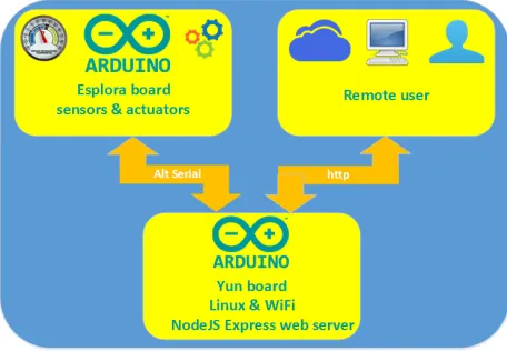
Fig. 3. Configuration of Esplora remote experiment
Microcontroller on Yun1 board is the same as on Esplora, the ATM32u4, while the second processor supporting the Linux platform and WiFi is Atheros AR9331. As the internal communication between Yun processors is based on serial communication, it was not possible to use serial communication with Esplora board, as it did not work. The other protocol, TWI worked well on Yun simultaneously with serial, but Esplora
does not support TWI. At first, the non-optimal solution was implemented, with 3rd
board, the Arduino UNO as a connector between Yun and Esplora. Both serial and TWI worked well on UNO, so UNO was connected with Yun using TWI and with Esplora using serial thus enabling desired connection between Yun and Esplora in both directions.
Later, the AltSoftSerial library [25] was used, which allowed direct serial communi-cation between Yun and Esplora boards, so UNO was not necessary anymore. The AltSoftSerial library is an example of the great community support for Arduino and other SBC devices. Configuration of remote web experiment with Esplora board is presented in Fig. 3. Arduino Yun board acts as a mediator between remote web user and Esplora board. It provides Express [26] web server on NodeJS [27] which accepts user requests and transfers user requests over serial Rx/Tx lines to Esplora board. Yun also accepts responds from Esplora with sensor values and returns it to remote user as updated sensor values in the experiment web page.
Configuration of two processor system on Yun board is presented in Fig. 4. On the left is microcontroller ATmega 32u4 system connected to USB port which is used for upload of program for microcontroller from Arduino development environment.
crocontroller communicates with AR 9331 processor over serial Rx/Tx lines. Processor controls both LAN interfaces, Ethernet and Wifi, SD card adapter and USB host mean-ing that it can control other USB devices. Microcontroller and processor are programed independently. Processor can be accessed through LAN interfaces. Linux configuration takes some time, as it is advised to install latest Linux update on SD card which acts like hard disk for PC platforms. Linux system can be accessed with telnet / SSH and SCP (SeCure coPy) [28].
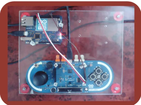
Implementation of sensors & actuators experiment: On Fig. 5 is a photo of two board system, mounted on transparent plastic board for mechanical stability, connected with 3 wires, Rx, Tx and common ground. Besides boards, power supply is required and proximity of WiFi access point. As the Yun board is a server which is in the local network (192.168.x.x) behind single public IP address, it is necessary to create NAT (Network Address Translation) access to static IP address of the YUN board.
Fig. 4. Arduino Yun two processor system
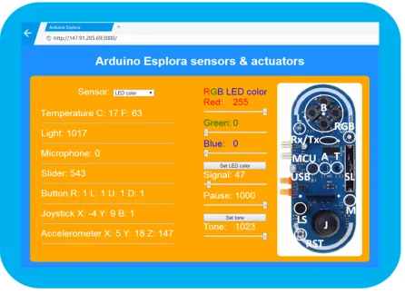
Fig. 6 presents the web page which serves as user interface for Esplora board. On the left are 7 sensors, while on the right are controls for setting the actuators. Only one current sensor or actuator can be selected at a time from drop down list named “Sen-sor”. Name of currently selected element blinks on web page. If a sensor is selected, its value is read every 300 mS. Requests and transferred data are only a few bytes long which does not significantly load the network, and quick responses are expected. Up-dated display of repeated sensor readings creates live impression, as readings of sen-sors for temperature, light, microphone and accelerometer fluctuate naturally. Other sensors react on button press and movement of the joystick and variable resistance slider. Sensor readings are proportional to analog values in binary ranges of 0 – 1023 for light, microphone and slider, 0 +/- 511 for joystick X and Y values, 0 – 255 for accelerometer X, Y, Z axes, and 0 – 1 for buttons.
Fig. 6. Web page with Esplora sensors and actuators
Actuators, the RGB LED diode and small buzzer loudspeaker have sliding controls on the right of web page in Fig. 6. RGB diode can be set to display red, green and blue color in any combination. Color intensities are selected with horizontal slide controls for each color as can be seen in Fig. 6. For buzzer, the tone frequency can be set from 0 to max value with horizontal slider. For both actuators, blinking time intervals for signal and pause can be set in mS, also with appropriate horizontal sliders, simulating audio visual indicators or alarms of some event.
This experiment servers as an example of connecting two Arduino boards for com-bining required complementary functionalities of each board, and an example of using various common sensors and actuators with web user interface.
correspond to a system of the desired order. For such circuits to be of practical use it is important to enable adequate viewing of the phenomena, and to demonstrate all work-ing regimes, the aperiodic, damped oscillations and continuous oscillations by chang-ing of circuit parameters. This is where computers can provide a solution, and wide availability with remote web access.
Not all working regimes are possible in circuits - systems of any order.
• The first order circuit - system can give only aperiodic output with step function on input
• Second order system can output damped oscillations besides aperiodic output, but cannot oscillate continuously
• Third and higher order systems can produce all mentioned regimes, the aperiodic, damped oscillations and continuous oscillations
Using the implementation of remote web experiment for linear analog systems, re-mote users can select system order and damping from the web page, and test behavior of real linear systems with selected order and damping.
Experiment setup & configuration: Setup of experiment with linear systems con-sists of electrical RC circuit with schematic in Fig. 7. There are 5 RC segments serially connected, with output of one RC segment connected to input of the next. Input of the first RC segment is circuit input I, while the output of the last is circuit output O. RC segments are connected by operational amplifiers with voltage amplification of 1, used for decoupling of RC circuits. Output O1 corresponds to system of order 1, while O5 to 5th order system. Outputs O1 – O5 are connected to analog inputs A1 – A5 of Arduino board, with I connected to Arduino PWM analog output. Selection of the system order is accomplished with selection of an appropriate analog input connected to desired output which can be done in software. Changing of the operation regime is performed by changing of the negative feedback which is software implemented, as can be seen in lower part of Fig. 7. G(s) is transfer function of the RC circuit, while the !(s) is transfer function of software implemented feedback. Introduced feedback, which can also be turned off, changes time constant of the RC circuit and damping / quality factor, which changes regime of operation: aperiodic, damped oscillation and sustained oscillation. Intensity of introduced negative feedback is controlled by user from the web page. Fig. 8 presents hardware setup for RC circuit. Power supply provides symmetric +/- voltag-es for operational amplifiers, while the Ethernet Arduino is powered from other 5V power supply. RC circuit is on the white breadboard, while the other smaller white object is temperature & humidity sensor which can be independently accessed remote-ly.
RC experiment configuration in Fig. 9 illustrates distributed configuration. Only two yellow boxes on the left are presented in Fig. 8, while the lower yellow box on the right in Fig. 9 with Intel Galileo board is physically located somewhere else, as it is connected to network. Intel Galileo is also a small SBC which is Arduino compatible and certified [29] providing Express NodeJS web server with web sockets and software client for sending requests to Arduino Ethernet’s tiny web server which just returns requested experimental data in simple JSON form. Example of the returned data in JSON form, from temperature & humidity sensor:
{"LabTemp":24.10,"LabHum":43.70}
Fig. 7. Scheme of experiment with linear systems
Fig. 8. Hardware setup for RC experiment
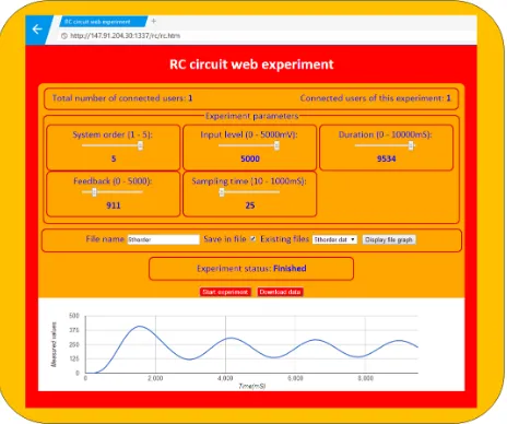
Web page for RC circuit experiment: Remote user directly accesses the web page in Fig. 10 for RC experiment. Horizontal slider controls are for user selection of the system order, level of input step function, exp. duration, feedback intensity and sam-pling time. Slider controls were used instead of free user input, like text input boxes, to prevent users from illegal input, and to avoid user input analysis, with all slider posi-tions and combinaposi-tions being legal. Result of experiment is time dependent output signal from the RC circuit of selected order, and with other user adjustable parameters.
Fig. 10. Web page for RC experiment
Obtained output signal is graphically presented as chart below. It can be seen from Figs. 10 and 11 that the charts of the output signals are completely different for differ-ent values of experimdiffer-ental parameters that define differdiffer-ent experimdiffer-ental conditions. In Fig. 10 system order is 1, feedback is 0, experiment duration is 1S (1000mS) which effectively describes capacitor charging to a voltage given by step input level. In Fig. 11, the system order is 5, feedback is non-zero, and time duration is between 9 and 10 seconds, as the process lasts longer for the system of the higher order. Input level and sampling time are the same for both experiments. Under such conditions, chart in Fig. 11 presents almost sustained oscillation. The higher the order of the system, the easier for the system to oscillate, which can be easily demonstrated with this remote experi-mental setup. Each obtained result is saved in file on server with given file name, or with default file name (which is overwritten for next experiment) if not specified.
Saved files on server with experimental data are listed in drop down list “Existing files” and can be retrieved for displaying of chart on experiment web page, and down-load of measured data in file to user computer.
User administration: Currently, there is no classical user administration for this experiment, as it lasts max 10 seconds. Instead, a simple logic was used, that during experiment execution it is unavailable for all users, including a user that started it. After the experiment is over, it is available for the user that first starts the experiment again. Web page displays the number of users that are connected to server, and number of users connected to selected experiment. Web server on Intel Galileo can be used for more than one remote web experiment. In Fig. 10 there are 3 users, while in Fig. 11 it is 1 user. Web sockets are used for implementation of this simple logic. Web sockets technology enables web server to initiate communication to connected web clients. After the experiment is over, the result data and updated list of experimental files are sent to all connected users. Chart with latest experimental result automatically appears in browsers of connected users, and drop down list with experimental file names is automatically updated with name of the file containing data from latest experiment.
3.2 Solar panel experiment
Solar panel is energy converter that converts energy of light to electrical energy. Light means visible electromagnetic (EM) radiation, while radiation outside visible spectrum can produce the effect as well. Solar panel consists of solar cells which are also called photo voltaic (PV) devices. Light or EM radiation source can be any with sufficient power for measurable effect in experiment. Besides phenomenon demonstra-tion and measurements, the experiment also provides important wider educademonstra-tional content and implicitly points to conclusion that almost all known kinds of energy on Earth, like wind, thunder lightning, fossil fuels, energy of river water are just examples of transformed energy of the Sun radiation to mentioned forms of energy. For that reason, studying of light to electricity converters is important for improvement of pho-to voltaic cells as a significant, clean, practical, renewable and cheap alternative energy sources.
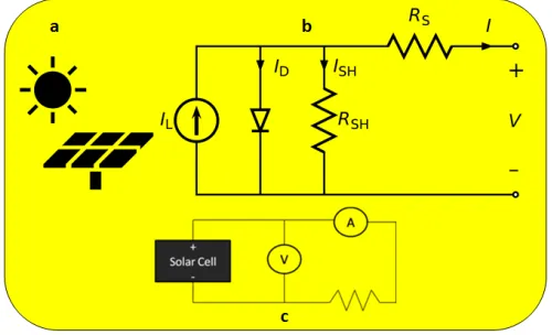
Solar panel experiment setup: Basic setup for solar panel experiment consists of some standard solar panel, light source, variable electric resistance as a load for the solar panel and measurement instruments for voltage and current. Fig. 12 presents the experimental setup.
which defines the output voltage, ISH is current through equivalent parallel internal resistance RSH (shunt), RS is equivalent internal serial resistance, I is output current and V is output voltage measured at solar cell connecting points. In Fig. 12 c is a simple solar cell test circuit for measurement of solar cell output voltage and current for a given value of external resistor. Solar panel consists of solar cells connected in series for obtaining required output voltage higher than single cell voltage, and parallel for obtaining required max output current.
Instead of a single solar cell in Fig. 12 c, a solar panel is used. Connected resistor determines the output current of solar panel for given lighting conditions. Lighting conditions can vary for different light sources and position of the light source. Im-portant feature of solar panel that defines its usability for power supply is voltage / current (UI) characteristic. UI characteristic of solar panel, or a single solar cell in special case, is obtained by measurement of voltage and current with constant lighting conditions and changing external resistor from some large resistance value with max. voltage and min. current, to near zero resistance value with max. current and min. voltage. When the experiment is performed in the lab, resistance is changed manually by a human operator. For the remote access of experiment with solar panel, external resistance value should change automatically. Automated resistance change can be implemented in various ways, using some electromechanical solution involving me-chanical movement which is complicated and expensive, with switching of several fixed resistance values which is better solution, or purely electronic solution using transistor element as a variable resistance which is simple and cheap solution, and which was therefore adopted for this experiment.
Fig. 12. a Solar panel icon; b Solar cell equivalent circuit; c Solar cell test circuit
cheap replacement for true DC DAC, but in the case of driving transistor with high amplification, the PWM produces noise which requires filter circuits for noise suppres-sion. Noise filtering makes the experimental setup unnecessarily more complex, which is why the DUE board was used. Another important advantage of DUE board is a 12-bit resolution both on analog input and output comparing with usual 10 12-bits analog resolution found on other boards.
In order to provide web access and communication between DUE and main web server on Intel Galileo board, Arduino Ethernet shield was mounted on DUE.
Solar panel experiment web page: Web page for solar panel experiment was de-signed in a similar way as for RC circuit experiment. Fig. 14 presents a web page for solar panel experiment. As it is on the same NodeJS Express web server on Intel Gali-leo board, as the RC circuit experiment, the same template for allowing user access to experiment was used.
Fig. 13. Configuration of Solar panel remote experiment
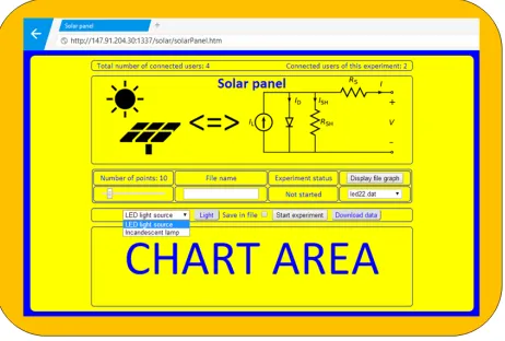
The label “Total number of connected users: 4” means that there are 4 connected us-ers at the moment on server for all experiments, (two experiments at that moment) and label “Connected users of this experiment: 2” means there are two users connected to Solar panel experiment. Web sockets were used for automatic evidence of users. Users are connected clients, which can be 4 different users, but also one user with 4 opened pages in the same or different browsers. The same is for number of users of selected experiment. Presenting number of users on the page with experiment is informative, whether there are other users that might start the experiment as well.
Below the labels is solar panel icon and the equivalent electrical scheme discussed for Fig. 12.
Fig. 14 presents the experiment web page immediately after the page was opened and before the first experiment was started. Label “Chart area” marks place for the chart with solar panel UI characteristic obtained from measurement data. Two light sources can be chosen, the LED light source and classic incandescent lamp. Two solar panels are used, one for each light source, as each light source is positioned closely to corresponding solar panel and centered above the panel for maximum effect. Although some other light sources could be used, two light sources with corresponding panels are due to two channel DAC on DUE. Each DAC drives one transistor as variable load for corresponding solar panel. Some switching would be possible for using of one channel DAC for two or more panels, but that would introduce some extra complexity and also some extra switching, which is the reason for using one DUE board for two light sources. If more light sources should be included in experiment, the elegant solu-tion would be to include addisolu-tional DUE card for control of addisolu-tional two solar panels with corresponding light sources. Such a scenario would be the example of modular expansion of experimental resources with no principal limitations.
Besides light sources, some other experiment parameters can be controlled from web page. Number of points is number of measured UI pairs during one experiment run. Each measured pair of UI values corresponds to one value of variable transistor re-sistance load of solar panel. Number of points is equal to number of rere-sistance values from max to min and can be software adjusted by slider on web page. Measured values during each experiment run are saved in file on server with a given name. If the file name is not specified, or the “Save in file” is not checked, values are saved in file with default file name which is overwritten on the next run. All saved files are listed in drop down list, and can be displayed by selecting from list and pressing “Display file graph” button. For graphically displayed results data from file can be downloaded to user’s computer with “Download data” button.
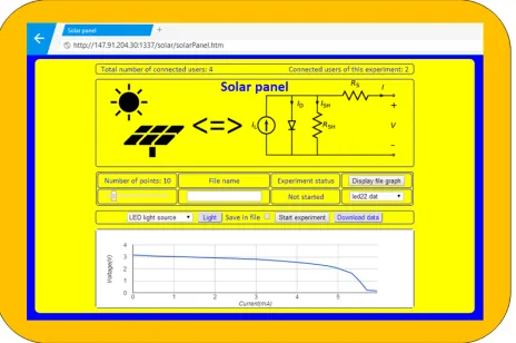
Fig. 15 presents web page with displayed chart from data in selected file. “Light” button is for quick test of selected light source. Each click turns on or off the selected light source. LED light source is low voltage and can be directly controlled from digi-tal output. Incandescent lamp is for 220V and is controlled with electric relay element which is driven from digital output. When the experiment is started, light is automati-cally turned on before measurements, and turned off after measurements.
current measurement. Current measurement error due to transistor base current from DUE analog output is negligible for small values of measured current, less than 1% as the used transistor current gain is of the order of 900. But as the base current grows to drive transistor resistance to small values, it finally visibly adds to measured value of current. Therefore, the final part of the chart with horizontal line and corresponding data should be excluded. Measurement error due to additional base current can be substantially reduced by using FET (Field Effect Transistor) transistor which is voltage controlled instead of current.
4
Conclusion
Arduino family of boards can be quite successfully used for implementation of vari-ous tasks for remote control and measurement which do not require performances exceeding Arduino boards capacities. Various Arduino boards and shields can be used in various combinations from single board to connected boards with shields for added functionalities. Low price, reliability, low consumption, small dimensions, with all required functionalities make Arduino and brands of similar boards ideal candidates for implementation of tasks requiring interaction with environment and continuous opera-tion. For educational purposes, remote experiments with web access require reliable devoted devices and equipment for continuous operation with affordable prices for sustainable projects. Arduino boards featuring such characteristics are discussed from various aspects including basic types of boards, typical design configurations with general design template, various board interconnections and remote access. According to discussed general configuration template three remote experiments with web access were implemented exclusively with Arduino boards. Each experiment was discussed from the aspects of general description, educational aim and requirements, specific experimental setup, configuration with Arduino boards, and user web interface. User administration was not implemented, only the basic competitive access to experiments. Although the user administration is important, and can be implemented on Arduino platform, it was not the focus of this paper. Possible improvements of presented exper-iments are mainly matter of experimental setup, while configuration can be easily ex-tended with additional boards.
5
References
1. “Arduino” [On line] Available: http://arduino.cc
2. “Arduino” [On line] Available: http://arduino.org
3. M. "valjek, Arduino Succinctly, Syncfusion Inc., 2501 Aerial Center Parkway Suite 200 Morrisville, NC 27560 USA, 2015, http://www.syncfusion.com/
4. A. D’Ausilio, Arduino: A low-cost multipurpose lab equipment, Behavior Research Meth-ods, vol. 44, 2, pp 305-313, 2012, http://dx.doi.org/10.3758/s13428-011-0163-z
5. “BeagleBone Black” [On line] Available: http://beagleboard.org/BLACK 6. “Raspberry Pi” [On line] Available: https://www.raspberrypi.org/
7. I. Jacobson, G. Booch and J. Rumbaugh, The Unified Software Development Process, Ad-dison-Wesley Longman Publishing Co., Inc., Boston, MA, USA, 1999
8. T. Kozik and M. "imon, Preparing and managing the remote experiment in education, 15th International Conference on Interactive Collaborative Learning (ICL), 26 - 28 September 2012, Villach, Austria https://doi.org/10.1109/ICL.2012.6402077
9. “Arduino Forum” [On line] Available: https://forum.arduino.cc/ 10. “Arduino Forum” [On line] Available: http://www.arduino.org/forums 11. “Arduino GitHub” [On line] Available: https://github.com/arduino 12. “Adafruit GitHub” [On line] Available: https://github.com/adafruit
13. “Arduino Sparkfun GitHub” [On line] Available: https://github.com/spark fun/Arduino_Boards
14. “Arduino Ethernet” [On line] Available: http://www.arduino.org/products/boards/arduino-ethernet
15. “Arduino UNO” [On line] Available: http://www.arduino.org/products/boards/arduino-uno 16. “Ethernet shield” [On line] Available:
http://www.arduino.org/products/shields/arduino-ethernet-shield-2
17. V.M. Cvjetkovi#, M.Matijevi#, Overview of architectures with Arduino boards as building blocks for data acquisition and control systems, 13th International Conference on Remote Engineering and Virtual Instrumentation (REV), 24-26 February 2016, UNED, Madrid, Spain https://doi.org/10.3991/ijoe.v12i07.5818
18. “Arduino Esplora” [On line] Available: http://www.arduino.org/products/boards/arduino-esplora
19. V. Cvjetkovic, On Line Experiments with linear analog systems from the first to nth order, REV 2006 (Remote Engineering and Virtual instruments), 29 - 30 June 2006, Maribor, Slovenia
20. “Photo voltaic devices technical note” [On line] Available: http://www.bentham.co.uk/ pdf/PV_Technical_Note.pdf
21. “Arduino IDE” [On line] Available: https://www.arduino.cc/en/Main/Software 22. “Arduino IDE” [On line] Available: http://www.arduino.org/downloads
23. “Esplora pinouts” [On line] Available: http://21stdigitalhome.blogspot.rs/2012/12/esplora-expansion-header-pinouts.html
24. “Arduino Yun” [On line] Available: http://www.arduino.org/products/boards/arduino-yun 25. “Alt Soft Serial” [On line] Available: http://www.pjrc.com/teensy/td_libs
_AltSoftSerial.html
26. “Express” [On line] Available: http://expressjs.com/ 27. “NodeJS” [On line] Available: https://nodejs.org/en/
28. “WinSCP” [On line] Available: https://winscp.net/eng/index.php
29. “Intel Galileo” [On line] Available: https://www.arduino.cc/en/ArduinoCertified/ IntelGalileo
6
Authors
V. M. Cvjetkovic is with the University of Kragujevac, Faculty of Science, Kragu-jevac, Serbia (e-mail: [email protected])
U. Stankovic is with the University of Kragujevac, Faculty of Science, Kragujevac, Serbia (e-mail: [email protected])