Techniques for Dynamic Damping Control in Above
Knee Prosthesis
Hemant Kr. Anand, Rachit Rastogi, Prof. G. C. Nandi
Indian Institute of Information Technology, Allahabad
Deoghat, Jhalawa, Allahabad, INDIA - 211012
Abstract
The paper presents a new technique for dynamic damping control based on natural humanoid walk for above knee prosthesis. It has been observed that natural humanoid walking is not solely relied on sensory feed back but also on Central Pattern Generators (CPG) and this CPG pro-duces variation in joint trajectories based on task. Devel-oping task oriented active prosthesis exploiting biologi-cally inspired CPG patterns are of main focus of the paper. Task oriented stable gaits were synthesized using ZMP (Zero Moment Point) approach and the results were com-pared to kinematics of subjects captured by video stream-ing. Initial results suggest a feasible solution to gait pattern generation and adjustment of damping profile of prosthetic knee joints to achieve normal humanoid walking.
Key words— Active Prosthetic knee, Biped locomotion, Central Pattern Generator (CPG), Zero Moment Point (ZMP).1. Introduction
1. Inrtoduction
HUMANOID robot research and development of active prosthetic knee joints has made remarkable progress in the two decades.
Commercial availability of humanoid robots such as Asimo(Honda)[1], QRIO (Sony Dream Robot)[2] and HRP -2 (AIST) strengthens the above fact, but still achiev-ing humanoid walkachiev-ing control remains a challenge. The need of a strong support for body weight on stance leg, shock absorption at heel strike and flawless stair climbing pose a lot of problems. Extending humanoid robotic re-search towards lower limb prosthesis in humans has also taken big leaps with the existence of semi active prosthetic limbs. C-Leg (Ottobock)[3] is an example of such a mi-croprocessor controlled knee joint. Biped locomotion strategies can be used to develop humanoid walking in robots and also in prosthetic limbs. Modern knees are be-ing developed usbe-ing highly adaptive, electronically con-trolled hydraulic actuators. These intelligent knees use computational intelligence, and with sensory information adjust damping during the swing and stance phase at dif-ferent walking speeds [11]. To develop this computational intelligence and obtaining accurate damping parameters is
the primary aim of this paper.
Various approaches have been followed in studies around the world for humanoid walking control like passive dy-namic walking system (PDW) [4], Central Pattern Genera-tor (CPG)[6][7][8], Zero Moment Point (ZMP) tracking [1][16], learning and divide-and-conquer [10]. Other re-searchers applied various soft computing techniques to tackle the humanoid walking problem. Such a work is done by C. Paul [5] using Artificial Neural Networks (ANN). Biological similarity and stability of Neural Oscil-lators for producing sustained oscillations has made oscil-lator based CPG design a focal point of various humanoid walking studies. A neural system model for 3D adaptive quadruped walking is shown by Kimura et. Al [6] , while a biped walking control has been solved by G. Taga.[7] us-ing oscillator based CPG. A rhythmic arm control usus-ing oscillators has been designed by Williamson [8]. Extend-ing these works a design scheme for CPG and its applica-tion to active prosthetic knees has been proposed.
Along with walking human beings perform vari-ous non conventional gait patterns. We frequently carry backpacks, suitcase, buckets, trays etc. while walking. Stable walking has been realized by various researchers using zero moment point approach [16] but little analysis has been done on weight based gait pattern generation. Miomir Vukobra tovi´c had proposed methods of walking pattern synthesis based on zero moment point (ZMP) [16]. Biped robot stability with the ZMP tracking was also dy-namically analyzed by Hirai in ASIMO [1].
This paper attempts to generate the stable gait for hu-manoid walking with weight using a simplified biped model based on ZMP.
2.CPG based locomotion
2.1. Physical biped model
A 5-link biped robot has been modeled for simulation study of walking robots. Key parameters of the biped are given in table 1.
Single DOF(pitch) is incorporated at hip and knee joints. Such a simulation will help in analysis of human gait as demonstrated later with IGRIP human model simu-lations.
2.2. Central Pattern Generator
2.2.1 Oscillator mechanism
. For design of CPG the Neural oscillators developed by
Matsuoka [9] have been used which solve the nonlinear dynamics using first order differential equations given below. The stability and entrainment characteristics of the oscillators have been extensively studied and applied in biped and quadruped locomotion [6][7]. The characteristic equations of the mutually inhibiting neurons in a neural oscillator are as follows
Tr*∆Xi/∆t = -Xi – b*Yi + c – w*max(0,Xj)
+ ∑a(i,k)* max(0,X(k))+h*Feed(i) (1)
Ta ∆Yi/∆t = -Yi + max(0,Xi) (2)
Tr*∆Xj/∆t = -Xj – b*Yj + c – w*max(0,Xi) +
∑a(i,k)*max(0,X(k))+h*Feed(j) (3)
Ta ∆Yj/∆t = -Yj + max(0,Xj) (4)
Where Tr and Ta represent the rise time and adaptation time for neurons and are responsible for frequency and shape of output of oscillators along with inter oscillator
connection weights. X is a variable that represents the de-gree of fatigue or adaptation in the neuron and b is the parameter that determines the steady-state firing rate for a constant input. The weights(w) of connection between oscillators have been kept constant throughout the simula-tion. Input c is used to vary amplitude of joint angles.
Oscillatory sensory feedback Feed(i) and Feed(j) pro-vides necessary entrainment with feedback gain h, hence accounting for environment change, which has been shown in Fig 2.
Output of the mutually inhibiting neurons in an oscilla-tor provides the angular change in opposite directions for symmetrical out of phase oscillations.
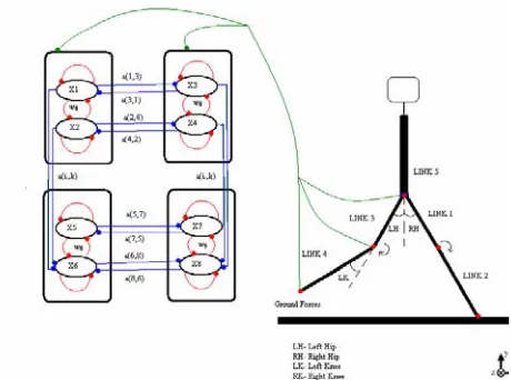
2.2.2 Oscillator coupling for locomotion
Earlier designs suggesting the existence of two mutually inhibitive neurons for each joint has been followed to gen-erate rhythmic patterns of gait. The oscillator outputs have been used for computing joint angles which correspond to extensor and flexor angles of antagonistic muscles for each joint.
This interconnection of oscillators provides inverse phase relationships between contra lateral and ipsilateral sides for symmetrical motion. Optimal values of weights have been carefully chosen through hand tuning to give acceptable response over a wide range of frequencies and patterns generated for gait.
2.2.3 Sensory Feedback
The importance of feedback is well understood in closed loop systems with feedback providing the interface with the environment for improved control and achieving steady state of the system. Our model also follows the feedback signals for locking of oscillator frequency with the oscillatory input signals from hip angle, knee angle and ground forces as shown in Fig 2.
[image:2.612.70.298.93.416.2]In human walking visual inputs play an important role in dynamic obstacle avoidance, but small changes in slope and unevenness of terrain can be handled with sensory input from foot only. Paramters used in CPG design using
Fig. 2. Interconnections of oscillators and feedback connec-tions.
TABLE 1 KEY PARAMETERS OF BIPED
Link
1 Link 2 Link 3 Link 4 Link 5 Length
[meters]
0.5 0.6 0.5 0.6 0.5 Mass
[Kg] 7.5 5 7.5 5 30
(a)
(b)
Fig. 1. Bipedal walking models (a) 5-link biped (sagittal view) (b) IGRIP humanoid (frontal view)
TABLE 2 KEY PARAMTERS OF CPG
Ta Tr b w h
Hip 0.05 0.6 2.69 2.0 0.05
[image:2.612.332.562.389.560.2]oscillators are given in table 2.
Next section explains ZMP based locomotion and algorithm based decision of most stable trajectory.
3. ZMP based locomotion
3.1. Bipedal Model
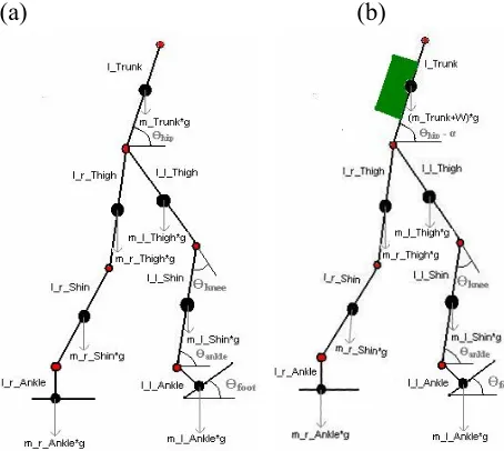
The biped planar model used here for analysis was a 7 Link model with 6 Degrees of Freedom given in fig 3(a); model carrying weight is shown in 3(b). The key specifica-tions of bipedal model are given in Table 3. In case of normal walking subject puts the body in Single & Double support Phase [16] alternatively and by applying the for-ward force during stance it accelerates forfor-ward. The time for Single Support Phase is very less (as compare to the Double Support Phase). Also, the Single Support phase is inherently unstable hence a small interval of 0.01 Second is chosen during the Walking Cycle.
3.2. Mathematical Model for Trajectory
gen-eration
A model based approach was used for deciding the
trajectories of different joints. The foot and hip
trajectory were calculated mathematically and optimized using algorithmic approach given in section 3.3. Finally knee trajectory was interpreted from hip and ankle joint positions.
Parameters given in Table 4 were used for caluculation of foot trajectory through 3rd order Spline Interpolation.
Hip trajectory plays an important role in designing the bipedal walking system and also providing stability to the amputee wearing an artificial limb. Hence an algorithmic
approach was devised to obtain optimized walking with varying load on the back of the subject. Hip oscillates from minimum to maximum height in one step of gait cycle. Velocity and acceleration at start and end of each step are assumed to be zero. Several Hip trajectories were generated in a particular posture by varying hip to ankle distances. With the help of ZMP control algorithm we select the trajectory which produces ZMP that covers the largest stability margin.
Smooth and reliable knee trajectory for BKA (Below Knee Amputations) was achieved with the help of the algorithmic technique given in the next section.
3.3 ZMP control algorithm
Algorithm sequence is as follows:I: Set the biped parameter (e.g. walking speed, obstacle height, step length etc.).
II: Generate the foot trajectory using 3rd order spline. III:Set the parameters (Hip_Ankle_Forward_Distance (HAFD) & Hip_Ankle_Backward_Distance (HABD)).
IV: If (HAFD > (Step_length)/2 and HABD > (Step_length)/2 ) goto step V
a: Generate hip trajectory using 3rd order spline. b: Compute weight based ZMP & Stability Margin. c: Increase HAFD & HABD.
d: Choose hip trajectory with largest stability margin. e: exit
V: Exit
ZMP trajectory produced by the algorithm is unique and gives the biped system almost similar movement as subject is having while carrying the weight.
ZMP can be calculated with the help of following for-mula:
TABLE 4
PARAMETERS FOR WALKING CYCLE
Parameters Length of Step
Period of Step
Height of Step
Foot Angle (Start)
Foot Angle (End) Value 0.5
meter 0.9 Sec 0.16 meter 0.2 radians 0.2 radians
(a)
(b)
[image:3.612.80.307.363.566.2]Fig. 3. Sagittal view of Bipedal Model (a) Without Load (b) With Load
TABLE 3 BIPED MODEL PARAMETERS
Link
Pa-rameters Trunk Thigh Shin Ankle Foot Mass
(In Kg)
43 10 5.7 - 3.3 Length
[image:3.612.87.307.620.693.2](5) where,
(Xzmp,Yzmp) are the co-ordinates of ZMP position, Linera & Angular Acceleration in Z and X are measured as a parameter in ZMP.
Oscillator based CPG provides the angular patterns in gait cycle and ZMP based synthesis gives a stable trajec-tory for locomotion. The two approaches are then inte-grated in the design schema given in next section for damping adjustments in active prosthetic knee.
4. Active Prosthetic Knee control
Knee damping adjustment in semi active prosthetic knee joints is done by trained prosthetists based on the feedback from the amputee. This process is used in C-Leg shown in Fig 4 (b). The damping factors once adjusted remain con-stant without any consideration of walking speed, weight and gait patterns of a person. Manual interference required to adjust knee resistance is error prone and inaccurate. Hence a dynamic controller is proposed here.
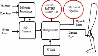
Prosthetic knee control requires efficient sensing (from the view point of effective ness and accuracy) from both global and local sensors which in our design includes knee angle, hip angle and ground reaction forces. These sensed signals are then preprocessed to obtain velocities and ac-celerations of the knee and hip.
The ground forces are captured using strain gage sen-sors, although as a simplification of foot model we are using point contact with the ground. The damping given to the knee varies in each phase of the gait cycle depending upon the sensor information. Our CPG model computes the expected angles and velocities depending upon the sensory feedback. Stance phase damping is varied in-versely depending upon the position of hip joint with re-spect to the knee joint. In turn, the swing phase damping is inversely proportional to the difference between maxi-mum flexion angle obtained through CPG and biologically limiting flexion (taken as 70 deg). These computed values are then used to adjust the resistance offered by prosthetic knee joint to achieve biologically realistic gait. The basic design flow of damper controller is given in fig 4. (a).
Biped model was used to give the inputs in the form of
joint angles and ground forces. The term which primarily affects the gait is the variable weight the subject is carry-ing values were passed to the ADC module which will serve as an entry gate for the Digital System. ADC outputs the bit stream which was given as an input to microproces-sor. The ZMP control algorithm mentioned earlier gives the optimized and stabilized trajectory.
5. Results and discussion
5.1 CPG results
Implementation of CPG and Stick diagram simulations of humanoid biped walking has been done using MAT-LAB 6.5. The weights of connections between oscillators were decided using hand tuning and remain constant throughout the simulation. Input to oscillators is used to observe the variations in the step length, stride length of biped gait pattern. Time constants have been chosen to receive optimal results close to human like gait and also to vary the frequency of walking.
Joint angles and velocities have also been obtained us-ing human model in IGRIP software.
Leg joint angles vary between the ranges given in table
5. (Measured as in fig. 2)
The similarity between the oscillator signals and IGRIP simulated gait patterns confirm the correctness of results. Although slight variations from real human gait patterns is seen because of incomplete modeling of foot. First 2-3 steps showed unstable joint patterns which gradually turned into stable gait pattern as desired as evident from the angular plots in fig 5. An increase in frequency of os-cillation was seen by giving sensory information to oscilla-tors.
Fig 4.a Active damping control
[image:4.612.362.546.84.256.2]Fig. 4 (b) C-leg Heel Strike displayed
TABLE 5
ANGLE MINIMUM AND MAXIMUM (IN DEGREES)
Joint Min Max
Hip -30 30 deg
[image:4.612.347.539.562.609.2] [image:4.612.80.244.604.698.2]The speed of walking is controlled using step length or varying the frequency of oscillator outputs.
A stable phase response for knee angles were obtained using simulations as shown in fig 7. Although slight
varia-tions from real walking was seen with the drop of knee angle below 0 degrees.
5.2. ZMP Control
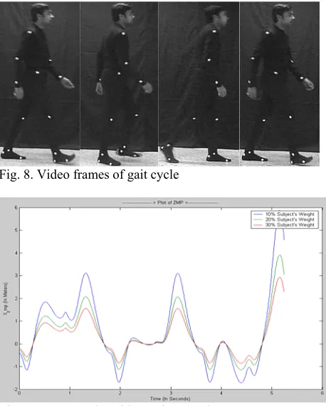
All Simulations were made using MATLAB 6.5. The results were compared to the kinematics of subjects in spe-cific situations. To generate the trajectory from subject’s body, the video was captured in sagittal plain and joint markers shown in fig 8 were segmented out through inter-polation. For video streaming analysis and segmentation of frames VirtualDubMod was used and ANOVA [18] was used for statistical analysis of variance in Video Data.
It was observed that while loading the weight on the back of subject the trajectory of ZMP is shifted down and the step length becomes small as indicated by the plots in fig 9. In critical conditions it has been observed that in-creasing the weights beyond certain level does not cause much change in trunk bending.
Stick diagram for the Bipedal Model drawn at an inter-val of 0.1 second is given in fig 10.
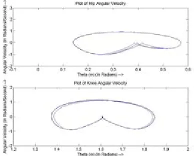
Phase plots for hip and knee joint angles is given in Fig.11 above; which demonstrate the stability of angular plots obtained from ZMP approach.
[image:5.612.80.309.122.294.2]Fig. 12 shows the damping force (which has been de-fined to be the variable force experienced by both the legs during the different phases of walking. It is measured in Newton) plotted for right and left knee based on control strategy mentioned in section 4. It shows a spike in the middle of stance phase which indicates high damping to resists stance knee bending due to body weight.
[image:5.612.329.558.184.469.2]Fig. 5. Angle plot for CPG and IGRIP simulations (Right knee above and Left knee below)
[image:5.612.78.310.237.675.2]Fig. 6. Stick Picture for Bipedal walking simulations (every 0.4s interval) at c=4
Fig. 7 .Phase plot for Right knee
Fig. 8. Video frames of gait cycle
[image:5.612.78.311.333.482.2] [image:5.612.78.310.482.653.2]6. Conclusions
In this work we verify the results of a rhythm generator based on Matsuoka oscillators to obtain a stable symmetri-cal pattern of movement between leg joints, and compare it with the patterns obtained by humanoid walking produced
using IGRIP. Architecture for evaluation of stance and swing phase damping for active prosthetic knee based on the joint patterns obtained using our simulations has been presented. Unique and stable trajectory was obtained using ZMP for the biped model carrying weight. The trajectory was verified with subject motion through video streaming. It has been seen from simulations that the gait pattern of an individual significantly depends on the task he/she is per-forming or the type of load he/she is carrying. So for de-signing active prosthesis damping cannot be effectively adjusted only based on knee/hip joint trajectories rather the control strategy should include the task based CPG pattern changes to provide maximum comfort to the amputee. It will be an interesting area of research to incorporate this task based CPG in the feedback loop for real time active damping control for a low cost above knee prosthesis.
References
[1] K. Hirai, M. Hirose, Y. Haikawa and T. Takenaka, “The development of Honda Humanoid robot,” in Proc. IEEE Int. Conf. Robotics and Automation, 1998, pp. 1321–1326.
[2] Sony Dream Robot
http://www.sony.net/SonyInfo/QRIO/top_nf.html [3] C-Leg.
http://www.ottobockus.com/products/lower_limb_pro sthetics/knees.asp
[4] T. McGeer: “Passive Dynamic Walking”, Interna-tional Journal of Robotics Research, pp. 62-82 (1990). [5] Chandana Paul, “Bilateral Decoupling in the Neural
Control of Biped Locomotion,” in International Sym-posium on Adaptive Motion of Animals and Ma-chines(2003).
[6] H.Kimura, Y.Fukuoka, K.Konaga, Y.Hada and K.Takase, “Towards 3D Adaptive Dynamic Walking of a Quadruped Robot on Irregular Terrain by Using Neural System Model,” in International Conference on Intelligent Robots and Systems(2001).
[7] Taga, G., Yamaguchi Y. and H. Shimizu, “Self organ-ized control of bipedal locomotion by neural oscilla-tors in unpredictable environment,” in Biological Cy-bernetics(1991).
[8] Williamson, M. M., “Rhythmic Robot Arm Control Using Oscillators,” In Proc. of IEEE/RSJ Int. Conf. on Intelligent Robots and Systems Victoria, pp.77-83, (1998).
[image:6.612.83.304.70.242.2][9] Matsuoka, K. “Mechanisms of frequency and pattern control in neural rhythm generators” in Biological Cybernetics, 56:345-353 (1987).
[image:6.612.98.292.299.455.2]Fig. 10. Stick Diagram for Bipedal Walking (every 0.1s in-terval)
[10] Chee-Meng Chew, Eddie Choong, Aun-Neow Poo, Geok-Soon Hong, “From science fiction to reality – humanoid robots” First Humanoid,
Nanotechnol-ogy, Information TechnolNanotechnol-ogy, Communication and Control Environment and Management (HNICEM) International Conference, March 27-30, 2003, Ma-nila, Philippines.
[11] Herr H, Wilkenfeld A. “User-Adaptive Control of a Magnetorheological Prosthetic Knee.” Industrial, Robot: An International Journal. 2003; 30: 42-55. [12] A. Morecki and K.J. Waldron, editors. “Human and
Machine Locomotion,” chapter Dynamic Models, Control Synthesis and Stability of Biped Robots Gait, pages 153–189.Springer-Verlag, Wien, 1997 [13] Qiang Huang, Kazuhito Yokoi & Shuuji Kajita,
“Planning Walking Patterns for a Biped Robot” IEEE Transactions on Robotics and Automation, Vol. 17, No. 3, June 2001.
[14] C. Chevallereau, A. Formalsky, B. Perrin, “Low Energy cost reference Trajectories for a Biped
Ro-bot”, Proceedings of the 1998 IEEE International Conference on Robotics & Automation May 1998.. [15] Masaki Oshita, Akifumi Makinouchi, “Dynamic
Motion Control for Physically-Based Real time Human Animation”, Computer Graphics Forum, Vol. 20, No. 3, pp. 192-202, September 2001, EU-ROGRAPHICS 2001.
[16] Miomir Vukobratovi´c, Branislav Borovac, “ZERO-MOMENT POINT - Thirty Five Years of It’s Life”, International Journal of Humanoid Robotics, Vol. 1, No. 1 (2004) 157–173.
[17] Jing Xian Li1 and Youlian Hong,2 “Age Difference in Trunk Kinematics during walking with different Backpack weights in 6 to 12 years old chil-dren”.unpublished.