Design and Simulation of 2.4GHz CMOS
Frequency Synthesizer with Programmable
Frequency Divider
A. M. Chauhan V. H. Nayak
Department of Master Engineering in Signal and Communication System Engineering
Department of Master Engineering in Signal and Communication System Engineering Silver Oak College of Engineering and Technology,
Ahmedabad, Gujarat, India
Silver Oak College of Engineering and Technology, Ahmedabad, Gujarat, India
Dr. A. C. Suthar S. D. Shah
L. J. Institute of Engineering and Technology, Ahmedabad, Gujarat, India
L. J. Institute of Engineering and Technology, Ahmedabad, Gujarat, India
Abstract
The frequency synthesizers are an essential part of any modern communication system. The frequency synthesizer is an electronic system for generation of one or more frequencies from one reference frequency sources. The frequency synthesizer is required for carrier generation and found in many modern devices like radio receiver, satellite receiver, wireless network devices, GPS system etc. With the increasing demand for low cost and high performance of wireless transceiver building blocks, the low-power requirement is a great concern for RFIC designers. Concern for frequency synthesiser is low-cost CMOS process in the higher frequency (GHz) range and phase noise. The performance in channel selection of frequency synthesizer and power consumption are limited by the two most important building blocks are the programmable frequency divider and the voltage-controlled oscillator (VCO). The objective of this research work is to design blocks for the frequency synthesizer with low power requirement. 2.4-2.48 GHz band is ISM band, so we can develop system in this band with 5 MHz reference frequency.
Keywords: Frequency synthesizer; CMOS; RFIC; charge pump; programmable frequency divider; lc VCO
_______________________________________________________________________________________________________
I. INTRODUCTION
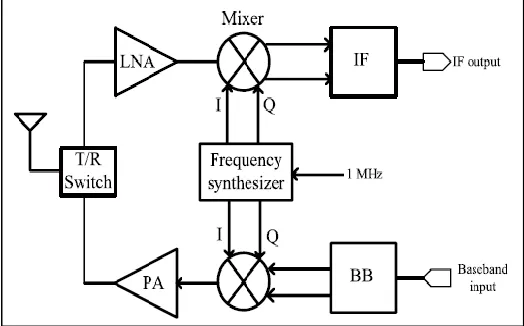
The frequency synthesizer is regarded as one of the most critical modules in modern wireless communications systems. Figure 1 shows the block diagram of a typical modern transceiver. The output signal generated by the frequency synthesizer is normally termed as the local oscillator (LO) signal, at the receiver side the high frequency signal is used to down-convert the incoming signal into a lower frequency IF where it can be processed to extract the information it is carrying. The same LO signal can be used to up-convert the baseband signal to an RF frequency, so that it can be transmitted over the medium.
Fig. 1: The role of frequency synthesizer in a transceiver
II. LITERATURE REVIEW
range.0.18um CMOS technology is used, Power dissipation:18.4mW Phase noise:-114.79dBc/Hz In [2] a new supply regulated LC-VCO that reduces the impact of process variations and temperature on current consumption and phase noise. In reference [3] indirect synthesis uses a PLL Programmable frequency divider in the loop using three or four 4-bit BCD counter stages providing a large number of frequencies from a single reference frequency CMOS 0.18um technology with An integer-N fully programmable divider employs a novel TSPC 47/48 prescaler and 5 bit P and S counters are used. The PLL uses a series quadrature VCO (S-QVCO) to generate quadrature signals Phase noise:-122.4dBc/Hz. Power dissipation: 7.0mW In [7] a switched varactor array based LC-VCO is used, the charge pump current is programmed proportional to division ratio. In reference [3] The programmable loop divider uses the pulse-swallow made up of adivide by N/N+1 prescaler, a fixed divide-by-P program counter and a programmable swallow (S-) Counter ,a single synthesizer with a dual-band VCO used to generate two separate frequency band.. With 0.18um technology, Power dissipation: 22.7mW, Phase noise:-132.6dBc/Hz In [7] with noise filtering technique a hybrid fractional-N frequency synthesizer for wireless application is implemented with TSPC. With 0.18um technology Phase noise:-113.51dBc/Hz. Power dissipation: 20mW
Fig. 2: Block diagram of frequency synthesizer
III. STUDY OF DIFFERENT BLOCKS
Blocks are explained below.
Phase Detector
A PD is a circuit whose average output is proportional to the phase difference between its two input, the relationship betweenand is linear the gain of the PD is KPD expressed in V/rad.
An example of phase detector is the exclusive OR (XOR) gate, the phase difference between the inputs varies, so does the width of the output pulses, So by providing a dc level proportional to phase . The XOR PD produces error pulses on both rising and falling edges.
Tri-State Phase Frequency Detector (PFD)
The DFF and EXOR based PD’s fail to detect the frequency difference and are not suitable for PLL applications where initial VCO oscillation frequencies are far away from reference.
Fig. 3: Phase Detector
Charge Pump and Loop Filter
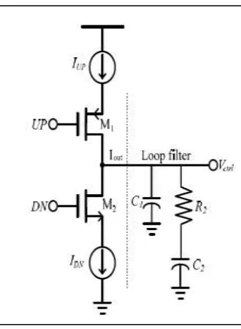
Fig. 4: Charge pump with loop filter
A charge pump generally consists of two current sources that are switched on and off at the proper instance of time[11] A Positive pulses appear at UP while DN stays at 0. Under this condition, M1 is on and M2 is off such that the current IUP charges the loop filter to pull-up the VCO frequency. When positive signal appear at UP while DN stays at 0. Under this condition, M1 is off and M2 is on such that the current IDN discharges the loop filter to pull-down the VCO frequency[12]. During locked condition, both M1 and M2 are on for a short period which is equal to the dead zone pulse width and net current flowing into the loop filter is negligible. Values of C1, C2, R2 can be given as from given equations[12].
C2= Icp*Kvco 2πN(Wn)^2
C1 =C2
16
R2 = 1
2πWz1C2
WhereWc = loop bandwidth Wn = natural frequency = Wc/2 Wz1= zero frequency =Wc/4 N = division ratio
LC Voltage Controlled Oscillator (VCO)
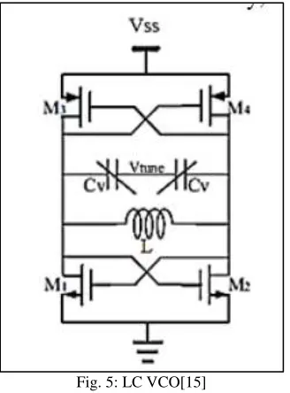
The voltage controlled oscillator (VCO) is an important building block of a synthesizer which generates signals. Both ring oscillators and LC oscillators are used in GHz range applications. But ring oscillators suffer from poor phase noise compared to that of LC oscillators and are less suitable for high-end wireless communication systems. LC oscillators are more attractive due to their better phase noise performance and lower power consumption [12]. Main disadvantage is, they occupy larger area compared to that of ring oscillators. Here MOS varactor is used to tune frequency.
Frequency Dividers
Fig. 5: LC VCO[15]
Digital frequency dividers which divide the input signal by N times are normally termed as modulo-N counters which can be classified as ring or binary counters. Modulus counters need to incorporate programmable logic circuits to provide various division ratios. As it is obvious, we have replaced S counter and P counter with an integrated P&S counter. Output of integrated P&S counter controls Modulus logic bit of prescaler[9]. Here we channel space of 5MHz, the frequency band from 2405MHz to 2480MHz we need a frequency divider from 481 to 496 to cover all 16 available channels. These numbers can be obtained by a divide-by-7/8 dual modulus prescaler (M=7),P = 64 and 33 ≤ S ≤ 48.
Fig. 6: Asynchronous programmable modulo-P counter
Dual Modulus Prescaler
Fig. 7 shows divide-by-7/8 prescaler includes a divide-by-3/4 dual modulus prescaler and a divide-by-2.
Fig. 7: Dual modulus prescaler
Integrated P&S counter
Fig. 8: Integrated P&S counter
For predefined C value (C4C3C2C1C0), prescaler divide input frequency by 8 and for rest of number (64 – C) it divides input frequency by 7. For a cycle we will have:
N = 8*C + 7*(64 –C) = 7*64 + C fvco = fref * N = 5MHz * (448 + C) 2405MHz ≤ fvco ≤ 2480MHz
For 30 ≤ C ≤ 45
IV. SIMULATION RESULT
Simulation results are shown below,
Fig. 9: Vcntr(v) Vs Fout(GHz)
Fig. 11: VCO output for Vcntr=0.23v
V. RESULTS
This research work focuses on the design techniques of PLL based frequency synthesizer low power requirement and performance of designed synthesizer is shown below.
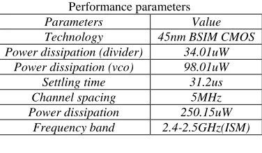
Table – 1 Performance parameters
Parameters Value
Technology 45nm BSIM CMOS
Power dissipation (divider) 34.01uW
Power dissipation (vco) 98.01uW
Settling time 31.2us
Channel spacing 5MHz
Power dissipation 250.15uW
Frequency band 2.4-2.5GHz(ISM)
VI. CONCLUSION
This research work focuses on the designing of frequency synthesizer for 2.4 GHz ISM frequency band with low power requirement and integer N division of frequency, lower phase noise by using proper design of VCO and programmable frequency divider using CMOS 45nm technology results shows with channel spacing of 5 MHz, power dissipation of 250.1uW only and settling time of 31.4us.
REFERENCES
Papers:
[1] Jhin-Fang Huang, Wen-Cheng Lai and Chu-Hao Fu“A 2.4GHz Fractional-N Frequency Synthesizer with Noise Filtering Technique for Wireless Application” 978-1-4799 -4208-4/15 2015 IEEE
[2] Xiaolong Liu, Lei Zhang, Li Zhang, Yan Wang, and Zhiping Yu “A 3.45-4.22 GHz PLL Frequency Synthesizer with Constant Loop Bandwidth for WLAN Applications” 978-1-4799-4132-2/14 2014 IEEE pp. 745-752.
[3] Masoud Moslehi Bajestan, Eugene Foli, Hajir Hedayati, and Kamran Entesari “A 1.6GHz/4.8GHz Dual-Band CMOS Fractional-N Frequency Synthesizer for S-Band Radio Applications” IEEE Radio Frequency Integrated Circuits Symposium 2014 978-1-4799-3864-3/14 pp. 429-435.
[4] Radu Gabriel Bozomitu, Vlad Cehan, Constantin Barabaşa, Neculai Cojan “A VLSI Implementation Of A Frequency Synthesizer Based On A Charge Pump PLL” IEEE 20th International Symposium For Design And Technology In Electronic Packaging (SIITME) 2014 978-1-4799-6962-3/14 pp. 141-145. [5] Sudip Shekhar, Daibashish Gangopadhyay, Eum-Chan Woo, and David J. Allstot “A 2.4-GHz Extended-Range Type-I ΣΔ Fractional-N Synthesizer With
1.8-MHz Loop Bandwidthand−110-dBc/Hz Phase Noise” IEEE Transactions On Circuits And Systems—ii: Express Briefs, Vol. 58, No. 8, August 2011 1549-7747 pp.472-476.
[6] Wen-cheng Lai, Jhin-fang Huang, Jia-lun Yang And Chieh Wen Shih “A Frequency Synthesizer With A Discrete-time Sample-hold-reset Loop Filter Dedicated To Implantable Medical Microsystems” 2014 7th International Conference on BioMedical Engineering and Informatics (BMEI 2014) 978-1-4799-5838-2/14 pp. 189-192.
[7] M.Vamshi Krishna, J.Xie, M.A.Do,C.C.Boon, K.S.Yeo and Aaron V.Do “A 1.8-V 3.6-mW 2.4-GHz Fully integrated CMOS Frequency Synthesizer for IEEE 802.15.4” 2010 18th IEEE/IFIP International Conference on VLSI and System-on-Chip (VLSI-SoC 2010) 978-1-4244-6471-5/10/2010 IEEE pp.387-391. [8] Chin-Ying Chen, Jyh-Jier Ho, Wan-Rone Liou, and Robert Y. Hsiao“A 5.2GHz CMOS Fractional-N FrequencySynthesizer With a MASH Delta-Sigma
Modulator” 978-1-4244-2167-1/08 2008 IEEEpp738-742
[9] Mohammad Gholami, Hamid Rahimpour, Gholamreza Ardeshir, Hossein MiarNaimi “Digital delay locked loop-based frequency synthesiser for Digital Video Broadcasting-Terrestrial receivers” IET Circuits Devices Syst., 2014, Vol. 8, Iss. 1, pp. 38–46
Websites:
[11] http://www.linear.com/LTspiceIV
Books: