© 2017, IRJET | Impact Factor value: 5.181 | ISO 9001:2008 Certified Journal
| Page 1504
Voltage Sag and Harmonics Mitigation Using Distributed Power Flow
Controller
Vikash Kumar Goutam
1,
Dr. Deependra Singh
21
PG Scholar, Department of Electrical Engineering, KNIT Sultanpur, India
2Professor, Department of Electrical Engineering, KNIT Sultanpur, India
---***---Abstract -According to growth of electricity demand andthe increased number of non-linear loads in power grids, providing a high quality electrical power should be considered. In this work, a new power flow controlling device called Distributed Power Flow Controller (DPFC) is presented that offers the same control capability as the UPFC, at a reduced cost and with an increased reliability. The DPFC eliminates the common DC link within the UPFC, to enable the independent operation of the shunt and the series converter. The D-FACTS concept is employed to the series converter to increase the reliability. Multiple low-rating single-phase converters replace the high-low-rating three-phase series converter, which greatly reduces the cost and increases the reliability. The active power that is exchanged through the common DC link in the UPFC is now
transferred through the transmission line at the 3rd
harmonic frequency. Depending upon the growth of electricity demand the problem of harmonics and voltage sag is occurred. DPFC is used to mitigate the voltage deviation and improve power quality. Application of DPFC in power quality enhancement is simulated in MATLAB/Simulink environment. In this work three different types of fault analysis (L-G fault, L-L fault and L-L-L-G fault) is done to validate the DPFC ability to improve the power quality.
Keywords- Power flow control, harmonics, voltage sag mitigation, Distributed power flow controller.
1. INTRODUCTION
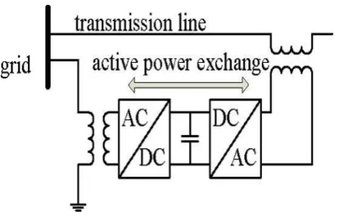
[image:1.595.308.550.219.375.2]Flexible ac Transmission Systems (FACTS) devices are used to control power flow in the transmission grid to relieve congestion and limit loop flows [1]. All electrical devices are prone to failure or malfunction when exposed to one or more power quality problems [2]. A power quality problem can be defined as any problem is manifested on voltage, current, or frequency deviation that results in power failure [3]. To control power flow, it is necessary to be able to maintain or change line impedances, bus voltage magnitudes, or phase angle differences. To control the power flow UPFC is the most powerful FACTS device, which can simultaneously control all the parameters of the system. The cost of the UPFC is high because UPFC handle the voltages and currents with high rating.
Fig -1: Simplified representation of UPFC
The UPFC is the combination of a static synchronous compensator (STATCOM) and a static synchronous series compensator (SSSC), which are coupled via a common dc link [4]. Due to the common dc-link interconnection, a failure that happens at one converter will influence the whole system, which reduces the reliability of the system. Due to lower reliability and higher cost the UPFC has not been commercially used, even though, it has the most advanced control capabilities.
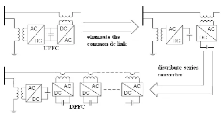
In this paper, the UPFC is further developed into a new FACTS device that is Distributed Power Flow Controller (DPFC), by applying the two approaches i.e., eliminating the common DC link and distributing the series converter. Within the DPFC, the common dc link between the shunt and series converters is eliminated, which provides flexibility for independent placement of series and shunt converter [5].
[image:1.595.335.532.645.727.2]© 2017, IRJET | Impact Factor value: 5.181 | ISO 9001:2008 Certified Journal
| Page 1505
Fig -3: Configuration of DPFC from UPFCDistributed power flow controller having two major advantages over Unified power flow controller: 1) The cost of DPFC is low because of the low component rating of the series converter and low voltage isolation, and 2) The reliability of the DPFC is high due to elimination of d.c. link between series and shunt converters.
In this work, the DPFC is used to mitigate the voltage sag and harmonics in three different cases. Line to ground, Line to line and 3-phase to ground faults are created to establish voltage sag and harmonics in the system and DPFC is used to mitigate both the problem.
2. DPFC CONSTRUCTION
The DPFC is derived from the UPFC by considering two approaches as follows. First, eliminating commonly connected dc link of UPFC [6] and the second is distributing series converter with D-FACTS concept to series converter, which consists of multiple units that are connected in series with the transmission lines as shown in figure.2.
The unique control capability of the UPFC is due to the back-to-back connection between the shunt and series converters, which allows the active power to freely exchange. In DPFC the active power exchange between converters with an eliminated DC link is provided through the transmission line present between the AC ports of the shunt and the series converters.
3. RELATED WORK
Distributed Power Flow Controller developed by eliminating the common DC link and distributing the series converter, which is based upon Distributed static series compensator concept. Both the concepts are explained below-
3.1 Elimination of D.C. link
Within the DPFC, the transmission line is used as a connection between shunt converter output and AC port
[image:2.595.310.556.187.374.2]of series converters, instead of using DC-link for power exchange between converters [7]. The active power exchange in DPFC is based on non-sinusoidal voltage and current, which can presented as the sum of sinusoidal components at different frequencies. It is the main result of Fourier analysis.
Fig - 4: Active power exchange between DPFC converters
The power supply generates the active power and the shunt converter absorbs it in fundamental frequency of current. Meanwhile, the third harmonic component is trapped in Y-Δ transformer [8]. The third harmonic current is injected into the neutral of Δ-Y transformer through the output terminal of the shunt converter. This harmonic current controls the dc voltage of series capacitors. According to the amount of required active power at the fundamental frequency, the DPFC series converters generate a voltage at the harmonic frequency, thereby absorbing the active power from harmonic components. At the receiving end transformer a high pass filter is connected, which is used to blocks the fundamental frequency components and allows the harmonic components to pass. High pass filter provides a return path for the harmonic component.
3.2 Distributed static series compensator
© 2017, IRJET | Impact Factor value: 5.181 | ISO 9001:2008 Certified Journal
| Page 1506
[image:3.595.316.559.100.259.2]voltage isolation is not required because converters are hanging on the line.
Fig - 5: D-FACTS unit configuration
Most of the voltage injected by a DSSC unit is in quadrature with the line current, to emulate inductive or capacitive impedance. A small part of the voltage is in phase with the line current and serves to self-power of DSSC unit. The DSSC is remotely controlled via wireless communication or a PLC (Power Line Communication). Rating of the device is very low (in the range of 10-20 KVA).
To control the transmission line, number of DSSC devices need to be attached to the line as per the requirement. At the highest level, DSSC can maximize the utilization of asset, reduction in congestion of system, available transfer capacity (ATC) of the system, enhance system reliability and capacity under contingencies, enhance system stability and can do so with lower capital and operating cost than most conventional single-point ‘lumped’ solutions, such as FACTS devices.
As shown in Fig. 5, Single Turn Transformer (STT) with a NC (normally closed) switch which makes the device in bypass condition until the inverter is activated. The dc control power supply transformer is excited by the current that flows in the STT secondary winding. As the switch is opened, DC bus of the inverter charged up and operation of inverter is initiated.
4. CONTROL STRATEGY OF DPFC
[image:3.595.54.269.136.285.2]The DPFC system consists of two types of converters, and each type of converter requires a different control scheme. The DPFC has three control strategies: central controller, series control and shunt control. The shunt and series control are local controllers and are responsible for maintaining their own converters parameters.
Fig - 6: DPFC control structure
4.1 Central control
The central controller manages all the series and shunt controllers and sends reference signals to both of them. According to the system requirement it gives corresponding reactive current signal for the shunt converter and voltage reference signals for the series converters. Central controller gives all the reference signals at the fundamental frequency.
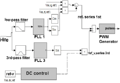
4.2 Series control
Each single-phase converter has its own series control through the line. This controller inputs are series capacitor voltages, line current and series voltage reference in dq-frame. Any series controller has one low-pass and one 3rd-pass filter to create fundamental and third harmonic current respectively. Two single-phase phase lock loop (PLL) are used to take frequency and phase information from network. The simulated diagram of series controller is shown in Fig.7.
[image:3.595.310.556.558.729.2]© 2017, IRJET | Impact Factor value: 5.181 | ISO 9001:2008 Certified Journal
| Page 1507
4.3 Shunt controlThe shunt converter is controlled to inject a constant 3rd harmonic current into the transmission line, which is intended to supply active power for the series converters. The shunt converter extracts some active power from the grid at the fundamental frequency to maintain its dc voltage.
The dc voltage of the shunt converter is controlled by the d
component of the current at the fundamental frequency,
and the q component is utilized for reactive power
compensation. The series converters generate a voltage with controllable phase angle at fundamental frequency,
and use the voltage at the 3rd frequency to absorb active
[image:4.595.309.562.176.329.2]power to maintain its dc voltages at a constant value. The power flow control function is realized by an outer control loop, the power flow control block. This block gets its reference signals from the system operator, and the control signals for DPFC series converters are sent remotely via wireless or PLC communication method.
Fig - 8: Shunt control configuration: (a) for fundamental frequency (b) for third-harmonic frequency
5. SIMULATION
The simulation of the DPFC has been done in Matlab/simulink environment, which is shown in Fig. 9. The DPFC model is simulated with a three phase source, which is connected to a non-linear load. The three phase source is connected to the load through parallel transmission lines(line 1 and line 2) with the same length. The series converter of DPFC is distributed through the line 2 and the shunt converter of DPFC is connected to the line 2 and ground through a Y-Δ three-phase transformer. For examine the performance of DPFC, a fault is created near the load. The result analysis have been done in three
[image:4.595.36.285.358.568.2]different cases. In case 1 single line to ground fault is considered, in case 2 line to line fault is considered and in case 3 three phase to ground fault is considered. The time duration of fault is 0.1 seconds (200-300 millisecond). The simulation parameters is listed in table 4.
Fig - 9: Simulation model of DPFC
6. SIMULATION RESULTS AND DISCUSSION
[image:4.595.312.555.413.543.2]Case-A: Single line to ground fault
Fig - 10: Load voltage waveform without DPFC
[image:4.595.319.549.583.728.2]© 2017, IRJET | Impact Factor value: 5.181 | ISO 9001:2008 Certified Journal
| Page 1508
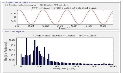
Fig - 12: Load voltage waveform with DPFCFig - 13: Load voltage THD with DPFC
[image:5.595.45.281.250.390.2]Case-B: Line to line fault
Fig - 14: Load voltage waveform without DPFC
Fig - 15: Load voltage THD without DPFC
[image:5.595.317.547.452.556.2]Fig - 16: Load voltage waveform with DPFC
Fig - 17: Load voltage THD with DPFC
[image:5.595.46.277.454.557.2]Case-C: Three phase to ground fault
Fig - 18: Load voltage waveform without DPFC
[image:5.595.320.548.592.735.2]© 2017, IRJET | Impact Factor value: 5.181 | ISO 9001:2008 Certified Journal
| Page 1509
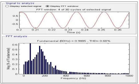
Fig - 20: Load voltage waveform with DPFCFig - 21: Load voltage THD with DPFC
7. COMPARATIVE ANALYSIS OF RESULT
[image:6.595.50.274.235.371.2]When any type of fault is occurred in the transmission line then parameters of the line gets affected. During fault condition the problem of voltage sag, current and increase in harmonics occurred. Without using any compensation these problems will remains in the system. After implementation of DPFC in the system the above problems are mitigated. The comparative analysis is done on the following three cases.
Table -1: Comparative analysis for single line to ground fault
Without DPFC With DPFC
Phases (THD) Voltage
sag (THD) sag Voltage
Phase A
3.18 %
0.50 P.U.
0.25 %
Nominal
Phase B 0.75 P.U. Nominal
Phase C Nominal Nominal
Table -2: Comparative analysis for line to line fault
Without DPFC With DPFC
Phases (THD) Voltage
sag (THD) sag Voltage
0.60 P.U. Nominal
Phase A 6.28
% 0.69 %
Phase B 0.35 P.U. Nominal
Phase C Nominal Nominal
Table -3: Comparative analysis for three phase to ground fault
Without DPFC With DPFC
Total harmonics
distortion
(THD)
Voltage sag Total
harmonics distortion
(THD)
Voltage sag
6.28 % 0.4 P.U. 0.68 % Nominal
8. CONCLUSIONS
In this study, the application of DPFC as a new FACTS device, in the voltage sag mitigation of a system composed of a three-phase source connected to a non-linear load through the parallel transmission lines is simulated in Matlab/Simulink environment. The voltage dip is analyzed by implementing a fault close to the system load. To detect the voltage sags and determine the three single phase reference voltages of DPFC, the SRF method is used as a detection and determination method. The obtained simulation results show the effectiveness of DPFC in power quality enhancement, especially in sag mitigation. In this work the performance analysis of the distributed power flow controller is done in three different cases as below-
Case-A: Single line to ground fault
In this work, single phase to ground fault is
created with the help of MATLAB. When DPFC is not connected with the transmission line then the value of voltage sag is 0.5 per unit in phase A, which is completely mitigated when DPFC is connected with the transmission line.
Total harmonics distortion (THD) is also reduced
from 3.18% to 0.25% in line.
The voltage sag in this case is 50% of the nominal
voltage.
Case-B: Line to line fault
In this work, line to line fault is created with the
[image:6.595.34.295.568.680.2]© 2017, IRJET | Impact Factor value: 5.181 | ISO 9001:2008 Certified Journal
| Page 1510
In this case total harmonics distortion (THD) is
also reduced from 6.28% to 0.69% in line.
Case-C: Three phase to ground fault
In this work, three phase to ground fault is
created with the help of MATLAB. When DPFC is not connected with the transmission line then the value of voltage sag is 0.4 per unit in all the phases, Which is completely mitigated when DPFC is connected with the transmission line.
In this case total harmonics distortion (THD) is
[image:7.595.36.294.287.499.2]also reduced from 6.28% to 0.68% in line.
Table - 4: System Parameters
Parameters Rating
Source voltage 230 KV
Frequency 60 Hz
X/R 3
Transformer rating 100 MVA
Magnetization resistance 500 (P.U)
Magnetization inductance 500 (P.U)
Resistance per unit length of
line 0.01273
Inductance per unit length of
line 0.9337 mH
Capacitance per unit length of
line 12.74 nF
Length of line 100 Km
Snubber resistance 105 ohm
D.C link capacitance 25 x 10-3
Ground resistance 0.001 ohm
REFERENCES
[1] Deepak Divan and Harjeet Johal, “Distributed FACTS-
A new concept for realizing power flow control,” IEEE Transaction on power electronics, vol 22, no.6, p.p. 2253-2260, 2007.
[2] Kevin Kumar G. Raythaththa and Bhargav Y. Vyas,
“System parameters improvement of transmission line
using Distributedstatic Series Compensator (DSSC),”IE
EE International Conference on Energy Efficient
Technologies for Sustainability (ICEETS), p.p.
459-463, 2016.
[3] A.N.V.V. Rajasekhar and Naveen Babu, “Harmonics
reduction and power quality improvement by using DPFC,” International conference on Electrical, Electronics, and Optimization techniques, p.p. 1754-1758, 2016.
[4] Z. H. Yuan, S. W. H de Haan, B. Frreira, and D. Cevoric,
“A FACTS device: Distributed power flow controller (DPFC),” IEEE Transaction on Power Electronics, vol.25, no.10, p.p. 2564-2572, 2010.
[5] Y. Zhihui, S.W.H. de Haan, and B. Ferreira," DPFC
control during shunt converter failure,” IEEE conference in energy conversion congress and exposition, p.p. 2727-2732, 2009.
[6] K.venkata Nagaraju and N.C. Kotaian, “ Modeling And
Analysis Of Distributed Power Flow Controller Based On Reliability Of the Transmission System,” International Journal of Electrical, Electronics and Data Communication, vol. 1, 2013.
[7] Vinay Kumar Perumandla and D. Chandra Sheker, “ A
Modern Design For Power Quality Improvement Using Direct Power Flow Controller,” International Journal of Research Sciences and Advanced Engineering, vol. 2, p.p. 23-28, 2014.
[8] Ahmad Jamshidi, S. Masoud Barakati and M. Moradi
Ghahderijani, “Impact of Distributed Power Flow Controller to Improve Power Quality Based on Synchronous Reference Frame Method,” IACSIT International Journal of Engineering and Technology, Vol. 4, No. 5, 2012.
[9] CH. Ranga Rao, N. Hari Charan and K. Rajesh Babu,
“Modelling and simulation of DPFC system for power quality improvement,” International Journal of Electrical and Electronics Engineering Research (IJEEER), vol. 5, p.p. 61-66, 2015.
[10] Y. Sozer and D.A.Torrey, “Modeling and control utility
interactive inverters,” IEEE Transactions on power electronics, vol 24, no. 8, p.p. 2475-2483, 2009.
[11] J. Faiz, G.H. Shahgholian, and M. Torabian, “Design and
simulation of UPFC for enhancement of power quality in transmission lines,” IEEE international conference on power system technology, vol. 24, no. 4, p.p. 1-5, 2010.
[12] J. R. Enslin, “Unified approach to power quality
mitigation,” IEEE conference on Industrial Electronics (ISIE ’98), vol. 1, p.p. 8-20, 1998.
BIOGRAPHIES
Vikash Kumar Goutam received his B. Tech. degree in Electrical Engineering from MPEC Kanpur in 2006. Presently he is pursuing his M.Tech in Electrical Engineering (Power system) from KNIT, Sultanpur India.
Dr. Deependra Singh is currently working as a Professor in Electrical Engineering department in KNIT, Sultanpur, India. His area of
interest is Measurement &