Frontiers in Heat and Mass Transfer (FHMT), 6, 14 (2015) DOI: 10.5098/hmt.6.14
Global Digital Central ISSN: 2151-8629
NUMERICAL SIMULATION OF METAL-PLASTIC COMPOSITE HEAT
RADIATOR WITH HEMISPHERICAL MICROSTRUCTURE ARRAY
Hui Jiang
a,b, Daming Wu
a,b,c, Jian Zhuang
a,b*, Ying Liu
a,b,c, Changqing Huang
a,ba College of Mechanical and Electrical Engineering, Beijing University of Chemical Technology, Beijing, 100029, China b Polymer Material Processing Equipment Engineering Research Center of The Ministry of Education, Beijing , 100029, China c State Key Laboratory of Organic–Inorganic Composites, Beijing University of Chemical Technology, Beijing , 100029, China
ABSTRACT
A new type of metal-plastic composite heat radiator with hemispherical microstructure array was proposed in this paper. The influence of the geometrical parameters of the microstructure array, including size of the hemisphere, configuration of hemisphere, tilt angle of the radiator, thermal conductivity and radiation emissivity of the plastic, on the process of heat transfer under natural convectionwere numerically simulated. It was concluded that the metal-plastic composite heat radiator with hemispherical microstructure array had comparable heat transfer behaviors with those of metal heat radiator. So it is possible to replace metal heat radiator by such a metal-plastic composite heat radiator in case of high moisture or corrosion applications. Under the same volume, the cooling capacity of the heat radiator made of metal-plastic was 20 times as the heat radiator made of metal. The heat flux of plastic plate with hemispherical microstructure was superior to the ordinary flat plastic plate. And the former heat flux was
2050 W/m2, about two times as the latter, 1272W/m2. The optimal inclination angle of the heat radiator with maximum heater flux was around 45°.
Keywords: metal-plastic composite heat radiator; hemi-sphere microstructurearray; microstructure; numerical simulation
1. INTRODUCTION
With the development of Micro Electro Mechanical Systems (MEMS) and micro chemical mechanical system, the integration density of electronic device becomes higher. Power consumption and heat output was becoming more and more sophisticated, however, the size was becoming smaller and smaller and heat flux of the electronic device was increasing .In order to meet the requirements of the development of the electronics industry, including LED lamps and lanterns, compact, lightweight and highly efficient microstructure heat radiators are needed.
The cooling forms of microstructure heat radiator were summarized as natural convection and forced convection. Many people had done a lot of research on natural convection under different structure. Yu et al.(2010, 2011, 2012)investigated natural convection heat transfer around a radial heat radiator adapted for dissipating heat on a circular LED (light emitting diode) light and optimized the heat radiator. The numerical results were validated with experimental results and it showed a good agreement. Parametric studies were performed to compare the effects of the number of fins, long fin length, middle fin length and heat flux on the thermal resistance and average heat transfer coefficient. In addition, the effect of radiation on heat transfer was examined by varying emissivity, and it was found that the maximum radiation contribution was 27%. Xaman et al. (2008) presented a two-dimensional numerical study of combined heat transfer (laminar and turbulent natural convection, surface thermal radiation and conduction) in a square cavity with a glass wall.Results show that the flow pattern is not symmetric due to the combined effect of non-isothermal glass wall and radiative exchange inside the cavity. Tari et al.(2013), in order to obtain a validated model that is used for investigating inclined orientations of a heat sink, investigated the steady-state natural convection from heat radiators with parallel arrangement of rectangular cross section vertical plate fins on a vertical base
*Corresponding author. Email:[email protected]
numerically. Rao et al. (2006) solve the problem of natural convection heat transfer from a horizontal fin array by treating the adjacent internal fins as two-fin enclosures.The problem of natural convection heat transfer from a horizontal fin array is theoretically formulated by treating the adjacent internal fins as two-fin enclosures. Mueller et al.(2006)made the predictions and measurements of the temperature plate fins on a vertical base numerically. Rao et al. (2006) solved the problem of natural convection heat transfer from a horizontal fin array by treating the adjacent internal fins as two-fin enclosures. The comparison was made to experimental results, and the agreement between the model and experiment is very good. Results show that the heat loss due to radiation is typically 15–20% of the total. Lauriat (2006) studied numerically the heat transfer by natural convection and surface radiation in a two-dimensional vented enclosure in contact with a cold external ambient and a hot internal ambient by Lauriat (2006),and the interplay between convection and radiation was discussed and it was shown that radiation contribution in heat transfer dominated for all of the cases investigated. A comprehensive theoretical and experimental study was carried out on the thermal performance of a pin-fin heat sink by Kobus (2005). By the way of analyzing the theoretical model, the geometric factors had effects on the heat dissipation .And experiments were studied at this time, the results showed that the prediction model and experimental model had a good consistence. Kim et al. (2009) compare thermal performances of two types of heat sinks commonly used in the electronic equipment industry: plate-fin and pin-fin heat sink. Jang et al. (2012) optimized the cooling performance and mass of a pin-fin radial heat sink. The effects of various geometric parameters on the thermal resistance and mass of the heat sink were investigated; these indicated that the system was sensitive to the number of fin arrays, as well as the length of the long and middle fins. A systematic theoretical investigation of the effects of fin spacing, fin height, fin length and temperature difference between fin and surroundings on the free convection heat transfer from horizontal fin arrays was
Frontiers in Heat and Mass Transfer
possible to obtain optimum performance in terms of overall heat transfer by only concentrating on one or two parameters. To sum up, through the numerical simulation, the model and the experimental study, in the case of natural convection, geometric parameters, inclination angle, and the effects of surface radiation on heat dissipation were achieved.
In this paper, effects of heat transfer of the metal-plastic composite heat radiator with hemispherical microstructure array was studied, which included comparison of the materials used, comparison of the size of the geometric size, comparison of arrangement way, comparison of radiator angle, comparison of thermal conductivity of the conductive plastic, contrast of radiant emittance ofheat conduction plastic, contrast of different shape, and so on. According to the first type boundary condition, the heat flux was studied.
2. MATHEMATICAL MODE
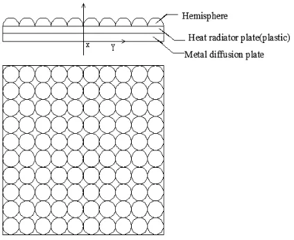
The metal-plastic composite heat radiator consists of metal diffusion plate and plastic heat radiator with hemispherical microstructure array, as shown in Fig.1.
Considering the first type of boundary condition, the heat generated by the heat source through the metal diffusion plate and plastic heat radiator, and then by natural convection, forced convection, and radiation spreads to the surrounding environment. Keeping surface temperature of heat source a constant, environmental temperature also keeps constant. When heat flux of heat source on the surface reaches a heat balance, the greater the heat flux, the better the heat transfer effect of the heat radiator.
According to above proposed physical model, a mathematical model is made and a numerical simulation for different shapes of metal-plastic composite microstructure is carried out.
The following assumptions are proposed for the mathematical model:
1) The metal and plastic materials are isotropic.
2) The contact thermal resistance between metal and plastic layer is not considered.
3) The viscous dissipation of the air is ignored, and the air flow is laminar at steady state.
4) Only the changes in air density caused by floating force are considered.
5) The changes of heat transfer law caused by micro scale effect are not considered.
Fig. 1Schematic of a metal-plastic composite heat radiator with hemisphere microstructure array
diffusion layer, plastic layer, finally the microstructure to strengthen heat transfer effect, is spread to the air.
3. GOVERNING EQUATIONS
3.1 In the air:
Continuity equation:
0
x y z
ρμ ρν ρ
∂ +∂ +∂ =
∂ ∂ ∂
w
(1)
Momentum equation in x direction:
2 2 2
2 2 2
( ) ( ) ( )
u∂ ρμ + ∂ρμ + ∂ρμ = −∂ +μ(∂ +∂ +∂ )- gρ
∂ ∂ ∂ ∂ ∂ ∂ ∂
p u u u
v w
x y z x x y z (2)
Momentum equation in y direction:
2 2 2
2 2 2
( ) ( ) ( )
u∂ρ + ∂ ρ + ∂ρ = −∂ +μ(∂ +∂ +∂ )
∂ ∂ ∂ ∂ ∂ ∂ ∂
v v v w v p v v v
x y z y x y z (3)
Momentum equation in z direction:
2 2 2
2 2 2
(ρ ) (ρ ) (ρ ) μ( )
∂ + ∂ + ∂ = −∂ + ∂ +∂ +∂
∂ ∂ ∂ ∂ ∂ ∂ ∂
v v v p v v v
u v w
x y z z x y z (4)
Energy equation:
2 2 2
2 2 2
( )
λ ρ
∂ + ∂ + ∂ = ∂ +∂ +∂
∂ ∂ ∂ ∂ ∂ ∂
a a a a a a
p
T T T T T T
u v w
x y z c x y z (5) where the air is incompressible, the density difference of the air is proportional to the temperature difference.
ρ ρ= ∞[1−β(T T− ∞)] (6) where ρ∞ is the density which corresponds to T∞, and β is the volume expansion factor.
3.2 In the solid
3.2.1 Energy equation:
Heat conduction equation from heat source to the metal diffusion plate is as follows:
λ
= − m
m dT
Q A
dx
(7) where Q is the heat that is generated by the heat source,λmis coefficient of thermal conductivity of the metal, A is the heat dissipation area, and Tm is the temperature of the metal along the x direction.
In the same way,heat conduction equation from the metal diffusion plate to the plastic heat base is as follows:
−λ m = −λ P m P
dT dT
A A
dx dx (8) whereλPis coefficient of thermal conductivity of the plastic,Tp is the temperature of the plastic along the x direction.
In addition, heat conduction equation from the plastic heat radiator to the air is as follows.
λ ( ) σ ε ( 4 4)
− P = − + −
P t e e f e t e f dT
A h A T T A T T
dx (9)
where ht is the total convection heat transfer coefficient, Ae is the expanded surface area, Te is the temperature of the microstructure surface, and Tf is the temperature of the air.
3.2.2 The boundary conditions
:
Frontiers in Heat and Mass Transfer (FHMT), 6, 14 (2015) DOI: 10.5098/hmt.6.14
Global Digital Central ISSN: 2151-8629
( , , ) ( , , )
( , , ) | = ( , , ) | , |−λ ∂ = −λ ∂ |
∂ ∂
p m
p cs m cs p cs m cs T x y z T x y z T x y z T x y z
n n (10) The boundary condition between the surface of the plastic
microstructure and air is as follows:
4 4
( , , )
-λ ∂ = ( − )+σε( − )
∂ p
p t e f t e a T x y z
h T T T T
n
(11)
Equations(1-11)are the model that is used to solve the convective
heat transfer of air flow and solid internal heat conduction. Based on the mathematical model, we can solve the heat dissipation problem of composite microstructure heat radiator using the FloEFD software.
4. NUMERICAL SIMULATIONS
In this paper, the finite element software FloEFD9.0 is used for numerical simulation. By inputting Pro/E drawings of heat sink of different size and structure into the FloEFD software, and then conducting numerical simulation, a variety of graphs and numerical values of different physical quantities are presented. For hemispherical metal - plastic composite microstructure heat radiator in this paper, there are four kinds of arrangement mode, which are regular hexagon, regular triangle, square, square closely (Fig.2). The numerical simulations of the four arrangement mode of heat radiator are done in this paper. The boundary condition is the first type of boundary condition, that is, the temperature of the heat source is a constant value. Making the heat flux of heat source as the goal, the greater its value is, the better the overall heat radiator cooling effect is. Physical parameters of the different materials are shown in table 1.The heat flux of heat radiator is obtained from equation 12.
4 4
( ) σε( )
= t e− f + t e − a
q h T T T T (12)
where q is heat flux through surface of the heat source, ht is the equivalent for the surface heat transfer coefficient of the overall heat radiator, εt is equivalent for the radiation emissivity of the overall heat radiator, Tf is the temperature of the air on the surface of the heat radiator, and Ta is environment temperature. Generally in this paper: Tf = Ta =25℃.
Fig. 2 Four kinds of arrangement of hemisphere (a) hexagonal (b) square(c) triangle (d) square closely
Table1 Overall heat radiator size parameters (mm)
No. parameters size 1 Thickness of metal diffusion plate 0.5
2 Thickness of the heat radiator plate 0.5
3 Metal and the heat radiator plate size 10×10
4 Geometric size of the hemisphere 0.5
Table 2 Physical parameters of different materials Material
Parameters
Aluminum
6061 PPS Air
Density (Kg/m3) 2688.9 1800 1.205
Specific heat
(J/Kg·K) 902 1100 1006.43
Thermal conductivity (W/(m·K))
237 20 0.02637
4.1 The influence on the whole flux of changing material
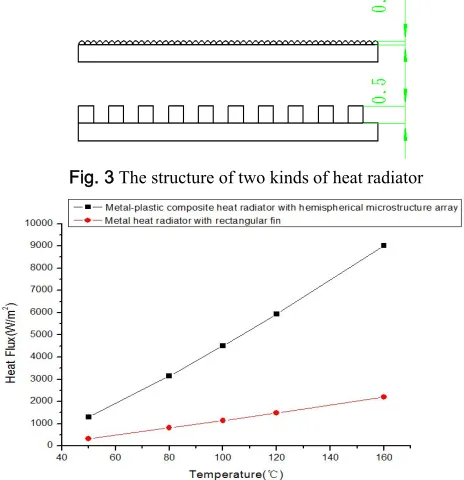
The material of heat radiators is Al and PPS, respectively. The overall heat radiator size parameters are in Fig. 3. The volume of metal heat radiator with rectangular fins is five times as metal-plastic composite heat radiator with hemispherical microstructure array. In this paper, two kinds of heat radiator are studied together. Under the same condition (the first type of boundary condition), we could have the results in Fig.4.The X axis is the temperature of surface of the heat source. The Y axis is the overall surface heat flux. The red dot curve is on behalf of the heat radiator Al-Al (The material of heat radiator is Al). And the black square dot curve is on behalf of the heat radiator is Al-PPS (The material of heat radiator is PPS). With the surface temperature rising, the heat flux is also a linear upward trend from the Fig.4 .In contrast, the heat flux in the form of Al - PPS is higher than that in the form of Al - Al. The reason is that radiation emission rate (0.98) of the PPS is higher than that of Al (0.1).The heat dissipation of the former by radiation is higher than the latter, thus the heat flux is higher than the latter. In addition, you can see that PPS could take the place of Al as the heat radiator. And we could conclude, under the same volume, the cooling capacity of the metal-plastic composite heat radiator with hemispherical microstructure array is about 20 times as metal heat radiator with rectangular fins. Because the plastics have large surface area, corrosion resistance, light weight, low manufacturing cost and easy processing, etc. So the metal - plastic composite microstructure heat radiator has a much broader use space.
Fig. 3 The structure of two kinds of heat radiator
4.2 The influence on the overall heat flux of changing
hemisphere arrangement mode
Hemispherical arrangement influences the surface area and the thermal performance of the heat radiator further. Hemispherical arrangement mode includes regular triangle, square, square closely and regular hexagon. From the Fig.5, it can be seen that as temperatures rise, the trend of the heat flux is also rising and the higher the temperature, the faster the change of heat flux. Since the arrangement of hemisphere is compact, it could be seen that the heat flux changes among them are very small. When the temperature is 150。
C, heat flux approached 4000W/m2. And at this time the square closely arrangement mode has the highest heat flux. The reason is that the square closely arrangement mode is the most compact. So it has the highest surface heat flux.
Fig. 5 The influence of four kinds of arrangement for heat flux
4.3The influence on the overall heat flux of adding
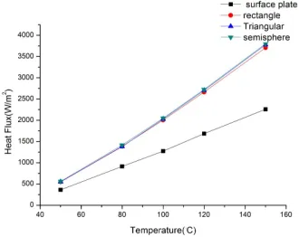
different microstructure on the surface
From Fig. 3, by adding the microstructure on the surface, the surface area of the heat radiator is increased, which has influences on the heat dissipation of the heat radiator. As shown in Fig.6, the black square represents heat flux curve without adding microstructure. Red circle represents heat flux curve with the rectangular groove microstructure. Blue upward triangle represents heat flux curve with adding a regular triangle groove microstructure. Green downward triangle represents heat flux curve with adding hemispherical microstructure. As shown clearly in Fig.6, the heat flux of the heat radiator by adding the microstructure is greater than heat radiator without adding the microstructure. The reason is that increasing the surface area of heat radiator by adding microstructure, which makes the heat radiator more compact, makes the cooling capacity greater. So the performance of heat dissipation is increased. Among the rectangular groove, triangular groove and hemispherical microstructure, although
Fig. 6 Contrast among surface plate,triangular groove,rectangular groove,and hemispherical microstructure
their differences of numerical results are very small, it increases with the rising of the temperature.
4.4 The influence on the overall heat flux of changing
thermal conductivity of the plastic
According to the first type of boundary condition ,the temperature of the heat source is 100℃, and the temperature of environment temperature is 25°C.The heat flux of the heat radiator changing with the thermal conductivity of plastic is presented in Fig.7.From 5W/m·K-50W/m·K, the heat flux is linear to the thermal conductivity of plastic. And when the thermal conductivity is greater than 50 W/m·K, the heat flux variation is small and heat flux basically reached its maximum 2930W/m2. That is to say, when the thermal conductivity reaches 50W/m·K, the modification by adding filler material to increase the heat flux is meaningless. We need to seek other ways to make heat radiator improved and enhanced.
Fig. 7 The heat flux with the change of thermal conductivity
4.5The influence on the overall heat flux of different
radiation emissivity
According to the first kind of boundary condition, the temperature of the heat source is 100℃, and the temperature of environment temperature is 25℃. We can see heat flux curve with the change of the different radiation emissivity in Fig.8. In general, the bigger the radiation emissivity is, the greater the heat flux is. The overall heat flux increases with the radiation emissivity rising. And at the initial stage (0-0.25), heat flux increases with the the radiation emissivity linearly. Afterwards it reaches a stable phase (0.25- 0.75), although the radiation emission rate increases, the heat flux dose not increase. Finally with the increasing of the radiation emissivity (0.75- 0.98), heat flux increases linearly again.
Frontiers in Heat and Mass Transfer (FHMT), 6, 14 (2015) DOI: 10.5098/hmt.6.14
Global Digital Central ISSN: 2151-8629
4.6 Influence on the overal heat fiux of geometric size of
hemisphere
Particle size of the hemisphere has certain effects on heat flux in the Fig.9. When the particle size from 0.5 mm to 2 mm, the change of heat flux is not obvious, that is to say, the size of the particle size has no obvious efffects on heat flux. But from 2 mm to 5 mm, the heat flux has apparent change. And as temperature rises, the difference is more and more obvious.The reason is due to the decrease of the particle size and increase of the surface area of the heat dissipation, and then it has influence on heat flux. Reducing the size of the particle size further can make the heat flux bigger. But it is limited to computer level, so further simulation is not going on in this paper.
Fig. 9 The heat flux with changing the particle size
4.7 Influence on the overall heat flux of inclination angle
Because of the natural phenomena of the natural convection, hot air is always to rise. So the inclination angle of the heat radiator has certain effects on heat flux. In this paper,we get five points from 0 - 180°, that is 0°, 45°, 90°, 135°,180°. From Fig. 10, you can see from the angle of 0° to 45°, the trend of the heat flux is slowly rising. And there is a peak around 45°,that is, 2059 W/m2. From 45° – 180°, the heat flux has a tendency to fall sharply. And from high to low, heat flux changes is about half of their original value. Therefore in the process of actual situations, we should pay attention to inclination angle. Angle should be around 45°, and the greatest cooling effect can be achieved.
Fig. 10 The heat flux with the angle of inclination
Figures 11 shows velocity vector diagrams of angle of 0°, 90°, and 180°, respectively. As shown in the figure, with the changes of Angle, the velocity vector changes as well. Around the radiator, the size , direction of the velocity vector and the compact degree will also be affected. The compact degree of angle of 0° is higher than 90°
and 180°. Therefore, the heat flux of the former is higher than the latter.
a (0°)
b (90°)
c (180°)
5. CONCLUSIONS
A new type of metal-plastic composite heat radiator with hemisphere microstructure array is put forward. And the different structure parameters and physical parameters of heat radiator are simulated. We get the following conclusion: The metal-plastic composite heat radiator with hemispherical microstructure array can completely replace the metal heat radiator with rectangular fins. The cooling capacity of the metal-plastic composite heat radiator with hemispherical microstructure array is about 20 times as metal heat radiator with rectangular fins. In some situations, and the former was easier to be machined, cheaper, anticorrosion and lighter than the latter. By adding the hemisphere microstructure on the surface, it could increase the surface area. Compared with the ordinary surface plate heat radiator, when to achieve heat balance, the former can achieve greater heat flux. Compared with micro triangle groove and micro rectangular groove, the heat flux of the hemispherical microstructure heat radiator is slightly larger. With the increasing of thermal conductivity of the heat radiator, heat flux grows lineally at the initial stage. There is a value around 50 W/m·K, after which heat flux is almost the same. With the changes of radiation emissivity of the plastic, heat flux grows lineally at the initial stage. There is a value around 0.25, after which, heat flux remains almost the same. Again there is a value around 0.75, after which, heat flux continues to grow linearly. The geometric size of hemisphere has influences on heat flux. And with the increase of geometric size of the hemisphere (0.5mm-2mm-5mm), the overall heat flux of heat radiator becomes smaller. The inclination of heat radiator has influences on heat flux. There is a peak around 45°, before which, heat flux increases linearly, and after which, heat flux decreases sharply.
ACKNOWLEDGEMENTS
The authors would like to express gratitude to the National Natural Science Foundation of China Youth Science Fund (No. 51203010)
NOMENCLATURE
T temperature (K)
cp coefficient of heat capacity (J/Kg·K)
u x-component of velocity (m/s) v y-component of velocity (m/s) w z-component of velocity (m/s) g acceleration of gravity (m/s2) h convection coefficient (W/m2·K) q heat flux (W/m2)
Greek symbols
λ thermal conductivity (W/m·K)
ρ air density (Kg/m3)
μ the dynamic viscosity of air (N/m2·s)
ε radiation emissivity Subscripts
Cs contact surface n along the gradient direction m metal
p plastic e expanded
∞
at infinity 0 initial condition a ambient f fluid t totalREFERENCES
Jang, D., S.H. Yu and K.S. Lee, 2012, “Multidisciplinary Optimization of a Pin-Fin Radial Heat Sink for Led Lighting Applications,” International Journal of Heat and Mass Transfer, 55, 515-521.
http://dx.doi.org/10.1016/j.ijheatmasstransfer.2011.02.012
Kobus, C. J., and T. Oshio,2005, “Development of a Theoretical Model for Predicting the Thermal Performance Characteristics of a Vertical Pin-Fin Array Heat Sink under Combined Forced and Natural Convection with Impinging Flow, ”International Journal of Heat and Mass Transfer, 48, 1053-1063.
http://dx.doi.org/10.1016/j.ijheatmasstransfer.2004.09.042
Kim, D.K., S, J.K., and J.K. Bae. 2009, “Comparison of Thermal Performances of Plate-Fin and Pin-Fin Heat Sinks Subject to an Impinging Flow,” International Journal of Heat and Mass Transfer,
52, 3510-3517.
http://dx.doi.org/10.1016/j.ijheatmasstransfer.2009.02.041
Lauriat, G., and G. Desrayaud, 2006, “Effect of Surface Radiation on Conjugate Natural Convection in Partially Open Enclosures,” International Journal of Thermal Sciences, 45, 335-346.
http://dx.doi.org/10.1016/j.ijthermalsci.2005.07.002
Mueller, D.W., and H.I. Abu-Mulaweh, 2006, “Prediction of the Temperature in a Fin Cooled by Natural Convection and Radiation,” Applied Thermal Engineering, 26, 1662-1668.
http://dx.doi.org/10.1016/j.applthermaleng.2005.11.014
Rao, V., Dharma, S. V., Naidu, B., Govinda, R.,and K. V. Sharma, 2006, “Heat Transfer from a Horizontal Fin Array by Natural Convection and Radiation—a Conjugate Analysis,” International Journal of Heat and Mass Transfer, 49, 3379-3391.
http://dx.doi.org/10.1016/j.ijheatmasstransfer.2006.03.010
Senol Baskaya., M, S., Murat, O., 2000, “Parametric Study of Natural Convection Heat Transfer from Horizontal Rectangular Fin Arrays,” International Journal of Thermal Sciences, 39, 797–805
http://dx.doi.org/10.1016/S1290-0729(00)00271-4
Tari, I., and Mehdi, M., 2013, “Natural Convection Heat Transfer from Inclined Plate-Fin Heat Sinks,” International Journal of Heat and Mass Transfer, 56, 574-593.
http://dx.doi.org/10.1016/j.ijheatmasstransfer.2012.08.050
Xamán, J., J. Arce, Álvarez, G. and Chávez, Y., 2008, “Laminar and Turbulent Natural Convection Combined with Surface Thermal Radiation in a Square Cavity with a Glass Wall,” International Journal of Thermal Sciences, 47, 1630-1638.
http://dx.doi.org/10.1016/j.ijthermalsci.2008.01.012
Yu, S.H., Lee, K.S., and Yook, S.J., 2010, "Natural Convection around a Radial Heat Sink," International Journal of Heat and Mass Transfer, 53, 2935-2938.
http://dx.doi.org/10.1016/j.ijheatmasstransfer.2010.02.032
Yu, S.H., Lee, K.S., and Yook, S.J., 2011, "Optimum Design of a Radial Heat Sink under Natural Convection,"International Journal of Heat and Mass Transfer, 54, 2499-2505.
http://dx.doi.org/10.1016/j.ijheatmasstransfer.2011.02.012
Yu, S.H., Jang, D., and Lee, K.S., 2012, "Effect of Radiation in a Radial Heat Sink under Natural Convection," International Journal of Heat and Mass Transfer, 55, 505-509.