Volume: 03, Issue: 01
(JANUARY
–
FEBRUARY, 2017)
16
Simulation Analysis of FACTs Devices for Transient Stability Improvement in
Multi Machine System
Kunal Gupta1, Prof. Yogesh Pahariya2
Department of Electrical and Electronics Engineering RKDF College of Engineering Bhopal
Abstract:- Transient stability control plays an important role in ensure the stable operation of power systems in the experience of large disturbances and faults, and is thus an important area of research. This paper investigates relationship of SVC, STATCOM and UPFC performance for the transient stability improvement of the power system. The enhancement of transient stability of the power system, using SVC (Static VAR Compensator), STATCOM (Static Synchronous Compensator) and UPFC (Unified Power Flow Controller) which is an effective FACTS (Flexible AC Transmission System) device able of controlling the active and reactive power flows in a transmission line by controlling appropriately parameters. Simulations are carried out in Mat lab/ Simulink environment. The presentation of SVC, STATCOM& UPFC is compared from each other. So for the improvement of transient stability STATCOM is superior to SVC. The simulation results demonstrate the value and robustness of the proposed STATCOM, UPFC& SVC on transient stability improvement of the system.
Keywords: FACTS, SVC, STATCOM, UPFC, Mat lab /
Simulink, Transient stability.
I. INTRODUCTION
Modern power system is a difficult network comprise of numerous generators, transmission lines, variety of loads and transformers. As an effect of increasing power demand, some transmission lines are more loaded than was intended when they were built. With the increased loading of long transmission lines, the difficulty of transient stability after a major fault can become a transmission limiting factor [1]. Now power engineers are much more afraid about transient stability problem due to blackout in northeast United States, Scandinavia, England and Italy. Transient stability refers to the ability of a system to maintain synchronous operation in the event of large disturbances such as multi-phase short-circuit faults or switching of lines [2]. The resulting system answer involves large excursions of generator rotor angles and is influenced by the nonlinear power angle relationship. Stability depends ahead both the initial operating conditions of the system and the severity of the disturbance. Latest development of power electronics introduces the use of flexible ac transmission system (FACTS) controllers in power systems. FACTS controllers are able of controlling the network condition in a very fast manner and this feature of FACTS can be exploited to improve the voltage stability, and steady state and transient stabilities of a difficult power system [3-4]. This allows increased utilization of existing network closer to its thermal loading capacity, and thus avoiding the require
to construct new transmission lines. Static VAR Compensator (SVC) is a first generation FACTS device that can control voltage at the required bus thereby improving the voltage profile of the system. The main task of an SVC is to maintain the voltage at a particular bus by means of reactive power compensation (obtained by varying the firing angle of the thyristors) [5]. SVCs have been use for high performance steady state and transient voltage control compared with standard shunt compensation. SVCs are also used to dampen power swings, improve transient stability, and decrease system losses by optimized reactive power control [6-7].STATCOM, a shunt compensation device, from the family of flexible alternating current transmission systems (FACTS). The STATCOM is a solid-state voltage source converter which is tied to a transmission line. A STATCOM injects an almost sinusoidal current, of changeable magnitude, at the point of connection. This injected current is approximately in quadrature with the line voltage, thereby emulating an inductive or a capacitive reactance at the point of connection with the transmission line. The profit of utilizing FACTS devices in electrical transmission systems can be summarize as follows:
1. Better utilization of presented transmission system assets
2. improved transmission system reliability and availability
3. Increased dynamic and transient grid stability and decrease of loop flows
4. Better quality of supply for sensitive industries Environmental profit.
Volume: 03, Issue: 01
(JANUARY
–
FEBRUARY, 2017)
17 bus, where the SVC is connected, is maintained at the reference value.
Figure 1: Static VAR Compensator (SVC)
III. STATIC SYNCHRONOUS COMPENSATOR
The STATCOM is based on a solid state synchronous voltage source which generates a objective set of three sinusoidal voltages at the fundamental frequency with quickly controllable amplitude and phase angle. The relationship of a line voltage, thereby emulating an inductive or a capacitive reactance at the position of connection with the transmission line. STATCOM is shown in Figure 2.Figure 2: Static Synchronous Compensator (STATCOM)
IV. UNIFIED POWER FLOW CONTROLLER
Unified power flow control is a apparatus nothing but a combination of series & shunt facts device & it clearly do the same work what is done by the series & shunt fact device alone. It is the most influential facts device [7]. UPFC is mainly a combination of SSSC & STATCOM. Used to advance the transient stability of the power system [8].The schematic figure of unified power flow controller is given below.V. SIMULATION MODEL AND RESULTS
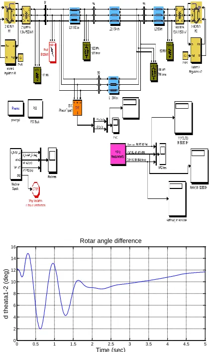
All the FACTs devices like SVC, STATCOM and UPFC are compared with the simulation analysis in MATLAB simulink.5.1 IMPACT OF SVC (LLL-G FAULT)
When apply a 3-phase fault and observe that impact of the SVC for stabilizing the network for the period of a severe possibility. First put the two PSS in service. Reprogram the Fault Breaker of simulation block to apply a
3-phase-to-ground fault. Verify that the SVC is in fixed susceptance mode with Bref = 0, the rating of the SVC is +/-200MVA
when at the Start of simulation. By looking at the d_theta1_2 signal, you must observe that the two machines quickly drop out of synchronism after fault clearing.
Figure 3: Unified Power Flow Controller (UPFC)
In order not to track pointless simulation, the Simulink Stop block is used to stop the simulation when the angle difference reaches 3*360 degrees at this time open the SVC block menu and change the SVC mode of procedure to Voltage regulation. The SVC will now attempt to take the voltage by injecting reactive power on the line when the voltage is lesser than the reference voltage (1.0 pu). The selected SVC reference voltage corresponds to the bus
0 0.5 1 1.5 2 2.5 3 3.5 4 4.5 5 0
2 4 6 8 10 12 14 16
Time (sec)
d
the
at
a1
-2
(de
g)
Volume: 03, Issue: 01
(JANUARY
–
FEBRUARY, 2017)
18 voltage with the SVC out of service. In steady state the SVC will therefore be balanced and approaching up for voltage compensation when voltage departs from its reference set point. Let we installed SVC at bus 2, and 3-phase fault at same place as shown in fig. 5.1.
5.2 IMPACT OF STATCOM (LLL-G FAULT)
The Static Synchronous Compensator (STATCOM) is single of the input FACTS devices. STATCOM output current (inductive or capacitive) be able to controlled self-determining of the AC system voltage.
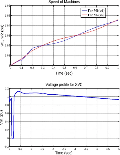
Fig.5.1 Waveforms for SVC with 3-Phase (LLL-G) Fault, (a) Rotor angle difference, (b) Speed of machines, (c) Voltages profile, (d) Reactive power profile.
The power grid consists of two 500-kV equivalents transmission line. The STATCOM is located at bus B2 and has a rating of +/- 200MVA. This STATCOM is a phasor model of a typical three-level PWM STATCOM. but you release the STATCOM block and select "Display Power data", you will monitor that our model represent a
STATCOM having a DC link nominal voltage of 40 kV with an equivalent capacitance of 375 µF. On the AC side, its total equivalent impedance is 0.22 pu on 200 MVA.
Table 5.1 Reactive power & voltages with SVC Bus Q (Mvar) V (k volts)
B1 591.6 464.7
B2 13.11 464.4
B3 -559.3 437.1
B4 -371.5 391.1
This impedance represents the transformer leakage reactance and the phase reactor of the IGBT bridge of an actual PWM STATCOM. Simulation is showing in below for STATCOM with 3-phase fault (LLL-G).
0 0.1 0.2 0.3 0.4 0.5 0.6 0.7 0.8 0.9 1
1 1.01 1.02 1.03 1.04 1.05 1.06
Time (sec)
w
1,
w
2
(pu
)
Speed of Machines
For M1(w1) For M2(w2)
0 0.5 1 1.5 2 2.5 3 3.5 4 4.5 5
-0.2 0 0.2 0.4 0.6 0.8 1 1.2
Voltage profile for SVC
Time (sec)
Vm
(pu
)
0 0.5 1 1.5 2 2.5 3 3.5 4 4.5 5
-1.5 -1 -0.5 0 0.5 1 1.5
Reactive powe profile for SVC
Time (sec)
Qm
(pu
)
0 0.5 1 1.5 2 2.5 3 3.5 4 4.5 5 0
2 4 6 8 10 12 14 16
Time (sec)
d
the
at
a1
-2
(de
g)
Rotar angle difference
0 0.2 0.4 0.6 0.8 1
1 1.01 1.02 1.03 1.04 1.05 1.06
Time (sec)
w
1,
w
2
(pu
)
Speed of machines
0 0.5 1 1.5 2
1 1.01 1.02 1.03 1.04 1.05 1.06 1.07 1.08 1.09 1.1
Time (sec)
w
1,
w
2
(pu
)
Speed of machines
For M1(w1) For M2(w2)
Volume: 03, Issue: 01
(JANUARY
–
FEBRUARY, 2017)
19 Fig.5.2 Waveforms for STATCOM with 3-Phase (LLL-G) Fault, (a) Rotor angle difference, (b) Speed of machines, (c) Voltages profile, (d) Reactive power profile.
Table 5.2 Reactive power & voltages with STATCOM
Bus Q (Mvar) V (k volts)
B1 483.3 469.8
B2 15.83 469.8
B3 -569.3 437.1
B4 -379.1 395.2
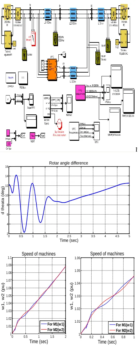
5.3 IMPACT OF UPFC (LLL-G FAULT)
The system, connected in a loop arrangement, consists basically of four buses (B1 to B4). The rating of UPFC is +/-200MVA for both series and shunt controller. The UPFC located at bus B2 is used to control the active and reactive powers at the 500-kV. consists of a phasor model of two 200-MVA, IGBT-based, converters (one converter connected in shunt and one more converter connected in series and both interconnected through a DC bus on the DC side and to the AC power system, from side to side coupling reactors and transformers). Parameters of the UPFC power components are given in the dialog box. Open the UPFC dialog box and select "Display Control parameters (series converter)". The organize parameters
of the series converter are display. prove that "Mode of operation = Power flow control". The UPFC reference active and reactive powers are set inside the blocks as a "Pref(pu)" and "Qref(pu)". primarily the Bypass breaker is closed and the resulting natural power flow at bus B2. The simulation intended for the UPFC is shown in the fig. 5.3
It
0 0.5 1 1.5 2 2.5 3 3.5 4 4.5 5
-0.2 0 0.2 0.4 0.6 0.8 1 1.2
Voltage profile for STATCOM
Time (sec)
Vm
(pu
)
0 0.5 1 1.5 2 2.5 3 3.5 4 4.5 5
-1.5 -1 -0.5 0 0.5 1 1.5
Time (sec)
Qm
(pu
)
Reactive power profile for STATCOM
0 0.5 1 1.5 2 2.5 3 3.5 4 4.5 5
2 4 6 8 10 12 14 16
Time (sec)
d
the
at
a
(de
g)
Rotar angle difference
0 0.5 1 1.5 2
1 1.01 1.02 1.03 1.04 1.05 1.06 1.07 1.08 1.09
1.1 Speed of machines
Time (sec)
w
1,
w
2
(pu
)
0 0.2 0.4 0.6 0.8 1
1 1.01 1.02 1.03 1.04 1.05 1.06
Speed of machines
Time (sec)
w
1,
w
2
(pu
)
For M1(w1) For M2(w2)
Volume: 03, Issue: 01
(JANUARY
–
FEBRUARY, 2017)
20 Fig.5.3 Waveforms for UPFC with 3-Phase (LLL-G) Fault, (a) Rotor angle difference, (b) Speed of machines, (c) Voltages profile, (d) Reactive power profile.
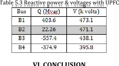
Table 5.3 Reactive power & voltages with UPFC
VI. CONCLUSION
The comparison of the SVC, STATCOM and UPFC, controller applications. The detailed models of the SVC, STATCOM, and UPFC were implemented and tested in the EMT (electro-magnetic transients). The models are relevant for transient stability analysis, and cover broader range of frequency oscillations and voltage control. The STATCOM give better performance than SVC for reactive power, voltages and loading capacity. For STATCOM reactive power compensated from 13.11 MVAR (SVC) to 15.83 MVAR (STATCOM) and voltage injected from 464.4 kv (SVC) to 469.8 kv (STATCOM) at bus 2.another relation with UPFC give better-quality performance than STATCOM for reactive power, voltages and loading capacity. For UPFC reactive power compensated from 15.83 MVAR (STATCOM) to 22.26
MVAR (UPFC) and voltage injected from 469.8 kv (STATCOM) to 471.1 (UPFC) kv at bus 2 and table no. 5.2 & 5.3.
REFERENCES
[1]. [1] M. Faridi & H. Maeiiat, M. Karimi & P. Farhadi, H. Mosleh, ‘Power System Stability Enhancement Using Static Synchronous Series Compensator (SSSC)’ 978-1-61284-840-2/11/$26.00 ©2011 IEEE.
[2]. [2] Ding Lijie, Liu Yang, Miao Yiqun ‘Comparison of
high capacity SVC and STATCOM in real power grid’
978-0-7695-4077-1/10 $26.00 © 2010 IEEE, DOI 10.1109/ICICTA.2010.586.
[3]. [3] Saurav Vishwakarma and Prof. R.K. Tripathi,
‘Transient Energy Dissipation and Damping
Improvement using STATCOM & SSSC’ 978
-1-4244-8542 0/10/$26.00 ©2010 IEEE.
[4]. [4] Xu Ting, Jiang Daozhuo, Guo Jie, Shentu Gang, Zhang
Qian, ‘Analyzing a novel controllable rectifier type SVC and de-icing device's impact on the transient stability
of power system’ 978
-1-4244-5940-71101$26.001D2010 IEEE.
[5]. [5] Morison, K., Wang, L., Kundur, P., Lin, X., Gao, W., He, C., Xue, F., Xu, J., Xu, T., and Xue, Y.: ‘Critical
requirements for successful on‐line security assessment’ Proc. IEEE PES PSC&E Conf., New York, 10
– 13 Oct 2004.
[6]. [6] H. Saadat, Power System Analysis McGraw-Hill International Editions, 1999.
[7]. [7] Ahsanul Alam, and M. A. Abido, ‘Parameter
Optimization of Shunt FACTS Controllers for Power
System Transient Stability Improvement’ 978
-1-4244-2190-9/07/$25.00 ©2007 IEEE.
[8]. [8] Huang Shao-Ping, Jin Guo-Bin, Li Ling, ‘Modeling and Simulating for Transient Stability Analysis of
Power System using Dynamic Phasor’ 978-0-7695
3887-7/09/$26.00 ©2009 IEEE.
[9]. [9] T.T. Nguyen and S. R. Wagh,’Model Predictive Control of FACTS Devices for Power System Transient
Stability’ IEEE T&D Asia 2009.
[10].[10] Telli Haman, Ahad Kazemi, ‘Improvement of Power System Transient Stability by Two Control Methods: Study and Simulation’ IEEE International
Symposium on Industrial Electronics (ISlE 2009) Seoul Olympic Parktel, Seoul, Korea July 5-8, 2009.
0 0.5 1 1.5 2 2.5 3 3.5 4 4.5 5
-0.2 0 0.2 0.4 0.6 0.8 1 1.2
Voltage profile for UPFC
Time (sec)
Vm
(pu
)
0 0.5 1 1.5 2 2.5 3 3.5 4 4.5 5 -1.5
-1 -0.5 0 0.5 1 1.5
Reactive power profile for UPFC
Time (sec)
Qm
(pu