Advanced Ceramics Progress
J o u r n a l H o m e p a g e : w w w . a c e r p . i r
Effect of Surface Roughness Morphology on Bond Strength of Thermal Sprayed
WC-10Co-4Cr Ceramic/Metal Coating
F. Naeimia, M. Tahari*b
aDepartment of Engineering, Isfahan (Khorasgan)Branch, Islamic Azad University, Isfahan, Iran bDepartment of Engineering, Esfarayen University of Technology, Esfarayen, North-Khorasan, Iran
P A P E R I N F O
Paper history:
Received 17 December 2016
Accepted in revised form 04 March 2017
Keywords:
Ceramic/metals Composite Thermal Spray Coating Bond Strength
A B S T R A C T
In this study, the effects of surface roughness and roughness morphology on the bond strength of WC-Co-Cr coatings have been investigated. Three different surface morphologies are used for this purpose. The first and second samples were sandblasted with Alumina and Silicon Carbide, respectively. The other sample was not sandblasted before spraying process. The same WC-10Co-4Cr coating was deposited on the substrates through HVOF methods. The morphology of powder, coating and substrate surface roughness have been investigated by using Scanning Electron Microscopy (SEM), and the surface roughness meter was used for measuring the surface roughness. The phase study of powder and coating was done by X-ray diffractometry. Coatings bond strength has been investigated by pull-off test. The investigated phase showed that decomposition of WC phase is very low during thermal spray process. C Porosity of the WC-10Co-4Cr coating which was calculated by using image analysis is about %1.6, whereas the hardness is 1180 HV. The pull-off test results showed that after coating process, the non-sandblasted substrate shows higher bond strength. Probably work hardening during sandblasting prevents WC particles penetration into Copper substrate. This phenomenon caused adhesion and cohesion fracture mode in Alumina and SiC, respectively, while fracture in the non-sandblasted coating occurs in epoxy.
1. INTRODUCTION1
Thermal sprayed cermet coatings have been successfully applied to produce dense coatings of high hardness and superior wear resistance [1-2]. One of the best thermal spray processes that can be used to produce these coatings is High Velocity Oxy-Fuel (HVOF). This method has higherexhaust velocities and lower flame temperature than other processes. So HVOF process can produce coatings with low porosity level (1%) and excellent wear resistance [1].
WC–Co-Cr are one of the most famous wear resistance coatings applied with HVOF method for protecting metal surface against wear. The hard WC particles in the coatings provide necessary wear resistance whereas Co matrix provides desired toughness [3-5]. Also addition of Cr to the matrix has been found to improve the toughness and corrosion resistance of these cermets [4, 6].
Tungsten carbide based coatings are frequently used for many applications such as aerospace, automotive, power
1*Corresponding Author’s Email:[email protected] (M. Tahari)
generation and steel making [2, 7].Our study presented here was about developinga thermal spray coating for continuous steel casting mold. Surface of these molds is in contact with high temperature molten and solidified steel. So, their surfaces need to have high thermal conductivity, wear resistance, corrosion resistance and high interfacial strength [2]. High thermal conductivity of copper is the most important feature which is required in continuous steel casting mold. However, copper have low hardness and wear resistance. Therefore,Surface properties can be developed by thermal spray coatings for increasing wear resistance and service life of continuous steel casting mold. These coatings need to have high hardness, suitabletoughness and excellent adhesion with copper substrate. The WC– Co-Cr is one of the best coatings in which particles provide high hardness and high wear resistance in coating, while the metal binder Co–Cr supplies the necessary coating toughness [4]. But critical point is adhesion between substrate and coating. To have an excellent tribological behavior, the coatings must have a good combination of properties that adhesion is one of them [8]. Debonding of the coating layer from the mold substrate can lead to failure of the entire system [9].
Elastic mismatch between coating/substrate, the plastic flow of the metal, and the thermal residual stresses and defects introduced into the coating/substrate system are among the reasons affecting the bond strength [9]. Preparing surface of the substrate is one of the best methods in order to ensure maximum bond strength between coating and substrate [8]. Cleaning, drying and grit blasting of surface substrate are three steps involved in surface preparation procedure prior to any thermal spray process [8].
Some of the researchers believe that during thermal spray of WC-Co coatings, temperature of substrate surface increases. It causes occurrence of partial melting of substrate so that a metallic bond could be developed between the liquid phase in the coating and the melted region of the substrate [10]. However, others believe that mechanical locks formed between surface roughness and coatings increase the bond strength [11]. Sobolove et al. showed that the surface roughness inhibitedthe flow of flattening splats on the substrate surface. So a large heat source would be available from the melted droplet to melt the substrate [12]. Droplet induces pressures in HVOF method and partial melting of substrate leads to metallic bond in interfacial zone [12].On the other hand, Staia et al. showed that residual stresses near the interface were increased with increase in substrate roughness [8].
Different methods have been used for evaluating the adhesion of thermal spray coatings and effect of substrate roughness on adhesion. Each method is related to a certain type of coating, loading condition, and application of the coating since there are no universal tests for measuring coating's adhesion [13]. Some of the most important used methods are shear tests, indentation test and tensile adhesive strength [13].Pull off test can be used for investigating adhesion and cohesion strength in the coatingssimultaneously. Aim of the present study is investigating the effects of surface roughness morphology of substrate on adhesion strength between WC–Co–Cr coatings by using a pull–off test method.
2. MATERIALS METHOD
A commercial WC–Co-Cr alloy powder (GTV) with a nominal composition of 86wt.%WC, 10wt.% Co and 4 wt.% Cr and grain size distribution of 15-45 micron was employed in this work.WC–Cr–Co coatings were deposited by HVOF spraying equipment (High Velocity Oxy-Fuel) system (Metjet-III system, Metallization, UK) on the Cu-Zr substrate. In brief, the HVOF spraying parameters are listedin Table 1.
The samples were 25.4 mm in diameter and 35 mm in height. Three samples were prepared to study the effect of substrate surface morphology on bond strength between coating and substrate. First, thesamples were washed with acetone. Thenthe samples A and B were grit blasted by alumina and silicon carbide, respectively,
but no surface treatment was performed on sample C. The grit blasting parameters are listed in Table 2.
TABLE 1. Thermal spray parameters of WC-10%Co-4%Cr
TABLE 2. Sand blasting parameters of the copper samples
Sand blasting angle (degree) Pressure (bar) sand blasting distance(mm) Mesh size Sand type Sample NO. 70 5 12 24 alumina A 70 5 12 24 SiC B ---C
Surface roughness of the substrates and coatings was measured by using a contact profilometer (Taylor Habson). Surface roughness morphology and coating microstructure were characterized by Scanning Electron Microscopy (SEM) and X-ray diffraction (XRD) in a Philips X’PERT MPD diffract meter using filtered Cu Kα radiation (λ = 0.1542 nm) was adopted for identifying the phases created in the coatings. The hardness test was performed according to ASTM-E384 method. The loading weight was 300 gr and dwell time was 10 s. Porosity of the coatings was evaluated according to the ASTM E2109 standard testing method. The fracture toughness testing was performed based on the Evans and Wilshaw method.
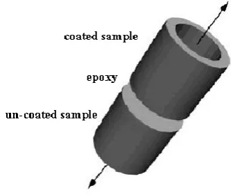
Figure 1. Schematic illustration of the samples prepared for pull-off test
Bond strength between substrates and coatings was evaluated with pull-off test (ASTM C633-79). Fig. 1 schematically shows the technical setup of this test.CK45 steel bars were used as uncoated samples and in all tests their surface roughness was the same. The samples were bonded together by using FM1000
Value Parameter 350 mm Spray distance 90 degree Spray angle 4 bar Career gas pressure
epoxy.The maximum strength of this epoxy is 55 MPa and strengthening was done at180 °C. The tensile load was applied by using a Universal Instron 8020 tension testing machine.To reduce the experimental error, the tests were repeated for three times.
3. RESULTS AND DISCUSSIONS
3.1. Characterization of the powder and coating
Fig. 2 shows the secondary electron micrograph of WC– Co-Cr powder. The morphology of this powder is almost spherical and porous. These features indicate that the agglomerated/sintered were manufactured through this method clearly. The shape and distribution size of powder were suitable for HVOFthermal spray.
Figure 2. Secondary electron micrograph of WC–10Co-4Cr powder
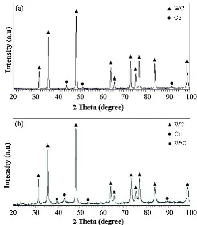
The XRD patterns of as-received powder and coating are shown in Fig. 3, A comparison between two patterns shows formation of W2C phase during thermal spray
process.Decarburization of tungsten carbide leads to formation of W2C (di-tungsten carbide) phase. The W2C
formation mechanisms during thermal spray process have also been reported by other researchers [7, 14]:
2WC + O2⇔W2C + CO2 (1)
2W2C + O2⇔2W2(CO) (2)
W2(CO)⇔2W + CO (3)
2WC⇔W2C + C (4)
Intensity of Co peak was decreased in the coating which indicates that probably due to high temperature of the HVOF process flame Co has been dissolved into the coating and maybe due to fast solidification during spray process, it exists in the form of an amorphous phase [7]. On the other hand, internal strain of metallic part of the coatings created during thermal spray decreases the peak intensity [15].
Fig. 4 shows secondary electron micrograph of the coating cross section. It can be observed that the coating have some specific micro-structure features which are common in all kinds of thermal spray processes. Due
tohigh kinetics energy of the particles in the HVOF, thermally sprayed coating has quite low porosity and it possesses a dense structure.
Porosity and other properties of the coating are presented in the Table 3, It can be observed that hardness of the coating is significantly greater than that of the copper substrate (120HV). The large hardness different between coating and substrate can be decrease bond strength between coating and substrate.
Figure 3. The XRD pattern of a) WC-10Co-4Cr powder, and b) WC-10Co-4Cr coating
Figure 4. Cross section secondary electron micrograph of WC–10Co-4Crcoating
TABLE 3. Hardness, porosity and fracture toughness of WC-10Co-4Cr
Sample Hardness %Porosity Fracture toughness
WC-10Co-4Cr 1180±40 1.6 1.8±0.2
3.2. Roughness characterization
the used sands were different. It can be observed that the roughness was almost similar for both sandblasted samples, but roughness of the sample which was not sand blasted is much less than those of the other samples.Roughness results of the coatings show that substrates roughness does not have certain effect on surface quality of the coatings.
TABLE 4. Roughness of the samples after sandblasting and coating processes
Fig. 5 shows secondary electron micrograph of surface roughness morphology of A and B samples.
In spite of the roughness values of them, the samples are same but their surface morphologies are somewhat different. It can be observed that in the sample sandblasted with alumina, curved indentations are formed on the surface, however, in the other sample the formed indentations have angular morphology.
Figure 5. Surface roughness morphology of the samples sandblasted with a) alumina, and b) silicon carbide
Differences in roughness morphology can be attributed to the different shapes of the used sands. Curved roughness was formed due to spherical morphology of alumina and angular roughness is due to irregular shape of silicon carbide. Roughness morphology can affect
strength of mechanical lock in interface between coatings and changethe adhesion strength.
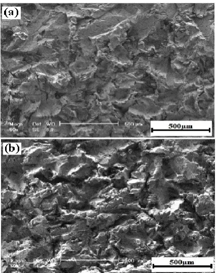
3.3. Pull–off test Results of the average failure load for all samples which were performedaccording to ASTM C-633-79 standards are almost 52-55 MPa.It can be seen that maximum strength is almost similar in all samples but these results disagree with the works performed by Staia et al. and Sobolev et al.[8,12]. They believe thatthe adhesion strength increases with increasing surface roughness.Fracture surface of the samples are showed in Fig. 6.
Their fracture surfaces have been characterized by using an optical microscopy and image analyzer software. Three modes of failure can be observed in the coatings. 1) Adhesion: this fracture mode was occurred at edge of the samples then it waspropagatedtoward the center of samples (zone I).Adhesion depends on bond strength between coating and substrate strongly. 2) Cohesion: this mode of fracture was occurred through the coatings (zone II). Some researchers believe that cohesion strength of WC thermal sprayed coatings is dependent on carbide degradation during the thermal spray process [16]. 3) Failingby separation through the epoxy (zone III).Fracture corresponding to each zone wascalculated with image analysis software and the results are presented in Table 5.
Figure 6. Fracture surface of WC-10Co-4Cr coating which were a) alumina sandblasted, b) silicon carbide sandblasted, and c) the non-sandblasted substrate
TABLE 5. Adhesion or cohesion fracture ratio in WC-10Co-4Cr coating
%Epoxy Fracture
%Cohesion Fracture
%Adhesion Fracture
Sample NO.
34
7
59
A
78
5
17
B
100
0
0
C
Ra:Coating(µm)
Ra: sandblasted (µm)
Sample NO.
5±0.2
9.4±0.6
A
5.3±0.3
10.2±0.6
B
4.9±0.1
1.9±0.1
C
It can be observed that the adhesivefailure in aluminasandblasted sample is more than other samples.Probablycurved morphology of surface roughness has decreased strength of mechanical lock in interface and cracks formed in edges were propagatedtoward the center of samples easily. But for silicon carbide sandblasted sample, angular morphology of surface roughness resulted informing strong mechanical lock between coating and substrate. High bond strength between coating and substrate prevented propagation of the cracks in the interface.
On the contrary, it was observed that the sample C has lowest roughness but it showed highest adhesion strength among three samples. Some of the researchers believe that surface treatment processes such as sandblasting result in work hardening of copper alloys [8]. Here, work hardened surface in A and B samples have probably prevented indentation of WC particles into substrate and enough strong mechanical bond could not be created between coating and substrate. However, for sample C due to soft substrate surface, WC particles with high kinetic energy were indented into substrate and high strength bond was created at interface.
4. CONCLUSION
Effect of surface roughness morphology on bond strength of WC-10Co-4Co thermal sprayed coating deposited on copper substrate has been investigated. Here, the following conclusionscan be drawn:
1. Surface roughness and morphology of roughness after sandblasting are related to sandblasting parameters and shape of the used sand. Alumina sand caused the surface morphology to become curve and silicon carbide creates angular surface morphology.
2. Bond strengths of the coatings which were Alumina and Silicon carbide sandblasted were same as the non-sandblasted samples, approximately equal to 50-52 MPa.
REFERENCES
1. Perry, J.M., Neville, A., Hodgkiess, T., "A Comparison of the Corrosion Behavior of WC-Co-Cr and WC-Co HVOF Thermally Sprayed Coatings by In Situ Atomic Force Microscopy (AFM)", Journal of Thermal Spray Technology, Vol. 11, (2002), 536-541.
2. Hamatani, H., Miyazaki, Y., "Optimization of an electron beam remelting of HVOF sprayed alloys and Carbides", Surface and
Coatings Technology, Vol. 154, (2002), 176–181.
3. Harsha, S., Dwivedi, D.K., Agrawal, A., "Influence of WC addition in Co–Cr–W–Ni–C flame sprayed coatings
onmicrostructure, microhardness and wear behavior", Surface
& Coatings Technology, Vol. 201, (2007), 5766–5775.
4. Hadad, M., Hitzek, R., Buergler, P., Rohr, L., Siegmann, S., "Wear performance of sandwich structured WC–Co–Cr thermallysprayed coatings using different intermediate layers",
Wear, Vol. 263, (2007), 691–699.
5. Celik, E., Culha, O., Uyulgan, B., Azem, N.F., Ozdemir, I., Turk, A., "Assessment of microstructural and mechanical properties of HVOFsprayed WC-based cermet coatings for a roller cylinder", Surface & Coatings Technology, Vol. 200, (2006), 4320 – 4328.
6. Maiti, A.K., Mukhopadhyay, N., Raman, R., "Effect of adding WC powder to the feedstock of WC–Co–Cr based HVOFcoating and its impact on erosion and abrasion resistance", Surface & Coatings Technology, Vol. 201, (2007), 7781–7788.
7. Maiti, A.K., Mukhopadhyay, N., Raman, R., "Improving the Wear Behavior of WC-CoCr-based HVOF Coating by Surface Grinding", Journal of Materials Engineering and
Performance, Vol. 18, (2009), 1060-1066.
8. Staia, M.H., Ramos, E., Carrasquero, A., Roman, A., Lesage, J., Chicot, D., Mesmacque, G., "Effect of substrate roughness induced by grit blasting upon adhesion of WC-17% Co thermal sprayed coatings", Thin Solid Films, Vol. 377, (2000), 657-664.
9. Lv, H., Nie, P., Yan, Y., Wang, J., Sun, B., "Characterization and adhesion strength studyof detonation-sprayed MoB–CoCr alloy coatingson 2Cr13 stainless steel substrate", Journal of
Coating Technology, Vol. 7, (2010), 801–807.
10. Guilemany, J.M., Nutting, J., Dong, Z., "Coating – substrate bonding after HVOF thermally spraying WC–Co onto a Ti– 6%Al–4%V alloy", Journal of Materials Science Letters, Vol. 16, (1997), 1043–1044.
11. Du, H., Hua, W., Liu, J., Gong, J., Sun, C., Wen, L., "Influence of process variables on the qualities ofdetonation gun sprayed WC–Co coatings", Materials Science and Engineering, Vol. 408, (2005), 202–210.
12. Sobolev, V.V., Guilemany, J.M., Calero, J.A., "Development of Coating Structure and AdhesionDuring High Velocity Oxygen-Fuel Sprayingof WC-Co Powder on a Copper Substrate",
Journal of Thermal Spray Technology, Vol. 9, (2000),
100-106.
13. Hadad, M., Hockauf, M., Meyer, L.W., Marot, G., Lesage, J., Hitzek, R., Siegmann, S., "Adhesion evaluation of multilayered based WC–Co–Cr thermally sprayed coatings", Surface & Coatings Technology, Vol. 202, (2008), 4399–4405.
14. Zhan, Q., Yu, L., Ye, F., Xue, Q., Li, H., "Quantitative evaluation of the decarburization and microstructure evolution of WC–Co during plasma spraying", Surface & Coatings
Technology, Vol. 206, (2012), 4068–4074.
15. Tahari, M., Shamanian, M., Salehi, M., "Microstructural and morphological evaluation of MCrAlY/YSZ composite produced by mechanical alloying method", Journal of Alloys and
Compounds, Vol. 525, (2012), 44– 52.