ISSN: 2334-2986 (Print), 2334-2994 (Online) Copyright © The Author(s). 2014. All Rights Reserved. Published by American Research Institute for Policy Development
Quasi Elliptic Bandpass Filter with Defected Ground Structure for Improved Performance
Prof. Dr Mazlina Esa1, N. N. N. Abd Malik2 and M. K. H. Ismail3
Abstract
Filters are widely used in the telecommunication industry in recent years. They selectively sort signals and pass through a desired range of signals while suppressing or removing others. This project presents the design of a quasi-elliptic bandpass filter (QE) that operates at 2.4 GHz employing Defected Ground Structure (DGS) slot. The objective of this project is to enhance the performance of a bandpass filter in terms of better return loss and increased bandwidth by employing DGS element in the ground plane. The chosen filter topology is based on a square open loop resonator. DGS elements of rectangular geometries have been chosen for the project. Two sets of QE filters have been designed and investigated. The first set is without DGS, while the second set is with variations of rectangular DGS slot elements. The filters are named QE and QE_R filter sets. The effects of introducing DGS slots into the filter ground plane have been successfully investigated. It is observed that the QE_R filter exhibits excellent low return loss at 2.4 GHz, and increased operating bandwidth, compared to the QE filter. The optimum configuration is chosen to be the QE_2R filter. It is observed that the QE_2R filter exhibits excellent simulated low return loss of -28.07 dB at 2.4 GHz, and the bandwidth of the filter reached to 98.39 MHz which is 19.39 MHz wider than QE filter. Its stopband responses are quite similar, ie approximately -30 dB, within the observed lower and higher bands.
Keywords: quasi-elliptic bandpass filter; defected ground structure; microstrip; loop resonator; and enhanced performance
1 UTM-MIMOS COE for Telecommunication Technology, Faculty of Electrical Engineering,
Universiti Teknologi Malaysia, 81310 UTM Johor Bahru, Johor, Malaysia. Phone: +6075535262, E-mail: [email protected]
2 Department of Communication Engineering, Faculty of Electrical Engineering, Universiti Teknologi
1. Introduction
Filters are important components being widely used in the telecommunication industry. A filter selectively sorts signals and passes through a desired range of signals while blocking or suppressing others. This article presents the design of a quasi-elliptic bandpass filter, named QE filter. It operates at 2.4 GHz, and is integrated with Defected Ground Structure (DGS). The design aims for enhanced performance in terms of better return loss and increased operating bandwidth. The chosen filter topology is based on a square open loop resonator. DGS elements of rectangular geometries are integrated in the ground plane. Two sets of QE filters have been successfully designed and simulated. The first set is without DGS, while the second set is with variations of rectangular DGS slot elements. The filters are named QE and QE_R filter sets. It is observed that the QE_R filter exhibits excellent low return loss at 2.4 GHz, and increased operating bandwidth, compared to the QE filter.
2. Quasi Elliptic Filter and DGS Structures
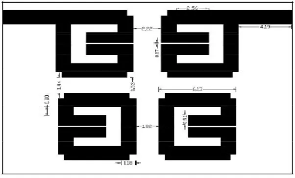
A QE filter which consists of four square resonators shown in Figure 1 has been successfully simulated (Mohd Akram 2009). The main advantage of the open square resonator is its ability to provide both positive and negative coupling coefficients, but alleviate the limitation on the strength of the coupling coefficient which can be implemented.
One recently introduced method to improve the filter characteristics is to have defected ground plane. Various slot geometries have been reported in the literature for the purpose of reducing harmonics, producing frequency pass or stop-bands, and enhancing coupling effects (A. Abdel-Rahman 2006). A DGS cell behaves as complementary to the main filter and independently in executing the filter, due to its natural resonant characteristic.
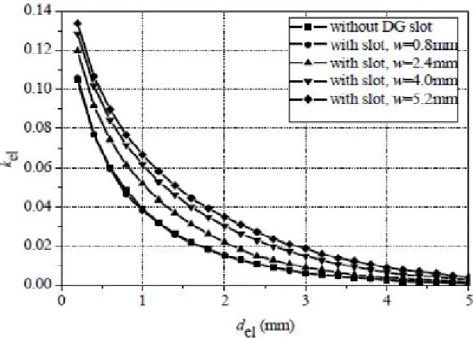
A periodic structure or slot geometry present on the ground plane can disturb the field distribution of the guided electromagnetic wave and create an electromagnetic bandgap (EBG) effect within certain frequency ranges. The effect is useful for suppressing undesired harmonics and preventing undesired signals in the components, which is the primary function of filters. The DGS structure can be realised by etching off its geometry from the conducting ground plane. Such slot in the ground plane can enhance the electric coupling, or the electric part of a mixed coupling between two adjacent resonators. The behavior can be seen in Figures 2 and 3.
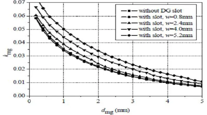
Fig. 3 shows the dependence of the electric coupling coefficient on the gap between resonators, for several width values of the ground slot. The presence of slot enhances the electric coupling coefficient. The magnetic coupling coefficient is slightly larger, compared to the classical microstrip structure.
Figure 3: Magnetic Coupling Coefficient vs. Coupling Gap (N. Militaru 2007)
An etched defect in ground plane disturbs the shield current distribution that is present. The disturbance can change the characteristics of a transmission line such as line capacitance and inductance.
3. Design of Quasi-Elliptic Filter
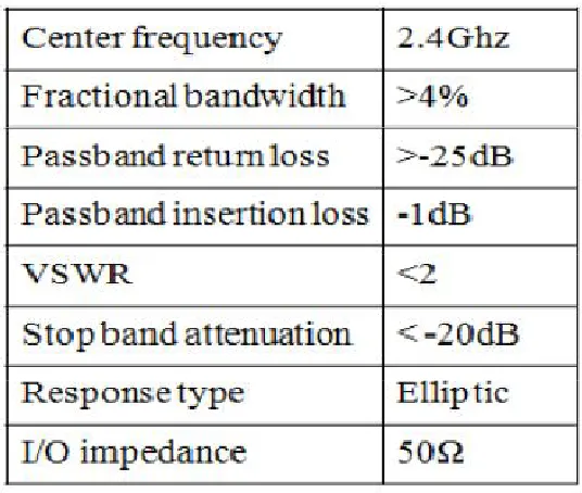
Table 1: Quasi Elliptic Filter Specification
Table 2: RT/Duroid 6010 Material Properties
Figure 4: Square Resonator
There are several DGS shapes that have been reported in the literature such as alphabetical, hexagonal, circular and dump-bell shapes. For the design, rectangular geometry has been chosen (M. Azfar A. Aziz 2011). Both the QE filters, with and without DGS element are simulated and analysed. Further investigations were carried out with varying DGS sizes. The performances are then compared.
Figure 5 shows the proposed geometry of DGS element.
4. Simulation Results and Analyses
Simulations were performed using electromagnetic simulation software. Optimisations were carried out for fine-tuning in order to obtain an optimum configuration of the filter with integrated DGS elements. Two sets of QE filters are designed and simulated. The first set is without
DGS, while the second set is with variations of rectangular DGS slot elements. The filters are as follows:
i. Quasi elliptic Bandpass Filter without DGS Element, QE
ii. QE filter with first rectangular DGS of electric coupling, QE_R1 iii. QE filter with second rectangular DGS of magnetic coupling, QE_R2 iv. QE filter with two rectangular DGS Slots, QE_2R
4.1 QE Filter
The simulated results of the QE filter are shown in Figure 6. It can be observed that the filter showed elliptic response. It has central frequency of 2.4 GHz, and operating bandwidth of 79.15 MHz. Slight ripple of insertion loss is observed above the -3 dB level. Return loss is between -5 dB and -23.5dB within the passband region, indicating good impedance match at the input. The region occurs slightly lower than –3 dB level. Two close transmission zeros are observed at the lower and higher bands. Within the observed window, the stopband response is below -30 dB, indicating excellent stopband. The transition bands are almost symmetrical.
4.2 QE_R1 Filter
Figure 6 shows the geometrical layout and dimensions of the R1 DGS slot. Simulated responses are shown in Figure 7. It can be observed that good simulated return loss of better than -15 dB is obtained over the passband region, which is better than QE filter. Excellent return loss of -31.23 is obtained at 2.42 GHz. The filter operates from 2.37 GHz to 2.45 GHz, with a bandwidth of 85.71 MHz Two close transmission zeros are observed at the lower and higher band. Within the observed window, the stopband response is below -20 dB, indicating good stopband. The transition bands are less symmetrical compared to QE filter.
Figure 6: Geometrical Layout and Dimension of R1 DGS Slot
4.3 QE_R2 Filter
The geometrical layout and dimensions of the R2 DGS slot are shown in Figure 8. Figure 9 shows the simulated responses. It can be seen that sufficient passband return loss below -5 dB is observed. It records return loss of -14.87 dB at 2.4 GHz. The -3 dB bandwidth of the filter is 105.49 MHz, which is from 2.36 GHz to 2.47 GHz. The value is 25 MHz broader than QE_R1 filter. Stopband responses are below –30 dB at the lower and higher bands. Although better than that of QE_R1 filter, its return loss within the passband region is worse. This could be due to the effect of weak magnetic coupling compared to the electric coupling, contributed by the DGS slot.
Figure 8: Geometrical Layout and Dimensions of R2 DGS Slot
4.4 QE_2R Filter
In order to improve the stopband performance of the QE filter using one DGS slot, the filter is modified by having two DGS units. For QE_R1 filter, optimum R1 size is 10 mm² while for QE_R2 filter, optimum size is 12 mm². Figure 10 shows the geometrical layout and dimensions of the two proposed DGS slots.
Simulated responses are shown in Figure 11. It can be seen that the QE_2R filter is operating well at a centre frequency of 2.4 GHz, as desired with excellent good return loss of -28.07 dB and narrower operating bandwidth of 98.39 MHz or 4.5 %. The corresponding VSWR is 1.15. The value is approximately 6 MHz narrower than QE_R1 filter, but 18.39 MHz broader than QE_R2 filter. Stopband responses are similar ie –30 dB within the observed lower and higher bands. Its return loss within the passband region is better than -12 dB, which is sufficiently obtained. This could be due to the combination effect of the weaker magnetic coupling and stronger electric coupling, contributed by the DGS slots.
Figure 11: Simulated Responses of QE_2R Filter
5. Overall Discussion
The performance parameters of the four bandpass filter are tabulated and compared in Table 3. All bandpass filters operate well at similar operating frequencies, close to the desired 2.4 GHz, with excellent return losses of below -10 dB. The proposed QE_2R bandpass filter structure, employing the two DGS slots, has a wider fractional bandwidth of approximately 4.5 % at the centre frequency of 2.4 GHz compared to 3.3% for the conventional QE filter which is 19.39 MHz wider. This is because of the effect from the DGS structures that give tight couplings between adjacent resonators.
Table 3: Summary of Simulated Performance
6. Conclusion
References
David M. Pozar (2005). Microwave Engineering, New York: Wiley
Jia-Sheng Hong, M. J. Lancaster (2001). Microstrip Filters for RF/Microwave Applications. New York: Wiley
Nima Molaei Garjani, Nader Komjani (2009). Quasi-Elliptic SIR Bandpass Filter with Defected Ground Structure. Proc. of Asia Pacific Microwave Conference. IEEE Computer Society.
A. Abdel-Rahman, A. R. Ali, S. Amari, A. S. Omar (2006). Compact Bandpass Filter Using Defected Ground Structure (DGS) Coupled Resonator. Proc. Of Microwave Symposium Digest. IEEE.
Dal Ahn, Jun-Seok Park, Chul-Soo Kim, Juno Kim (2001). Design of the Low-Pass Filter Using the Novel
Microstrip Defected Ground Structure. IEEE Transactions on Microwave Theory and Technique, Vol. 49. No. 1.
N. Militaru, M. G. Banciu, G. Lojewski (2007). Novel microwave bandpass filters using defected-ground structures. Journal of Optoelectronics and Advanced Material. Vol. 9, No. 4, April, pp. 1060 – 1064
E. Yablonovitch (1993). Photonic band-gap structures. Vol. 10, No. 2, February. J. Opt. Soc. Am. B.
L. H. Weng, Y. C. Guo, X. W. Shi, and X. Q. Chen (2008). An Overview on Defected Ground Structure. Progress In Electromagnetics Research B. Vol. 7, 173–189. N. Militaru, M. G. Banciua, G. Lojewski (2007). Novel microwave bandpass filters using
defected-ground
structures. Journal Of Optoelectronics and Advanced Materials. Vol. 9, No. 4, April. pp. 1060 – 1064
A. Abdel-Rahman, A. K. Verma, A. Boutejdar, and A. S. Omae (2004). Compact Stub Type Microstrip
Bandpass Filter using Defected Ground Plane. IEEE Microwave and Wireless Components Letters. Vol. 14, No. 4, April.
Renbin Wu and Smain Amari (2004). Two-Layer Elliptic Filter with Enhanced Bandwidth. Department of Electrical and Computer Engineering, Royal Military College of Canada.
Mohd Akram Zainal Abidin (2009). Design A Microstrip Quasi Elliptic Bandpass Filter For Microwave
Application Operating at 2.4 GHz. Unpublished Dissertation. Faculty of Electrical Engineering, Universiti Teknologi Malaysia.
Mohd Azfar A. Aziz (2011). Design of Quasi Elliptic Bandpass Filter with Defected Ground Structure for