Available Online at www.ijpret.com 243
INTERNATIONAL JOURNAL OF PURE AND
APPLIED RESEARCH IN ENGINEERING AND
TECHNOLOGY
A PATH FOR HORIZING YOUR INNOVATIVE WORK
DESIGN AND ANALYSIS OF TWO ELEMENTMICROSTRIP PATCHANTENNAEARRAY
FOR GPS AND WI-FI
A.M. SORTY, A. G. DEOKAR, S. R. DARADE, D. P. TULASKAR
Department of Electronics and Telecommunication Engg.,Shri Sant Gajanan Maharaj College of Engg.,Shegaon-444203.
Accepted Date: 15/03/2016; Published Date: 01/05/2016
\
Abstract: Microstrip Patch Antennas (MPA) are getting more popular due to their variety of
advantages such as low cost, light weight, low profile. This has given patch antenna an innovative significance in wireless communication. Also, these antennas are competent with microwave circuits and thus used for WALN applications, navigation systems and much more. But, single MPA has some disadvantages such as narrow bandwidth, low gain, low directivity and are less efficient. This can be overcome by accomplishing patches in array. As the number of patches have increased the performance of the antenna increases. The proposed antenna array is designed for Wi-Fi and GPS and performance parameters of the array is observed in ADS software.
Keywords: Microstrip patch antenna, Return loss, Array, Wireless communication, Radiation
pattern, Substrate.
Corresponding Author: A. M. SORTY Access Online On:
www.ijpret.com
How to Cite This Article:
Available Online at www.ijpret.com 244
INTRODUCTION
Available Online at www.ijpret.com 245
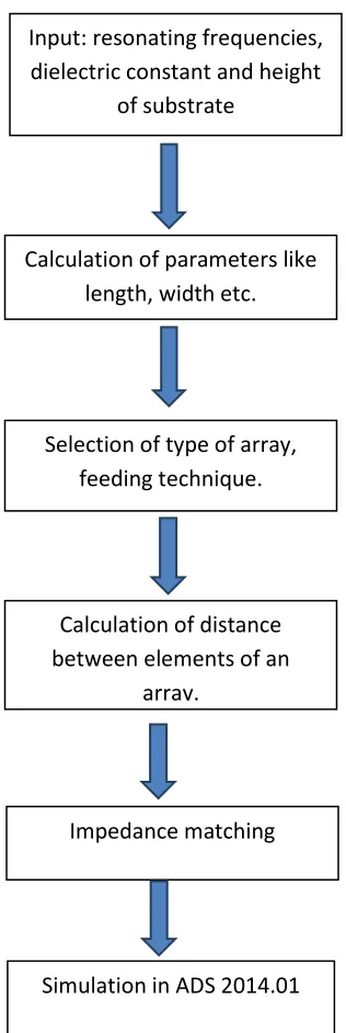
Figure 1: Flow of antenna array design
II. literature Review- The history of antenna dates back to James Clerk Maxwell who unified the theory of electricity and magnetism, and represented the relations with the set of equations best known as Maxwell’s equations in 1873 [2]. In 1886, Professor Heinrich Rudolf Hertz demonstrated the first electromagnetic system[2]. In 1901, Guglielmo Marconi was able to send signals over large distances. He performed in 1901 the first transatlantic transmission
Input: resonating frequencies, dielectric constant and height
of substrate
Calculation of parameters like length, width etc.
Selection of type of array, feeding technique.
Calculation of distance between elements of an
array.
Impedance matching
Available Online at www.ijpret.com 246 Poldhu in Cornwall, England to St. Johns Newfound land [5]. The beginning of 20th century until World War 2 mark the boom in wire antenna technology and wireless antenna technology as a whole. Radio links are realized upto UHF and over thousands of kilometres [2][5].
III. Material and Method of Microstrip Patch Antenna Array-
Microstrip antennas are very versatile and are used, among other things, to synthesize a required pattern that cannot be achieved with a single element. In addition, they are used to increase the directivity, and perform various other functions which would be difficult with any one single element. The elements can be fed by a single line or by multiple lines in a feed network arrangement, so in this paper we used an array to develop the performance of this antenna [1][2][7]. One of the essential parameters for the design of a rectangular microstrip patch antenna is the Frequency of operation ( fr ). The resonant frequency of the antenna must be selected appropriately [7]. Hence the antenna designed must be able to operate in the specified frequency range. The resonant frequency selected for our design are 2.4 GHzfor Wi-Fi and 1.57GHz for GPS. The proposed antenna is designed for three different frequencies. Selection of substrate is also important terminology in antenna design. The use of high permittivity substrate can miniaturize microstrip antenna size. Thick substrate with lower range offers better efficiency and wide bandwidth but it requires larger element size[8]. Substrate used in proposed antenna array is FR-4 with dielectric constant 4.4 and height of substrate is 1.6mm.
Where,
Available Online at www.ijpret.com 247 V. Feeding Techniques- There are mainly three types of feeding network in antenna design. These are
1. Series Feed Network 2. Corporate Feed Network
3. Corporate Series Feed Network
IV. Design Formulae of Microstrip Patch Antenna Array- Width of Patch-
Length of Patch-
where,
For the proposed antenna array the corporate feed network is used, as corporate feed arrays are general and versatile. This feeding technique has more ability to control the feed of each element. It is also ideal for scanning the phased arrays, multi-beam arrays [8]. The corporate feed network is used to provide power splits of 2n (i.e. n= 2; 4; 8; 16; etc.). This can be achieved by using quarter wavelength transformers.
VI. Design Specifications-
a. For GPS:
`
Table 1: Specification for GPS
`Operating Frequency 1.57 GHz
Substrate FR4
Height 1.6 mm
Patch Length 45.28 mm
Patch Width 58.14 mm
Available Online at www.ijpret.com 248
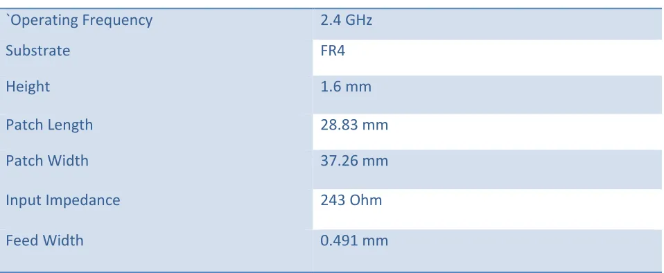
Table 2: Specifications for Wi-Fi
The all above specifications are of standard values of the signals. The calculations are done manually as well as verified on the software simulations and theoretical and simulated results are matched.
The simulation of the antenna array is perfectly performed in the Advanced Design System (ADS 2014.01). The performance of the proposed antenna is good for the signals of the frequencies below 10 GHz, as microstrip patch antennas are good resonator for frequencies below 10 GHz. The hardware of the proposed antenna is to be fabricated in the laboratory.
VII. Result and Conclusion-
The figure shows the layout of two element array for proposed design which is for Wi-fi signal and GPS signal.
Feed Width 37.26 M
`Operating Frequency 2.4 GHz
Substrate FR4
Height 1.6 mm
Patch Length 28.83 mm
Patch Width 37.26 mm
Input Impedance 243 Ohm
Available Online at www.ijpret.com 249
Figure 2 : Layout of Array Design
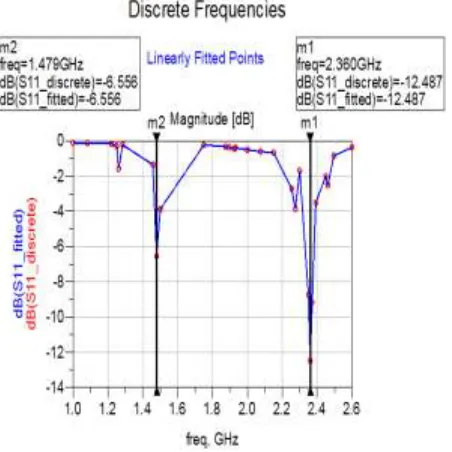
The following plot shows the return loss for the proposed antenna array. Reflection Coefficient must be above the -10dB for maximum power to be radiated. The plot shows the quite good result for two elements of the array.
Figure 3: Return Loss plot
Available Online at www.ijpret.com 250
Table 3: Results for GPS
Operating Frequency 1.5GHz
Input Power 0.00147watts
Radiated Power 0.00112watts
Directivity 6.35dB
Gain 5.15dB
Radiation Efficiency 75.93%
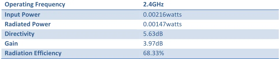
For Wi-fi signal which is operated on 2.4GHz.
Table 1: Results for Wi-Fi
Operating Frequency 2.4GHz
Input Power 0.00216watts
Radiated Power 0.00147watts
Directivity 5.63dB
Gain 3.97dB
Radiation Efficiency 68.33%
Thus, by designing array of an antenna the directivity, gain and bandwidth of an antenna can be increased to great extent. The return loss of array is found to be very good for both the frequencies. The gain for GPS antenna is good than that of the Wi-Fi, the impedance is matched to a great extent. The radiation efficiency of both the antennas found is good. The array is to be increased for 4 element i.e. for satellite TV signals, for that work is still going on.
REFRENCES:
1. Kin-lu-Wang,”Compact and Broadband microstrip antennas”, John wiely and sons,Inc.2002
2. Balanis, Constantine, 1997” Antenna Theory- Analysis and Design”, John wiely and sons ltd.
3. Ahmed Fatthi Alsagar, PhD Thesis, “Design and Analysis of Micro strip Patch Antenna
Arrays”.
4. Jaswindar Kaur and Rajesh Khanna,”Coaxial fed Microstrip patch Antenna for 5.2GHz WLAN
Application” ,Univerasal Journal of Electric and Electronic Engineering 1(3):94-98,2013.
5. John D. Kraus, “Antennas”, McGraw-Hill Book Company, ISBN 0-07-100482-3, 1988
6. Arun K. Saurabh, Sunil Kumar, D.K.Shrivastava,”Design and Bandwidth Enhancement of
Available Online at www.ijpret.com 251 ”,International Journal of Advanced.Research in Computer and Communication Engineering, vol 2,issue 12,December 2013.
7. Alak Majumdar,”Rectangular Microstrip Patch Antenna using Coaxial probe Feeding
Technique to operate in S-band”,Intenational Journal of
8. Md Tanvir Isthaque-ul Huque, Md Kamal Hosain,”Design and Analysis of Microstrip Array
Antennas with optimum parameters of X-band Application”,International Journal of Advanced Computer scence and Applications, vol-2,no.04, 2011.
9. Amel Boufrioua and Abdelmadjid Bengalia,” Effects of the resistive patch and the uniaxial