Comparative Analysis of DWT Based OFDM System with
DCT Based OFDM System for Image Transmission and
Compression
Garima Govil
*and Priyanka Agrawal
Date of publication (dd/mm/yyyy): 11/02/2017
Abstract – Continued growth in demand for high speed communication has evolved, with the development of orthogonal frequency division multiplexing (OFDM) for various multicarrier modulation Techniques. In OFDM a large number of closely spaced orthogonal carriers are used to carry data. Discrete wavelet transform (DWT) and discrete cosine transform (DCT) is widely regarded as an effective way to replace the traditional FFT based OFDM system due to its better time frequency positioning, improved bit rate, interference & bandwidth efficiency.
In the study presented, I am Comparing a DWT based OFDM System with DCT based OFDM system for image transmission and compression. Performance is based on AWGN Channel. I am using MATLAB 2013 R simulation software as comparing tool between both systems.
Keywords – AWGN, BER, DCT, DWT, FFT, IFFT, OFDM, MSE, PSNR.
I.
I
NTRODUCTIONThe thriving demand for multimedia services and the growth of Internet-related content leads to more and more attention to high-speed communications [1].
In OFDM, high-speed data stream is divided in to narrow band data flow. OFDM symbol comprises a QAM or PSK modulation. By adding a cyclic prefix to each symbol, the symbol duration is made even longer. As long as the cyclic prefix is more than the channel delay spread, OFDM offers inter-symbol interference (ISI) free transmission. Another key advantage of OFDM is that it significantly reduces equalization complexity by balancing equalization in the frequency domain. OFDM, implemented with IFFT at the transmitter and FFT at the receiver, converts the wideband signal, affected by frequency selective fading, into N narrowband flat fading signals thus the equalization can be executed in the frequency domain by a scalar division carrier-wise with the subcarrier related channel coefficients.
II.
DCT
B
ASEDOFDM
S
YSTEMThe DCT is a Fourier-related transform. It uses only real numbers. The simplest way to formulize DCT to transform N real numbers xo,…..,xN-1 into N real numbers X0,...,
XN-1 is
1 , ,... 1 , ) ( ) 2 1 ( cos
1
0
N k
k n N x
X N
n n k
(1)
The sequences normally used in any kind of transform from one domain to the other are referred to as the basis sequences, and these are complex recurring sequences in case of Discrete Fourier Transform. Thus, it is necessary to find out if there exist some real valued basis sequences that would result in a real valued transform sequence.
Discrete Cosine Transform (DCT) expresses a sequence of definite data points in terms of a sum of cosine functions fluctuating at different frequencies.
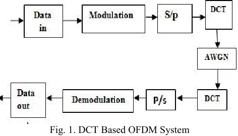
Fig. 1. DCT Based OFDM System
In DCT based OFDM System Image is modulated by suitable modulation scheme.
Fig. 2. DCT Coding Procedure
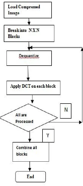
As shown in Fig 2. in DCT Coding we first break the image in N*N blocks & apply DCT algorithm on each blocks, then rounded off the coefficients. Fig. 3 shows the DCT decoding procedure at receiver side, Firstly load compressed image then break it into N*N blocks. Thereafter each block will be de-quantized and then we apply inverse DCT transform on each block and at last combined them to get final image.
III.
DWT B
ASEDOFDM
S
YSTEMThe wavelet transform gives us multi-resolution picture of a signal. At high frequencies it provides a good time resolution and for low frequencies it provides better frequency resolution, this is because the transform is enumerated using a mother wavelet and different basis functions which are generated from the mother wavelet through scaling and translation operations. Hence it having variable window size which is wide at low frequencies and narrow at high frequencies, thus providing optimal resolution at all frequencies. Wavelets are small waveforms with a set oscillatory structure that is non-zero for a limited period of time (or space) with additional mathematical properties [9].
Fig. 3. DCT Decoding Procedure
Fig. 4. Discrete Wavelet Transform Block Diagram
The bits are first interleaved with help of convolution encoder and interleave and then the data is processed using modulator to map the input data into symbols based on the modulation technique used. The DWT-OFDM symbol (𝑡) can be represented as equation (2):
𝑠 (𝑡) =
j k
𝑤𝑗,𝑘(𝑡 )𝜓𝑗,𝑘 (𝑡 )+ (𝑡 )+k
𝑎𝐽,𝑘𝜑𝐽,𝑘 (2)The orthogonality of these carriers relies on time location (k) and scale index (j).orthogonality between the subcarriers gets disordered because the demodulator correlation interval for one path will overlie with the symbol boundary of different path.[4][5]. This symbol is clearly the weighted sum of wavelet and scale carriers which is similar to the Inverse Wavelet Transform (IDWT). In DWT-OFDM, the input data is processed same as in FFT-OFDM but the advantage in this case is that the cyclic prefix is not required because of the overlapping nature of wavelet properties. The data is processed in the IDWT block, whose output can be given as equation (3).
𝑑 (𝑘) =
0 0
m n
𝐷
𝑚𝑛2
𝑚/2(2𝑘
𝑚−𝑛)
(3)
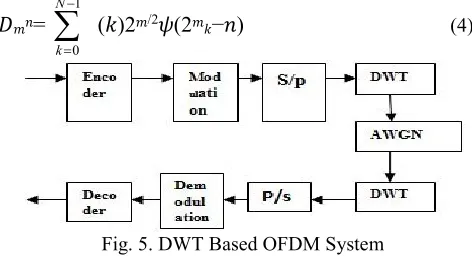
where 𝑘 is the number of subcarriers (0 ≤ 𝑘 ≤ 𝑁 – 1), 𝐷𝑚𝑛 are the wavelet coefficients which represents the signal in scale and position on time-axis and 𝜓(𝑡) is the wavelet function with compressed factor 𝑚 times and shifted 𝑛 times for each subcarrier .At the receiver side, the process is reversed. The output of discrete wavelet transform (DWT) is represented by equation (4)
𝐷
𝑚𝑛=
1
0
N
k
(𝑘)2
𝑚/2𝜓(2
𝑚𝑘−𝑛)
(4)Fig. 5. DWT Based OFDM System
For fast implementation algorithms, DCT can provide fewer computational steps than FFT based OFDM [2].
IV. S
IMULATION&
R
ESULTSHere we are using MATLAB 2013 R for our simulation work. We are comparing DCT based OFDM system with DWT based OFDM system on different performance asset like PSNR(Peak Signal to Noise Ratio), and BER (Bit Error Rate) at different SNR( Signal to Noise Ratio) .
4.1 Implementation of DCT Based OFDM System for
Image Transmission and Image Compression:
Fig. 6. Example of source image for transmission
Fig. 7. Example of Received image after transmission
Figure 6 shows the source image acting as input for transmission in DCT-OFDM system whereas figure 7 shows the received image after transmission using DCT-OFDM system. The image acting as a input can be selected by user by giving the extension name after the image present in current working directory in MATLAB.
(a) Performance Analysis of DCT Image Transmission
Performance analysis of the proposed system is done on base of following two parameters-
Plot of Peak Signal to Noise Ratio (PSNR). Plot of Bit Error Rate (BER).
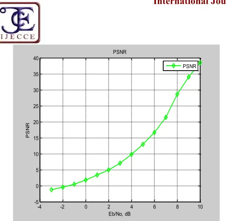
PSNR Output- The plot of peak signal to noise ratio for the image is given as follows-
Image – Lena.jpg (Standard Image)
-4 -2 0 2 4 6 8 10 -5
0 5 10 15 20 25 30 35 40
Eb/No, dB
P
S
N
R
PSNR
PSNR
Fig. 8. Plot of Peak Signal to Noise Ratio (PSNR) in DCT-OFDM
BER Output - The plot of bit error rate(BER) for the image is given as follows
-Channel- AWGN (White Gaussian Noise)
-2 0 2 4 6 8 10
10-5 10-4 10-3 10-2 10-1
Eb/No, dB
B
it
E
rr
or
R
at
e
Gaussian Noise BER curve for DCT source coding with OFDM
theory simulation
Fig. 9. Plot of bit error rate (BER) in DCT-OFDM
4.2 Implementation of DWT Based OFDM System for
Image Transmission and Image Compression:
Fig. 10. Source Image For Transmission In DWT
Fig. 11. Received image after transmission in DWT
(a) Performance Analysis of DWT Image Transmission
Performance analysis of the proposed system is done on base of following two parameters-
Plot of Peak Signal to Noise Ratio (PSNR). Plot of Bit Error Rate (BER).
PSNR Output - The plot of peak signal to noise ratio for the image is given as follows-
Channel- AWGN (White Gaussian Noise)
-4 -2 0 2 4 6 8 10
30.5 31 31.5 32 32.5 33
Eb/No, dB
P
S
N
R
PSNR
PSNR
Fig. 12. Plot of Peak Signal to Noise Ratio (PSNR) in DWT-OFDM
BER Output- The plot of bit error rate(BER) for the image is given as follows-
-2 0 2 4 6 8 10
10-5 10-4 10-3 10-2 10-1
Eb/No, dB
B
it
E
rro
r R
at
e
Gaussian Noise BER curve for Wavelet source coding with OFDM
theory simulation
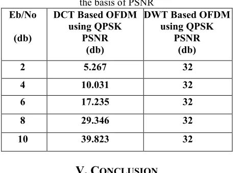
4.3 Comparative Analysis:
Table 1. Comparative analysis between DCT & DWT on the basis of PSNR
Eb/No
(db)
DCT Based OFDM using QPSK
PSNR (db)
DWT Based OFDM using QPSK
PSNR (db)
2 5.267 32
4 10.031 32
6 17.235 32
8 29.346 32
10 39.823 32
V. C
ONCLUSIONHere We are comparing two systems for Image transmission & Compression having different transform methods, First is Discrete Cosine Transform and second one is Discrete Wavelet Transform on two performance assets i.e. Peak Signal to Noise Ratio and Bit Error Rate. After a comparative analysis, I concluded that Discrete Wavelet transform gives steady output at various signal to noise ratio, That means in the noisy environment it is better to adopt DWT , But when signal power strengthen than noise power one can switch to DCT for getting more PSNR.
VI. F
UTURES
COPEFinally it is important to underline that wavelet theory is still developing. There are many possibilities for future work in this area, and are summarized as follows:
Diversity Scheme- Selection of mother wavelet can be a matter of research in future.
Channel Estimation: Channel estimation and equalization techniques can be implemented for better result.
PAPR :In OFDM PAPR is a serious problem the efficiency of proposed system should be analyzed with respect to PAPR and it should be validated for better output in terms of BER and PAPR (CCDF).
R
EFERENCES[1] Anshul Soni, S.J. Basha, Ashok Chandra Tiwari ,”Comparative Analysis of OFDM under FFT and DWT Based Image Transmission “, International Journal of Innovative Research in Computer and Communication Engineering , Vol. 1, Issue 2, April 2013 .
[2] Achala Deshmukh, Shrikant Bodhe,” Comparison of DCT and Wavelet Based OFDM System Working in 60 GHz Band”, International Journal of Advancements in Technology, Vol. 3 No.2, April 2012.
[3] S. A. Fechtel, “A novel approach to modelling and efficient simulation of frequency selective fading radio channels,” IEEE Journal on Selected Areas of Communication, vol. 11, pp. 422–431, 1993.
[4] L. J. Cimini Jr., “Analysis and simulation of a digital mobile channel using orthogonal frequency division multiplexing,” IEEE Transactions on Communication, vol. COM-33, no. 7, pp. 665–675, 1985.
[5] M. I. Doroslovacki and H. H. Fan, “Wavelet based Linear System Modelling and Adaptive Filtering”, IEEE Transactions on Signal Processing, vol. 44, no. 5, pp. 1156-1167, 1996.
[6] R. Kumar, S. Malarvizhi, S. Jayashri, “Time-domain equalization technique for intercarrier interference suppression in OFDM systems”, Information Technology Journal, vol. 7, pp. 149-154, 2008.
[7] G. W. Wornell, A. V. Oppenheim. “Wavelet-based representations for a class of self-similar signals with application to fractal modulation”, IEEE Transactions on Information Theory, 38(2):785.800, 1992.
[8]
Karanpreet Kaur, Ankush Kansal, “Performance Analysis of Convolutional Interleaved DWT Based OFDM System ”, International Journal of Advanced Research in Computer & Communication Engineering, Vol.3, Issue 5, May 2014.ISSN: 2278-1021 (online), Page No.:6601-6604.
[9] Rohit Bodhe, Shirish Joshi ,Satish Narkhede, ”Performance Comparison of FFT and DWT basedOFDM and Selection of Mother Wavelet forOFDM”. International Journal of Computer Science and Information Technologies, Vol. 3 (3), 2012, Page No.:-3993-3997.ISSN: 0975-9646.