Software,
Silicon Chips and
Structured Lighting
for Image Processing
A thesis presented for the degree
of
Doctor of Philosophy
in the
Department of Electrical and
Electronic Engineering
at the
University of Canterbury
by
M.J. Naylor B.E.(Hons)
( </ , q I
A
stract
Cont nts
Abstract Contents List of Figures List of Tables Acknowledgements
1 Introduction
2 Advanced Software Written for Interactive Image Processing Sys-tems
2.1 Introduction.
2.2 An Introduction to HIPS and iRMX86
..
II
VB
.
IX
X
1
8
8
9
2.3 The LET Command - An Equation Parser for the Serendip Command Language on HIPS . . . .. 11
2.3.1 Introduction... 2.3.2 The Specification for the LET Command. 2.3.3 The Development of the LET Command 2.3.4 The New LET Command . . . .
2.3.5 The Definition of a Syntax for LET Expressions 2.3.6 The LET Program
2.3.7 Discussion... ..
2.4 CLEAN - A Rou tine to Sort iRMX86 Directories
2.5 DIRTREE - A Program to List iRMX86 Directory Trees
11
12
14
15 18
20
2.6
A HIPS Utility for Transferring Files Over a Serial Link.27
2.6.1
Introduction . . .27
2.6.2
A Description of KERMIT .28
2.6.3
How the HIPS Version of KERMIT is Used28
2.6.4
The Modules that Constitute HIPS KERMIT32
2.7
Conclusion . . .34
3 Architectural Considerations for the Prototype Rank and Range
Fil-ter 35
3.1
Introduction . . .35
3.1.1
The Reason for Building the Rank and Range Filter as anInte-grated Circuit . . . ..
36
3.2
Global Architectural Considerations for the Rank and Range Filter38
3.3
Obtaining the Windowed Values from the Image.41
3.3.1
A Pipelined Windowing Technique42
3.3.2
Windowing Images of Variable Size43
3.4
Determining the Rank '"' .. " .. ...
.. ..45
3.4.1
Bit-wise Rank Determination45
3.4.2
An Approach Using Merge Sorting46
3.4.3
Histogram Method ...48
3.4.4
Threshold Decomposition48
3.4.5
Bitonic Sorting. . .
.. .. ..49
3.4.6
Odd Even Transposition Sorting .50
3.4.7
The Approach Used . . .52
3.5
Specifications for a Prototype Rank and Range Filter Chip52
4 The Design of the Prototype Rank and Range Filter Chip 55
4.1
Introduction . . .55
4.1.1
The NMOS fabrication process55
4.1.2
Fabrication versus design .57
4.1.3
The design cycle .. .. .. .. ...58
4.3
4.4 4.5
4.2.1 Imported Design Software 4.2.2 In-House Design Software
Circuit Description of the Prototype Chip 4.3.1 The Variable Length Shift Register 4.3.2 The Window
4.3.3 The Sorter ..
4.3.4 The Dual Channel Rank Selector 4.3.5 Clocking Circuitry
.
. .
.
Operation of the Prototype Chip Testing the Prototype Chip 4.5.1 The Test Jig. . . . .4.6 Using the Prototype Chip in Image Processing .
5 A Chip Set for a Bit-Serial Rank and Range Filter 5.1 Introduction . . . . 5.2 A Chip Set Implementation of the Rank and Range Filter
61 64 65 65 67 69 71 73 75 77 77 80 82 82 82
5.3 Improvements to the Suite of Integrated Circuit Design Software. 86 5.4 The Bit-Serial Rank and Range Filter Chip
5.4.1 The Sorter .. 5.4.2 The Selector .
5.4.3 The Rank Select Latches . 5.4.4 Reset Logic . . . . . 5.4.5 The Clocking Logic . 5.4.6 Floorplan Considerations .
88 88 92 93 94 95 96
5.4.7 Operating and Testing the Bit-Serial Rank and Range Filter Chip 97 5.4.8 Simulation and Test Results . . . .
6 An Overview of Range Mapping Techniques 6.1 Introduction... 6.2 Passive Optical Range Finding Techniques 6.3 Active Optical Range Finding Techniques
6.3.1 Active Stereoscopy . . . .
6.3.2 Time of Flight Techniques 6.3.3 Triangulation Methods . . 6.3.4 Structured Lighting Approach 6.3.5 Moire Fringe Techniques 6.4 Discussion . . . .
106 108
114 119
120 7 Grey Scale Ranging - A Real Time Range Mapping Technique 122 7.1 Introduction... 122 7.2 Description of Grey Scale Ranging
7.3 Determination of the Patterns Used. 7.4 A Look at Some of the Assumptions Made 7.5 Determination of Accuracy . . . . 7.6 What Grey Scale Ranging Cannot Do . 7.7 Experimental Grey Scale Ranging Results 7.8 Conclusion . . . . 8 Conclusions and Suggestions for Future Work
8.1 Software for Image Processing . . . . 8.2 Improvements to the LET Command 8.3 KERMIT and its Implications
8.4 Chips for Image Processing. 8.5 Ideas for Future Chips . . . 8.6 Three Dimensional Imaging
8.7 Improving the Grey Scale Ranging Technique 8.8 Suggestions for Further Range Mapping Research 8.9 Conclusion .
References Appendices
A Summary of the KERMIT File Transfer Protocol A.I Introduction. . . . . . . A.2 The Format of the Packets Used by KERMIT
A.3 The Packet Handling Protocol Used by KERMIT . . . 166
B Description of the Prototype Rank and Range Filter Chip and Eval-uation Board
B.l Introduction.
B.2 Description of the Integrated Circuit
B.3 The Prototype Rank Filter Evaluation Board
174
174 174 180
C Description of the BISERF Chip and an Evaluation Board for the Bit Serial Rank and Range Filter Chip Set 184
C.1 Introduction. . . 184 C.2 Description of BISERF . 184 C.3 The Bit-Serial Rank and Range Filter Chip Set Evaluation Board 189
ist of
ill19ures
3.1
Operation of a rank filter employing a nine element square window36
3.2
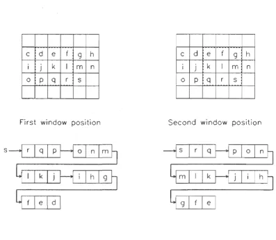
Operation of a pipelined window employing a shift register43
3.3
Operation of Danielsson's variable length shift register44
3.4
Operation of a five element, systolic array, merge sorter47
3.5
A bitonic sorter for eight elements. . .50
3.6
An odd-even transposition sorter for eight elements51
3.7
Block diagram of the circuit for the rank and range filter 545.6 Circuit diagram of the selector cell 5.7 Moore diagram for the reset circuitry
5.8 Floorplan of the bit-serial rank and range filter chip
6.1 The principle of triangulation . . . . 6.2 Light stripe ranging using a conveyor
6.3 The use of an LCD to project patterns onto a scene 6.4 Setup for range mapping using grid coding . . . .
93 95 97
109
111
112 116 6.5 Determining the orientation of a plane from grid element distortion 1187.1 The principle of triangulation . . . 123 7.2 Determination of the patterns for parallel ray grey scale ranging 125 7.3 Determination of the patterns for diverging ray grey scale ranging
7.4 Some of the distortions that can be removed by normalisation 7.5 Range ambiguity due to spatial resolution of the patterns. 7.6 Multiple illumination paths in a concave scene . . . . . 7.7 The object used to test the grey scale ranging method. 7.8 Experimental setup for grey scale ranging. . . . . 7.9 Range map of the test scene before normalisation
B.1 Prototype rank and range filter board. B.2 Prototype chip pinouts . . . . .
C.1 DMA circuit for BISERF board
C.2 Custom chip interconnections for BISERF board. C.3 Custom chip pinouts for BISERF board . . .
128 131 132 135 137 138 139
182 183
Li
f
Tables
2.1 Microsyntax for the LET command . 2.2 Macrosyntax for the LET command.
2.3 A Summary of the Commands Available in HIPS KERMIT.
4.1 Functionality of the rank and range filter chips supplied.
A.l The format of each packet sent by KERMIT . . . . A.2 The format of each packet sent by KERMIT continued A.3 KERMIT state flow table . . . .
A.4 KERMIT state flow table continued . A.5 KERMIT state flow table continued . A.6 KERMIT state flow table continued .
B.l RAFI pin functions . . . . B.2 RAFI pin functions continued B.3 RAFI pin functions continued B.4 RAFI pin functions continued
C.1 BISERF pin functions . . . . C.2 BISERF pin functions continued. C.3 BISERF pin functions continued.
19 21
29
79
167
168
170
171
172 173
175 176
177
178
186
187
cknowledge
nts
I would like to convey my sincere thanks to the following people for their support during the course of this work.
• Dr. R.M. Hodgsonl for his unfailing support, endless enthusiasm and
help-ful comments as my supervisor.
• Mr L.N.M. Edward for his useful suggestions and willingness to assist with technical problems. Mr Edward is solely responsible for the integrated circuit design facilities at the university.
• The staff and post-graduate students of the department for their friend-ship and constructive comments. In particular, Mr M.J. Cusdin for his hardware and software expertise in maintaining the department's High Resolution Image Processing System; Mr A.R. Cox for his software skills, and his help with the KERMIT program; and Miss D.J. Robertson for her meticulous work in wire-wrapping the prototype and bit-serial rank and range filter boards. Also, Mr J.C. Wilson and Mr S.J. McNeill for their suggestions regarding the development of software on the High Resolution Image Processing System; Mr D.G. Bailey for his helpful comments, and his proposal for an integrated circuit implementation of the rank filter; Mr A.L.M. Ng for his part as co-designer of the prototype rank and range filter chip; Mr S.D. MacKenzie and Mr R.D. Clarke for their contributions to the bit-serial rank and range filter chip set; and Mr R.F. Browne, and Mr W.K. Kennedy for many fruitful discussions.2
1 Dr. Hodgson has since been appointed Professor of Information Engineering a.t Massey University.
• The students who worked on final year projects under my joint supervision. These included Mr M.G. Feickert and Mr J.B. Purdey who worked on the Fourier analysis of images of grid coded scenes; Mr A. Ling who worked on the geometrical analysis of images of grid coded scenes; and Mr R. McKay, Mr J. Van den Broek, and Mr W.P. Vickery, who worked on hardware and software for an LCD projection system.
II Austek Microsystems and Mr P.D. Crawley for their assistance in the
com-pletion of this thesis.
• My friends, for their understanding and support.
• My parents and sister, for their love, patience, and encouragement, without which this thesis would not have been possible .
Chapter
Introductio
Far from being expensive tools that were only to be found in well-funded research establishments, computers and computerised machines are now commonplace. They are used in applications ranging from children's toys, domestic appliances, and other consumer goods to desk-top publishing systems, process controllers and industrial parts handlers. Even in the street, computerised machines such as phone boxes capable of charging the correct tariffs for international calls, automatic teller machines that provide banking services 24 hours a day, and petrol pumps that issue precise amounts of petrol are now familiar sights. Yet, the computer is not present everywhere, cannot do everything, and there are many tasks still performed better by humans. Why is this so? What limits the application of computerised machines to tasks? How can these limitations be overcome? To answer these questions, it is useful to see what computers and computerised machines currently do well, what they do poorly, and why. This will illustrate the importance of image processing, and highlight its deficiencies. The work described in this thesis addresses some of these deficiencies.
this reason, computer controlled machinery is being widely used in car assembly plants. By contrast, the processing of primary produce, such as meat, fruit and timber, involves tasks that are not easily automated. For example, gutting and skinning a carcass requires human intervention to guide the process for the different shapes and sizes of carcass. In the same way, skilled labour is required to pick and sort fruit without damaging it. In each case, it is necessary to analyse the situation, and act according to the results of the analysis. The tasks are therefore non-repetitive, and automation is both difficult and unreliable.
Computers and computerised machines are also prevalent in offices and the home. At the office, high quality documents are quickly produced on desk-top computers, and rapidly disseminated to overseas destinations through computer networks, or computer controlled facsimile machines. High speed lifts that record and seek the desired desti-nations of several passengers are common-place, and salaries can now be direct credited to employees bank accounts - all under computer control. At home, video recorders automatically record broadcasts while the owners are elsewhere, and microwave ovens perform pre-programmed cycles as they defrost, and then cook the roast for tea. Again, however, there are areas' that computers have not penetrated. Word processors still use keyboard entry, since computers are unable to reliably interpret either spoken or written messages, and household chores such as cleaning still require human effort.
It is evident that current machines and robots are well suited to performing repet-itive tasks with high precision. They are also capable of performing these tasks in environments that are unpleasant or unsuitable for humans, such as in the extreme pressures of deep sea, or the hostile environment of deep space. However, non-repetitive tasks are not easily automated.
Good examples of the adaptation of the environment to the machine are automatic factories in which work pieces are transported under computerised control from one machine to another as they are shaped and assembled. Typically, each machine has a receiving bay in which a trolley can park in a known position, so that the machine can acquire parts or materials from the trolley and return completed parts to it. Buried cables in the floor of the factory identify 'roads' that the self-powered trolleys can then follow when seeking the next machine. Being under computer control, there is little need for human intervention.
In many situations, machinery must work alongside humans, so the environment cannot be adapted to ideally suit the machine. Under these circumstances, if the tasks are non-repetitive, the machines need human attributes to perform well. In particular, they need the information that humans receive through listening, touching, tasting, smelling, and seeing. With this information, an ability to think, and an ability to act, computerised machines would be able to do almost all the chores currently performed by humans. However, each of these attributes is difficult to mimic in a machine, and despite much research, developments in these areas are still in their infancy.
Of the five senses, sight is one of the most useful for operating in the environ-ment that humans operate in. The fact that much of the human brain is devoted to processing information received by the eyes is strong evidence of this. However, the remaining senses would provide useful input to an autonomous robot also. Taste, for example, would be useful in the quality control of food, and touch would permit controlled gripping of hard, soft, or slippery objects, as well as temperature sensing. Advanced warning of fire or gas leaks, could be achieved if the machine could smell, and if it could hear, it may be able to accept spoken commands, or detect the grating of gears in a machine in need of service. However, sight allows far more diversity. It
has the potential to allow a robot to roam freely without colliding with obstacles or stumbling over uneven terrain; to navigate by identifying and seeking landmarks; to locate, acquire, and assemble objects; to inspect products for imperfections; and ·to grade objects by size or shape. It would also be possible for the machine to recognise when an object is mis-placed or mis-orientated, and to take corrective action.
has been done in image processing in the last decade, but despite the development of many practical systems to solve particular problems, a single system capable of solving any problem that the human visual system can solve, has not yet been created. It is not difficult to see why, when one realizes the limitations that current technology imposes on practical systems. To mimic human vision, it would be necessary to have an image sensor with 100 million light-sensitive elements, and the processing and reasoning power of the human brain. However, many currently available image sensors have no more than 256 thousand elements, and the image data is processed by computers that are far less capable than the brain. Getting such a system to understand what is in the image, and use that knowledge to extract relevant information to solve any particular problem is therefore difficult. The practical systems that do exist, have relied on simplifying the problem to levels that are achievable with current technology. One approach is specialisation, where the system is only required to understand a limited variety of images. This simplifies the problem since it removes the necessity of differentiating between similar scenes if it is known that many of these scenes will never occur in the application. This approach has been used in industry to recognise and determine the orientation of parts, where the number of possible parts is limited. Since only a few parts exist, they can be uniquely and quickly identified by the number of holes in them, the area of their silhouettes, or by other quickly found features.
Another option is to process the image to enhance, rather than identify, features
in the image. A human operator can then make decisions based on the enhanced image. This technique is common in the medical field to enhance X-ray photographs and Computer Assisted Tomography (CAT) scans. A simple example is to map image intensity to colour so that subtle differences in image intensity are more detectable by an observer.
In
these situations, the image processing system is used as a tool, rather than as a complete diagnostics package.When a general purpose image processing system is used, factors such as the size of the image in terms of the computer memory required, the processing speed of the host computer, and the amount of code that the computer must run to process an image, determine the speed at which the image can be processed. On such a system, a functionally correct algorithm may not run quickly enough for the application. To overcome these problems, machine vision systems have made use of contrived lighting and dedicated hardware. Contrived lighting simplifies the processing task by present-ing only relevant information to the sensor, while dedicated hardware can be optimised to perform a particular task quickly. Again, both techniques rely on specialisation for success.
It is evident that significant technological advances will need to be made before machine vision systems approach the versatility of the human visual system, and thereby give machines a useful degree of autonomy. The research performed by the author, and described in this thesis, represents contributions to three areas of image processing. These include the development of software for interacti ve image processing, the design of two integrated circuits and support hardware for rapid image filtering, and a contrived lighting technique for obtaining three dimensional information from a scene.
Chapter 2 describes programs written for the various interactive image processing systems used in the Electrical and Electronic Engineering department of the University of Canterbury. The most ambitious of these was the LET command, which was written to fulfill a need for a user friendly means of manipulating images and other variables on the High Resolution Image Processing System [McNeill 1987]. With the inclusion of this program, the system now operates as a powerful tool for the development of image processing algorithms.
The remaining chapters describe the development of a lighting scheme for deter-mining three dimensional information from convex scenes. Chapter 6 surveys current methods for obtaining three dimensional information, and provides the background for chapter 7, which describes the technique developed by the author.
This thesis therefore describes a collection of projects, each of which addresses one aspect of a limitation of current image processing technology.
During the course of this research, the author wrote or contributed to the following papers.
CD L.N.M. Edward, R.M. Hodgson, M.J. Naylor, A.L.M. Ng, Design of a VLSI
Rank Filter Chip for Real Time Digital Image Processing, Proceedings of
the 5th Australian and Pacific Region Microelectronics Conference,
Tech-nology for Industry, Adelaide, 13-15 May, 1986.
«I R.M. Hodgson, D.G. Bailey, M.J. Naylor, A.L.M. Ng, S.J. McNeill,
Proper-ties, Implementations and Applications of Rank Filters, Image and Vision
Computing, Vol 3, No 1, February, 1985, pp 3-14 .
• R.M. Hodgson, M.J. Naylor, D.G. Bailey, L.N.M. Edward, A Rank and
Range Filter for Image Processing Applications, 2nd International
Confer-ence on Image Processing and its Applications, lEE, London, 24-26 June, 1986 .
• R.M. Hodgson, M.J. Naylor, L.N.M. Edward, The Development of a VLSI
Rank Filter Chip for use in Applied Digital Image Processing, IPENZ
Conference Proceedings, Auckland, 10-14 February, 1986. Also published
as How a Custom Silicon Chip was Designed for an Image Processing
Task - the Design of a Rank Filter Chip, IPENZ Transactions, Vol 14,
Part 2/EMCh, July, 1987, pp 65-70.
@II R.M. Hodgson, J.C. Wilson, M.J. Naylor, (Very) Applied Image
Process-ing at the University of Canterbury, 1st New Zealand Image Processing
• M.J. Naylor, Book review of E.E. Swartzlander(Jr}, VLSI Signal
Pro-cessing Systems, Kluwer Academic Publishers, 1986, 188pp, International
Journal of Electrical Engineering Education, Vol 24, No 3, July, 1987, pp 280-281.
• M.J. Naylor, The Use of Structured Lighting in 3D Image Capture, 2nd New Zealand Image Processing Workshop, University of Canterbury, Christchurch, New Zealand, 20-21 August, 1987.
• M.J. Naylor, Sensors, Image Capture and Preprocessing, Point and Local
Operators, notes for Image Processing for Industry, Agriculture and
Sci-ence, a series of seminars arranged by the Department of Extension Studies,
University of Canterbury, 27-28 November, 1986.
• M.J. Naylor, R.M. Hodgson, An Overview of Range Mapping Techniques,
to be submitted to Image and Vision Computing.
ell M.J. Naylor, R.M. Hodgson, Grey Scale Ranging - A Real Time Range
Chapt
Advanced Software
ritten for
ractive
e
ro
sSlng
"
Syste
.. 1
Introduction
When studying image processing, it is desirable to have access to a good interactive image processing system. This is useful both for learning the principles of digital image processing, and for heuristically developing new algorithms to solve image pro-cessing problems. At the time of my work with the Department of Electrical and Electronic Engineering at the University of Canterbury, there were three such sys-tems. These were the original University of Canterbury Image Processing System or UCIPS [Cady and Hodgson 1980], the High Resolution Image Processing System or HIPS [McNeill 1987] and the VAX Image Processing System or VIPS [Bailey 1985]. In addition to these, two dedicated systems had been developed. One was to determine the size and analyse the shape of kiwifruit [Browne 1986], and another to identify knot-free sections of sawn timber [Clarke 1987J.
processing system, and it now has software for a variety of image processing operations [Cadyet al 1981]. However, since UCIPS does not have a high level language compiler, writing new routines for it is tedious.
HIPS was created as a stand-alone system for the development of machine vision systems. Since HIPS is modular in both hardware and software, it was envisaged that the system could be used to determine the modules needed for a particular applica-tion. Furthermore, the high level language support offered by HIPS would aid the development of software for each application. In practice, HIPS has been used as a general purpose image processing system, and now has a powerful image processing orientated operating system [Wilson 1987]. In addition, it has proved useful as a test bed for image processing hardware developed at the university, such as the rank and range filter boards described in appendices Band C.
The third image processing system, called VIPS, was originally developed to al-low the characteristics of the rank and range non-linear filters to be investigated [Hodgson et al1985,Bailey and Hodgson 1985]. VIPS uses a VAX minicomputer to process the images and an intelligent monitor to display the results. The software consists of a collection of procedures, including a command line parser that allows users to add their own commands. It is therefore possible to write programs that pro-cess images without user intervention, or to add application specific routines to those available to the interactive VIPS user. These features provide a useful environment for the development of image processing algorithms [Bailey and Hodgson 1988].
The following sections describe routines that were written by the author for HIPS.
2.2 . An Introduction to HIP and iRMX86
The High Resolution Image Processing System is a stand-alone computer system de-veloped solely for use in image processing. The details of the system, and the phi-losophy behind its design are described by both McNeill and Wilson [McNeill 1987, Wilson 1987], but the following paragraphs are a summary.
Other boards include a set of three boards that allows images from a television camera to be stored and displayed on a monitor, memory boards that provide one megabyte of RAM, a four channel serial communications board and a disk controller board that controls two eight inch floppy disk drives and a twenty megabyte hard disk drive. In addition to the commercial boards, custom built boards have been built and tested on the system. These include the two rank and range filter boards described in appen-dices B and C, and a linear filter board [Hollows 1988].
The operating system used on HIPS is iRMX86 [Intel 1984], which is a real-time,
mu1ti~tasking system for the 8086 microprocessor family. Real-time operation essen-tially means that the system can be asynchronously driven by interrupts, so that events can be acted upon as soon as they occur. Multi-tasking means that the oper-ating system can support several tasks, or routines that perform specific operations, at one time. Since there is only one processor on HIPS, multi-tasking involves con-trolling the tasks using a mechanism of priorities and interrupts to ensure that only one task is executing at a time. However, it must also maintain the states of the other tasks so that when conditions allow, those tasks may continue execution without loss of data. These two features make iRMX86 ideally suited to industrial control appli-cations where different external events require different responses by the computer. This was one reason for incorporating it into HIPS which is a prototyping system for industrial image processing systems. Another important feature of iRMX86 is that it is modular. In situations where a computer and software are to be installed to control a certain process, only that part of the operating system that is necessary to run the program needs to be installed. The total cost for the installation is therefore lower.
Release six of iRMX86, which is installed on HIPS, offers support for directory trees, provides a simple but powerful set of commands, and uses a command line interpreter that supports type-ahead buffering, and recall of previously entered com-mands. In addition to the operating system, HIPS has a screen editor, and facilities for compiling, linking and debugging programs. The languages currently installed are PASC86, PL/M86 and ASM86, which are iRMX86 versions of Pascal, PL/M, and the 8086 assembler.
command inpuLpathname [preposition outpuLpathname [options}}
or
command inpuLpathname [options}
This provides the user with the option of redirecting the results of operations performed on the file or device specified by inpuLpathname to the file or device specified by
outpuLpathname. Devices include the terminal, the printer, and the floppy disk drives.
Preposition specifies how the results will be sent to the output, and options specify
program parameters. For example,
dir :home:naylor to :Ip: short
performs a directory listing of the directory naylor, which exists in the directory spec-ified by the logical name :home:, and sends the output to the printer, which has the logical name :Ip:. The short option specifies that the listing should only include a short description of each file entry. If instead, the following was typed,
dir :home:naylor after tmp.dir short
then the same directory listing would be appended to the end of an already existing file called tmp.dir. If the preposition over was specified, then the old contents of tmp.dir
would have been overwritten by the directory listing.
When a program is written, it is executed simply by typing its name, so new com-mands can quickly be added to the basic set. System calls exist to parse the command line so that users can write programs that use the standard command structure. The author wrote several commands and utilities for HIPS. The most ambitious was the LET command, which forms part of the Serendip Command Language.
2.
The LET Command -
Equation Parser for
the Serendip Command Language on
S
2.3.1
Introd uction
this program acts as a shell between the user and the iRMX86 operating system. The program contains its own interpreter, but those commands that are not recognised can pass through to the operating system for interpretation. This means that standard iRMX86 commands, user created commands, and SCL specific commands can all be executed from within SCL.
The commands that SCL interprets are placed in memory when SCL is invoked, so these commands do not have to be loaded from disk whenever they are activated. This provides a quicker response to the user, and is one reason for constructing the SCL shell. Included in the SCL shell are commands to display images, read and write to the terminal, set and show the operation modes, and control the flow of SCL programs. There are other image processing commands that must be loaded from disk when run, but these tend to be used less frequently during an interactive session. One SCL command is LET, and the parser for this was designed and written by the author. This command, which inherited its name from the BASIC language function, parses and evaluates arithmetic expressions involving functions of one, two, or more variables of any of the ten SCL variable types.
2.3
the
An important feature of any image processing system is the ability to perform image arithmetic. This raises the question of what is the most user friendly method of expressing what operations are to be performed. After discussions held with potential users of HIPS, the format used in VIPS, where one operation is used per command, and both the destination of the result and the order of operands is not always clear, was discarded in favour of a new approach. The new approach would obey the following criteria .
• The command should accept expressions entered in algebraic form.
@ Allowance should be made to accommodate expressions with more than
one operation, and different operator precedences .
• The command must comply with SCL, by using symbolic references for images and other variables, and supporting SCL syntax for the symbolic references and string constants.
• There should be support for operators that reqUIre one, two, or more operands.
• There should be provision to allow parameters to be specified for the op-erators.
• Users must be able to add their own operators.
It Error checking should be performed, and error reporting should be as
help-ful as possible.
The overall aim of the LET command was to make manipulation of images and other variables simple and straightforward. It was envisaged that most users of HIPS would be familiar with the Pascal programming language, so the expression syntax of LET was designed to conform to the Pascal expression syntax. This syntax uses algebraic notation, supports expressions having several operators, and permits the use of parentheses to change the order of execution. Furthermore, the destination of the result is explicitly stated, and there is no confusion as to what order the operands should be in. Provided that the precedence of operators is understood, the order of execution is also clear. This syntax is therefore ideal for the LET command.
LET should make calls to SCL to create, access and delete variables. This ensures that SCL, which is effectively an environment in which LET and other commands will reside, has full control of the variables. Both of these requirements place restrictions on LET, but are necessary for compatibility.
Another requirement of LET is that it should be able to handle functions of one, two, or more variables. Image processing functions such as inverting an image, and expanding the contrast of an image require only one operand, but functions such as addition require two, and an operation to average several images requires an unknown number of operands. The syntax of LET should be designed to accommodate each of these function types. Related to this is the need to specify parameters for some functions. As an example, if an image is to be thresholded, the threshold value needs to be specified. Similarly, if a convolutional filter is to be applied to an image, the weights and size of the filter window need to be specified. LET should allow parameters of any type to be specified for operators.
User friendliness and expandability should also be designed into LET. User friend-liness is achieved to some extent by employing a familiar format for expressions, but when errors occur, LET should also provide useful error messages. To be expandable, there should be provision for adding new operators to LET and for extending the syntax. These features should give LET the necessary flexibility to be modified rather than rejected by future users.
2.3.3
The Development of the
Command
Although iRMX86 has operating system calls for parsing command lines, these are designed for file handling, and are not suitable for the LET command. For example, there are commands to obtain the input filename, the preposition and the output filename from the command, but an algebraic expression does not obey this syntax. The LET command therefore had to perform its own parsing, and used the operating system only to get characters from the command line.
they are to be executed and the operands of each operation are encountered before the operation itself. In this form, the expression can be evaluated strictly from left to right, since the order of the operations determines their precedence.
A prototype parser was developed that accepted an expression, identified the vari-ables, constants and operations, and shuffled these to place them into reverse polish order. This approach is effectively a bottom up approach that successively groups en-tities into larger enen-tities until only one remains. This remaining entity is the processed expression. An expression such as A
+
B*
C would initially be broken down into the entities A,+,
B,*,
and C. The parser would then identify*
as the highest priority operand, and swap its position with C. The expression BC* would then be treated as a single entity for the next swapping operation involving the next highest priority operation. In this case, A+
BC* would become the single entity ABC*
+
which is a reverse polish form of the en tire expression.Although the program worked, it was not well structured, its operation was diffi-cult to follow, and adding new functions or altering the allowed syntax was not easy. However, the program highlighted problem areas such as differentiating between vari-ables and operations, and error handling, and this information was useful for designing the second program.
2.3
New
An important step in the design of the new LET command was the realization that it performs the same basic functions as a compiler for high level languages such as Pascal. The command must group the characters in the command line into symbols representing variables, constants, or operations; determine the value of the variables and constants and the precedence of the operations; check the syntax of the expression; and then evaluate the expression according to the rules specified by the syntax. These functions are closely related to four of the six stages of compilation that are identified by Aho and Ullman [Aho and Ullman 1972] - the generation of intermediate code and optimisation being less important for compiling a single expression.
• Bookkeeping, which stores or updates information about the entities.
Ie Parsing or syntax analysis, which checks the syntax of the expression.
• Translation to an intermediate code.
• Code optimisation that optimises the intermediate code.
iii Final code generation that generates executable code.
Having established the similarity between the LET command and compilers, the next step was to determine what compilation method should be used. The parsing stage was of most interest, since this determines the type of syntax that can be sup-ported. Aho and Ullman describe several parsing methods, including both full and limited backtracking aJgorithms, table directed algorithms, and one-pass, no backtrack algorithms.
In full backtracking algorithms, the allowed syntax is described in terms of a tree. Each node in the tree describes the type of entity allowed at this point. A path from the root node to a leaf on the tree therefore describes a list of entities that form a valid expression. In top-down parsing, the first entity in the expression being parsed is compared to each of the nodes beneath the root node of the tree. If a match is found, then the second entity is compared to each of the options beneath this node, and so on. If a node is reached where no match is found, then backtracking takes place. This is done by moving back to the previous entity and the previous node, and seeking alternative matches at this level. If no matches are found here, then the algorithm backtracks further up the tree. If the entire tree is searched without successfully matching the expression, then there is an error.
In tabular parsing methods such as that of Earley [Aho and Ullman 1972], the syntax is represented by a set of rules, or productions. One or more of these produc-tions defines a valid equation in terms of other entities. The remaining producproduc-tions define single entities in terms of other entities and/or symbols such as character strings. The parsing starts by forming a table from the set of productions. One table is then produced for each of the entities in the expression to be parsed. Each table contains productions that describe the expression parsed so far, and the entity about to be parsed. A parse is considered valid if the table corresponding to the last entity of the expression contains one production that defines a valid equation, provided that the production does not expect any further entities. This table directed parsing is superior to full backtrack parsing since it permits recursion, works for all context free grammars, and is efficient. However, the algorithm is not easily programmed, and the resulting code would not be self explanatory. For this reason it was dismissed in favour of a more elegant technique called recursive descent compiling [Davie and Morrison 198:1.]. The type of recursive descent compiler to be described is a one-pass no-backtrack compiler. It is an LL(l) parser, which means that it scans the input from left to right, expands the productions describing the syntax from left to right, and looks ahead only one symbol into the expression being parsed. Although this places restrictions on the type of syntax that can be parsed, it simplifies the construction of the parser. Pascal is one example of a language that can be parsed by this type of parser.
The main advantage of this method is the direct relationship between the pro-ductions describing the syntax, and the procedures in the program. If the procedures are given names that describe the entities they define, then the program is self ex-planatory, and is easily adapted to accommodate changes to the syntax. A second advantage is that since procedure calls are used to expand each entity, the context of the parsing before the entity was expanded is restored as soon as control returns from the procedure describing the expansion. This frees the programmer from this task. The third advantage is that error checking can be performed easily.
2.3.5 The Definition of a Syntax for LET Expressions
When defining a language, it is useful to consider the syntax at two levels of complexity [Davie and Morrison 1981]. The microsyntax defines the combinations of ASCII char-acters that form valid symbols such as constants, variable names and operator names. The macrosyntax of a language defines the combinations of symbols that form valid entities such as expressions, binary operations, or vectors. Both syntax types can be described in terms of the Backus Naur Form [Berry 1982]. In this form, angle brackets
<>
surround names that represent the symbols or entities being defined, ::== readsas is defined as, and
I
separates alternative definitions. Braces {} surround items thatcan be repeated zero or more times.
Table 2.1 gives the microsyntax for LET. There are five main symbols: string constants, numbers, operators, identifiers, and the null terminator. String constants must be enclosed in single quotes, or double quotes, or start with a dollar sign. The latter form is for compatibility with Serendip. Numerical constants can be either integer or real, but must start with a numeral. Identifiers are alphanumeric strings that must start with an alphabetical character. The null terminator is the character that marks the end of the string, and is usually the carriage return character. Finally, operators consist of single characters that are not alphanumeric. Note that since the first character of a symbol determines its type, the microsyntax is an LL(l) grammer. This means that recursive descent parsing can be used even at this low level of parsing.
<string> ::== '<str1>' {, <str1»} 1"<str2>"{I<str2>"} I $<str3> <num> ::== <int>
I
<reI><op> ::== I I-I! 1<01 # I $1 % I A I&; I
*
I ( I) I-I = I + I [I {I] I} 1 \ I > 1<1 , 1/ I? I :<id> ::== <letter>{ <idtail>}
<null> ::== ; 1 <null_char> 1 <ret_char> <str1> ::== {<char>
I"}
<str2> ::== {<char> 1 )} <str3> ::== {<char>
I"
1 ,}<int> ::== <digit>{ <digi t>}
<reI> ;:== <int>.{<int>}I<int>.{<int>}E<int>l<int>.{<int>}E-<int> <letter> ::== AIBI ... YIZlalbl ...
ylzl_
<idtail> ::== <digit>{ <idtail>} I <letter>{ <idtail>} <null_char> ::== the character with ASCII value 0
<ret_char> ::== the character with ASCII value 13
<char> ::== <letter> 1 <digit> I <symbol> <digit> :: 0111213141516171819
<symbol> ::== <op> I; I .
Table 2.1: Microsyntax for the LET command
the valid form for an expression, and for the entities that make up the expression. The syntax supports unary, binary and nary operations.
expression more readable since it clearly specifies that the operation operates on the operand.
Functions of two variables, or binary operations, are also supported by LET. The syntax requires that the operation be placed between the operands, and that there be no parameters. However, there is provision for setting up to four levels of precedence on the operators. This allows, for example, the multiply operator to be given higher precedence than the addition operator, so that expressions execute in the order used in Pascal expressions.
The final type of function supported by LET is the unary operator. This type of function was included to accommodate functions of an unknown number of operands. As an example, an nary operator might be used to find the average of several images, or the best match between a template and a set of samples. In this case the syntax requires that the nary operator be followed by a list of operands separated by commas, and enclosed in parentheses. Again, each of the operands may be an expression.
Another feature to note is that LET supports the use of parentheses to change the order of execution of an expression. Again, this is to maintain compatibility with Pascal expressions.
2.3.6
The LET program consists of four parts. They are initialisation, microsyntax parsing, macrosyntax parsing, and expression execution.
<let_proc> ::== <any_var><assign_op><exp><null> <any _ var> ::== <id>
<assign_op> ::==
=
<exp> ::== <exp1>{ <bin4><expl>} <bin4> ;:== <id>
<exp1> ::== <exp2>{ <bin3><exp2>} <bin3> ::== <id>
<exp2> .. <exp3>{<bin2><exp3>} <bin2> ::== <id>
<exp3> ::== <exp4>{ <bin1><exp4>} <bin1> ::== <id>
<exp4> ::== <var_const>
I
«vect_exp»<var_const> ::== <string> I <num> I<id> I <special_op> <vect_exp> ::== <exp>
I
<exp» <exp> I <exp> ) <exp» <exp><special_op> ::== <unary_op><param_list><prep><exp4>
I
<nary_op><var_list> <unary_op> ::== <id><param_list> ::== «param_exp>{,<param_exp>}) 1()I«exp>{,<exp>}) <prep> ::== <id>
<nary_op> ::== <id>
<var_l > ::== «exp>{,<exp>})
I
<var_const> <param_exp> ::== <param_name><assign_op><exp> <param_name> ::== <id>Table 2.2: Macrosyntax for the LET command
system commands with their own commands if desired.
Once initialisation is performed, parsing commences. This is started by calling the procedure that defines an expression. This then calls the relevant procedures in recursive descent fashion to parse the input expression.
unnecessary space characters, and uses the character to determine the type of symbol being read. It then calls the appropriate proced ure to parse the rest of the symboL A special case is the parsing of string constants. In this case, LET permits a variety of forms for strings, but SCL only permits one form. The microsyntax parser therefore performs the necessary conversion. Since the language being parsed is LL(l), the parser reads one symbol ahead of the macrosyntax parsing state.
The macrosyntax parser performs most of the work. It takes the expression syntax definition, and expands it by procedure calls until a production is reached where a symbol is expected. Since the parser knows what it expects, it can interrogate the microsyntax parser to see if the next symbol is the correct one, or to see if it is one of several, if options exist. The latter case occurs when the way in which an entity is expanded depends on the type of the next symbol. An additional responsibility of the macrosyntax compiler is the handling of parameters for unary operators. Since the set-up file for LET contains information on the names of the parameters, the order in which they should occur, and the variable types that are permitted for each parameter, the parser can check the syntax, perform type checking, and place the parameters in the correct order for the unary operator procedure.
Execution of the operations occurs as soon as the operator and its operands are known. This avoids generating intermediate code that must then be executed. It
also simplifies type checking of parameter values for unary operators, when those values are themselves expressions. Since the expression is evaluated as it is parsed, the result, and therefore the type, is known before the unary operator is executed. The operators themselves are procedures that have been linked to the LET and SCL programs. They are executed indirectly through generic routines that represent each of the three operator types. These routines use the unique number, specified in the LET set-up file, that identifies the operator, to execute the relevant procedure. The operands and parameters for the operator are accessed by popping them off a global stack that LET sets up as it performs the parsing. Most of the system operators were written by Purdey and Wilson [Wilson 1987], although the author added a rank filter routine, and a routine to interface to the custom built board for the prototype rank filter chip.
musLbe and have. These routines operate on symbols only, and serve as a means of flagging an error if the symbol is not the expected one, or simply checking to see if the symbol is the expected one. It will be seen from the syntax diagram that many of the productions have optional expansions. The way in which these productions are expanded is determined by the type of the next symbol in the input string. The have
function checks to see if the next symbol in the input string is what is desired. If it is, the function returns TRUE, and forces the next symbol to be read. If the string is not what is expected, then have returns FALSE, and the next symbol is not read. The
musLbe routine is used when there is no other valid choice in the production. If the
next symbol is the one that is expected, then musLbe forces it to be read, and returns control to the calling procedure. If the next symbol is not the required one though, then an error is flagged. A version of the have and musLbe routines is described in the text by Davie and Morrison.
The final consideration of the LET command is error handling. The most common forms of errors when running LET are incorrect syntax, and incorrect parameter types. Incorrect syntax occurs when the musLbe routine finds that the next symbol is not what is expected. The error handler could flag this by simply notifying the user of what was expected, but this is insufficient. Often the musLbe routine is only called after several calls to have have failed. This means that more than one option is valid, not just the one that caused the error. LET solves this problem by maintaining a list of symbols that have been specified in the calls to have. If have is successful, then this list is cleared, so that only the relevant information is retained. Now if musLbe
2.3.7
.
ISCUSSIOn.
The LET program now occupies over 200 kilobytes, but it is well structured. One drawback is that it takes fifteen seconds to load the LET set-up file. This is because the set-up file now contains entries for over sixty commands, and each of these must be interpreted and stored internally by LET. However, the setting up of LET is now performed when SCL is invoked, so that this overhead is not incurred each time the LET command is run. The execution speed of the LET command is largely dependent on the operations being performed. Adding two integers takes half a second, while adding two images of 256 by 256 by eight bits takes sixteen seconds. When performing image operations therefore, the parsing time, which is less than half a second, is insignificant.
2.4
CLEAN - A Rout
to Sort iRMX86
irectories
In addition to the LET command, the author also wrote several utilities for HIPS, one being the CLEAN routine. One of the problems with the HIPS operating system is that directory listings are not alphabetically sorted, so it is often difficult to locate the file of interest in a listing. The CLEAN routine was written to overcome this difficulty. The routine converts all filenames in the specified directory to lower case, and all directory names in the directory to upper case. It also puts the entries in alphabetical order. The program was written in PASC86, which is Intel's version of Pascal, and is invoked by typing
clean inpuLpathname
where inpuLpathname is the name of the directory to be cleaned.
the system call for renaming files to perform the operation. In this case, the operating system performs the update on the directory file, so an explicit write is not needed.
To change the case of a directory entry in the iRMX environment requires an intermediate step. Since the operating system does not differentiate between upper and lower case when reading a file name, renaming a lower case name to an upper case name causes an error and the operation is not performed. To force the change, the user must change the name to some different temporary name, and then change it back to the correct name with the desired case.
Changing the order of entries in the directory listing is even more difficult. Re-naming files to the same directory has no effect on the order in which the files are listed. One way around this is to create a new directory, rename the files to this di-rectory, then rename the new directory over the old directory. \tVhen a new directory is created, any files that are added to that directory are listed in the order in which they were added. This therefore gives the key to a method of cleaning up directory listings.
The program is slow to run because it has to access the hard disk to get information on each file, and to rename each file. To clean a directory containing ten files takes fifteen seconds.
2.5
IRTREE - A Program to List
iRMX86
Directory Trees
Another weakness of the iRMX operating system is the inability to perform a recursive directory listing on directories within directories. Such a feature is useful for main-taining a large system conmain-taining many files, because it allows the operator to locate particular files of interest. DIRTREE, which was written in PL/M86 by the author, performs this operation.
The program is invoked by typing
dirtree inpuLpathname [preposition outpuLpathname]
where inpuLpathname is the name of the root directory that encompasses all the files to be listed, and preposition specifies how the listing will be sent to the destination specified by outpuLpathname. DIRTREE lists the names of the files in each directory in five columns. It does not list invisible files, and does not support any options.
The first step in the DIRTREE program is to move to the directory specified by the input pathname. A re-entrant procedure then checks to see if the current file is a directory. If it is, then the procedure lists the entries in the directory, and calls itself repeatedly with the current file set to each of these entries in turn. After the last file in the list has been processed, control is returned to the calling procedure. If the current file is not a directory, then control is immediately returned to the calling procedure. This recursive routine therefore lists all files in all directories below that specified by the input pathname. The program sends the results to the destination specified by
outpuLpathname, and then operates on each remaining inpuLpathname in turn.
DIR command with the specified options for each directory found. However, each time DIR was invoked, it was loaded in from disk, which again meant the operation was unacceptably slow. The simple DIRTREE command that is currently in use lists eighty files from a directory with three sub-directories in 23 seconds.
2.6
A
S Utility
for Transferring Files Over
erial Link
2.6.1
Introduction
A feature that was added to HIPS at an early stage was a serial communications link between HIPS and the VAX. A program called ACL, for Asynchronous Com-munications Link, allowed the user to pass files between the two computers, and a second program called ONLINE allowed HIPS to be used as a terminal for the VAX [McNei111987]. ACL was initially used to transfer files that had been written using the screen editor on the VAX down to HIPS. It also permitted files on HIPS to be transferred to the VAX for printing. However, HIPS now has its own printer and a screen editor, so these uses of the link are less common. The main use of the link now is for transferring image files from HIPS to the VAX for use by VIPS. Since HIPS is the only facility in the department for capturing high resolution images in computer readable form, the HIPS to VAX link is essential.
2.6.2 A Description of KERMIT
KERMIT is a public domain program for transferring files between computers over a serial link. The original protocol was defined by Frank da Cruz and Bill Catchings in 1981 at Columbia University, New York, but additions have been made to it by several people. Since it is public domain software, there is no charge for copying or modifying the program, provided it is not used to make a profit. Versions of the program exist for several machines, and can be obtained from the Centre for Computing Activities, Columbia University, New York 10027, USA.
The University of Canterbury obtained a large number of versions, but none were directly suited to iRMX and HIPS. The author therefore took a rudimentary PL/M80 version of the program, corrected several errors in it that were incompatible with the KERMIT protocol, made it suitable for running on HIPS, and upgraded it to incorporate several more KERMIT features.
The full KERMIT protocol is available from Columbia University [Cruz 1984a], but it is summarised in appendix A. Briefly, data is sent in packets that consist of a few bytes of header information, followed by the data itself. The sending computer sends a packet, and then waits for a response. If the receiving computer responds by sending the correct response packet, then the sending computer sends the next packet.
If the response is incorrect, or no response is received within the timeout period, then the current packet is sent again. Only if the number of retries exceeds the retry limit, will the computer abort the attempt to send the file. In practise, this situation usually means that either the serial link has been unplugged, or the receiving computer has not been set up to receive the file. Provided the link is operating, the packet headers contain sufficient information for both computers to exit gracefully from fatal errors such as insufficient room to create the destination file, or insufficient privilege to read the source file.
2.6.3
How the HIPS Version of KERMIT is Used
KER-,
BYE Exits host server and logs out CONNECT Links terminal to selected port EXIT Exits from iRMX-KERMIT
FINISH Exits host server to operating system GET pl[ TO p2] Receives a file from host server
GIMG pl[ TO p2] Receives a file from VAX operating system HELP Prints out this table
LOGOUT Exits host server and logs out RECEIVE Receives a file SENT from host SEND Sends a file to host server SET BAUD num Sets baud rate from 300 to 9600 SET DEBUG mode ! Sets debug mode ON or OFF
SET PORT num Sets port number from 1 to 4
SIMG pl[ TO p2] Sends a file to V AX operating system
[image:41.595.78.512.83.449.2]Where pl, p2 are source and destination file lists, and p2 = pl by default. Table 2.3: A Summary of the Commands Available in HIPS KERMIT
MIT commands. These commands are described in the next few paragraphs.
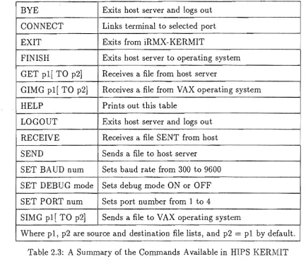
The file transfer utility is invoked by typing KERMIT without any pathnames or options specified. The program responds by prompting the user with iRMX-KERMIT>. Commands are typed in upper or lower case, and are entered by typing the <return> key. Only as many letters as are necessary to uniquely define a com-mand need be typed in. The comcom-mands available are those listed in table 2.3, which can be obtained by entering the HELP command.
types AE to exit back to iRMX-KERMIT, and enters SEND srefile, where srefile is the
name of the file to be sent. This establishes the link, and transfers the file to a file with the same name on the other computer. When complete, both machines return to the prompt mode of KERMIT. A file can be received from the other computer by entering SEND srefile after connecting to the other computer, and then returning to
HIPS and entering RECEIVE before the other computer times out.
The second method is for transferring files to or from a computer that has a version of KERMIT that supports SERVER commands. In this case, the HIPS user enters CONNECT and logs on to the other computer as before. KERMIT is then invoked on the other machine, and SERVER entered. The user then types AE to return to iRMX-KERMIT. If the user then enters SEND filename, then filename is read from
HIPS and sent to the other computer, where a file with the same name is created. Alternatively, the user may enter GET filename to transfer the contents of filename
on the other computer to a new file of the same name on HIPS. In both cases, the SERVER on the other computer interprets the packets being sent, and automatically switches to the appropriate mode. On completion of the transfer, the other computer reverts to the SERVER mode.
The HIPS version of KERMIT is enhanced in that it allows the user to specify both the source and destination file names for the SEND and GET commands. For example, SEND srefile TO dstfile reads srefile and sends the contents to dstfile on
the other computer. Similarly, GET srefile TO dstfile reads srefile form the other
computer, and sends the results to dstfile on HIPS. This is useful if different filenames are required, or if directories other than the default directories are to be used.
At the completion of a transfer, the user must CONNECT to the other computer, exit from KERMIT, and log off. If however the other computer is in SERVER mode, then the user can simply enter BYE or LOGOUT from iRMX-KERMIT instead. An-other command FINISH causes the An-other computer to exit from KERMIT if it was in SERVER mode, but it does not log off.
The default transfer rate of KERMIT is 9600 baud, but this can be altered using the SET BAUD num command where num is a standard baud rate from 300 to 9600
baud. The SET PORT num command is a HIPS specific command that allows the
default, port one is selected.
There are two classes offile that KERMIT can transfer. These are text files, which contain only printable characters, such as document files and program sources, and binary files such as executable code. To support these two types of file, KERMIT has a TEXT mode of operation and a BINARY mode.
In TEXT mode, the aim is to send the file so that it can be printed out on the destination machine. Since different machines have different text file formats, the KERMIT protocol specifies an intermediate text file format for transmitting the data. In this format, data consists of seven-bit ASCII characters arranged in lines that are terminated by carriage-return line-feed pairs. KERMIT converts between this intermediate standard, and the text file structure used on the computer it runs on. The net result is that if a file can be printed out on one machine, then after transferring it to another machine using KERMIT, it will appear the same if it is printed out on that machine.
The other mode of operation is BINARY mode. In this mode, data consists of eight-bit characters, so the state of the eighth bit must be maintained. In this mode, the data is not modified so that if the file is transferred to a different system and back again, the returned file is the same as the original.
On HIPS, text files conform to KERMIT's intermediate format, so no conversion is necessary. For this reason, HIPS KERMIT does not differentiate between TEXT and BINARY modes. However, in VAX text files, each line contains a word indicating the length of the line, and a null character at the end of the line if the length is odd. This null character is used to pad out the number of bytes in the line to an even number. Since this differs greatly from the intermediate KERMIT format, VAX KERMIT performs the necessary conversions between the two formats when in TEXT mode.
resemblance to the image line lengths. To overcome this difficulty, the author wrote a conversion program that reads the BINARY file produced by KERMIT and converts
it to the correct formaL It does this by reading the characters into a bu