13/9 Lifting Wavelet Transform based Reversible Data
Hiding
Subash N.
Research Scholar, RGMCET
JNTUA, Ananthapuramu,
Andhra Pradesh, India
Jayachandra Prasad T.
Dept of ECE, RGMCET
JNTUA, Ananthapuramu
Andhra Pradesh, India
Sumalatha V.
Dept of ECE
JNTUA College of Engineering
Ananthapuramu, Andhra
Pradesh, India
ABSTRACT
In this paper a novel 13/9 lifting scheme for hiding data has been implemented. Lifting schemes are the part of wavelet transformation which decomposes image into wavelet coefficients using basis function for analyzing multi-resolution images. Lifting scheme is preferred for data hiding because the operations are performed in spatial domain by simple LSB replacement. The 13/9 lifting scheme contains 13 low pass and 9 high pass coefficients. As more information in image lies at low frequency components, 13/9 implemented lifting scheme contains 13 low-frequency components, whereas 5/3 lifting scheme contains 5 low frequencies and 9/7 lifting scheme contains 9 low frequencies. Simulation results show that the payload and average PSNR are increased than the existing methods with the PSNR 58.17 dB at bit rate of 0.05 for Lena image.
General Terms
Image Processing, SecurityKeywords
Reversible Data Hiding, Encryption, Lifting Wavelets, Steganography.
1.
INTRODUCTION
With the rapid change in communication media maintaining security and safety became a challenging task. Recently attention was drawn to attain reversibility in images known as Reversible Data Hiding (RDH) which is branch of steganography. It hides data, images, audio or video formats into another text, image, audio or video formats. It aims at recovering the input image from the data hidden image when secret message is extracted. Due to this RDH became interesting area for the researchers in the field of image processing. They provided different algorithms for the improvement of the image quality and attaining reversibility. These methodologies are categorized into Spatial and Transform domain approaches. In spatial domain, one of the simplest technique is least significant bit (LSB) replacement. Based on this process RDH schemes are further classified into four types: 1) Difference Expansion 2) Histogram method 3) prediction methods 4) Interpolation Algorithms.
Tian [1] introduced difference expansion method with high capacity and less distortion. The disadvantage is binary map size was not known and low compressibility of the location map. To over this problem Alattar [2] used vectors as difference expansion and improved capacity. Hu et al. [3] presents a variant DE technique which improved the compressibility of the location map with increase in payload for different image types. In 2009 Yuan et al. [4] implemented an algorithm to hide data into embedding area and secondary information areas in which data was hidden in
embedding areas and overhead bits are inserted into secondary information area. Ni et al. [5] implemented data hiding based on histogram by calculating minimum and maximum points and made some modification to the pixel gray values to embed data and proved that this method can embed data up to 80kb while maintaining high visual quality than existing methods. Tseng and Hsieh [6] proposed two methods, in the first method histogram was taken for sub-block while maximum points remain unmodified to pull out the embedded data and in the second method to decrease the overhead information size shifting operation is performed which improves the image quality > 48dB. Thodi and Rodriguez [7] used both DE and histogram methods, and developed a new technique by reducing the distortion occurred in difference expansion to attain reversibility. W.L.Tai et al. [8] proposed novel method on histogram modification using binary tree method and improved the payload with low distortion.
Researchers later combined histogram based methods with prediction methods. 2008 Piyu Tsai et al. [9] proposed an RDH method on predictive coding and improved the hiding capacity, which is three times larger than the normal histogram method with improved image quality of 1.5dB. Vasiliy et al. [10] used technique of sorting and prediction errors for data embedding to attain low distortion and the histogram shift scheme was implemented for decreasing the location map size and increase the capacity further. Chin-Feng et al. [11] implemented location map free region for input image recovery with minimal visual distortion. Xiaolong Li et al. [12] proposed a novel method for hiding data using pixel-value-ordering to improve the performance in PSNR. Boet al. [13] applied partial differential equation predictor function for sub-blocks which gives less distortion.
Lixin Luo et al. [14] worked in the sub-domain of interpolation in RDH by embedding data into variation between the interpolation error and corresponding pixel values and achieved payload of 84,050 bits with PSNR of 48dB. Wang et al. [15] proposed RDH technique in spatial domain for enhancing the image quality by classifying elements as wall and non-wall pixels. Yalman and Akar [16] proposed a novel method for hiding and increased payload up to 6, 02,406 bits at rate of 0.766 bpp for color image of Lena with PSNR 42.43dB and further data hiding capacity can be increased by applying NMI more than once.
improved PSNR. Yang et al. [19] implemented integer wavelet transform for hiding data in LH and HL sub-bands and attained a high average payload of 78,643 bits with average PSNR of 49.49dB. Lin [20] implemented DCT and used high frequency components to embed secret data and obtained payload of 1, 52,389 bits with PSNR 36.44 dB for 8x8 block size. Engin Avci et al. [21] presented a wavelet domain based method and enhanced the visual quality to 52.16dB with payload capacity of 1,17,160 bits. Fan Li et al. [22] implemented a RDH scheme in frequency domain using Haar Transform and improved the performance in PSNR and payload. Kede Ma et al. [23] proposed method for hiding data in encrypted images and attained reversibility.
In this paper, we implemented a 13/9 lifting scheme by embedding data into the Inverse transformed images and observed that this method performs well in payload and average PSNR when compared to existing techniques. From the simulation results, our 13/9 lifting method attains high PSNR when compared to other methods, such as Ni et al [5], Thodi and Rodriguez [7], Tai et al [8] and Kede Ma et al [23].
The broad categories of the paper are as follows: Section 2 described about 5/3 and 9/7 lifting schemes. Section 3 presents algorithm for 13/9 lifting scheme and embedded data into it. In section 4 we present the Simulation results from which necessary Conclusions are drawn in Section 5.
2.
RELATED WORK
Wim Swelden developed lifting concept in spatial domain. It breaks the poly phase matrices into a sequence of superior and inferior matrices. A new lifting scheme was constructed using bi-orthogonal wavelets with the poly phase matrix as:
P z =
h
eg
eh
og
o(1)
The factorizations aim at representing the poly phase matrix as a set of superior and inferior matrices as [24]:
𝑃 𝑧 =
1
𝑆
𝑖(𝑧)
0
1
1
0
𝑡
𝑖(𝑧) 1
𝐾
1
1
1/𝐾
𝑚
𝑖=1
(2)
Where K- Scaling factor.
𝑆𝑖(𝑧),𝑡𝑖(𝑧) - polynomials with primal and dual lifting
stages
The main steps involved in lifting scheme are: Splitting, Prediction and Updating.
The different lifting scheme based wavelets existing in literature are 5/3 and 9/7.
2.1
5/3 Lifting Scheme:
5/3 lifting scheme was introduced by LeGall. It contains 3 high pass and 5 low pass tap filters. This is the simplest process of decomposing the image into high and low- frequency components. It contains two vanishing moments.
The lifting factors of
P z
( )
are given below:𝑃 𝑧 = 1 1 0 2(1 + 𝑧) 1
1 −1
4(1 + 𝑧 −1)
0 1
1 0
0 2 (3)
The filter coefficients for 5/3 lifting scheme [25] are:
𝐻 𝑛 = 𝑥 2𝑛 + 1 +1
4 𝑥 2𝑛 + 𝑥 2𝑛 + 2 (4)
𝐿 𝑛 = 𝑥 2𝑛 −1
2 𝐻 𝑛 + 𝐻(𝑛 − 1) (5) Where H and L are maximum and minimum frequency components. The performance of 5/3 lifting scheme is better in PSNR than other existing wavelets where as poor compression ratio or the hiding capacity is low. To increase embedding rate 9/7 lifting scheme was designed.
2.2
9/7 Lifting Scheme:
The algorithm designed for JPEG2000 standards uses a set of 9 low pass and 7 high pass filter coefficients with 4 vanishing moments in image compression domain. The filter is factorized as follows [24]:
𝑃 𝑧 = 1 𝛼 1 + 𝑧−1
0 1
1 0
𝛽 1 + 𝑧 1 1 𝛾 1 + 𝑧
−1
0 1
1 0
𝛿 1 + 𝑧 1
00
1 (6)Where 𝛼, 𝛽, 𝛾, 𝛿- are filter coefficients,
- Scaling factorIt is found that the 9/7 methodology is more efficient due to better scaling factor with increase in the payload size when compared to 5/3 lifting scheme but visual quality has degraded. So achieving high image quality with high payload became a challenging task. In order to address this issue a new 13/9 lifting scheme is proposed which can overcome the design drawback of the earlier lifting schemes.
3.
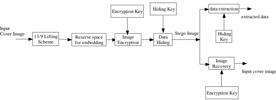
PROPOSED METHOD
13/9 Lifting Scheme
Reserve space for embedding Input
Cover Image
Image Encryption Encryption Key
Data Hiding Hiding Key
Stego Image
data extraction
Hiding Key
Image Recovery
Encryption Key
extracted data
[image:3.595.62.532.70.241.2]Input cover image
Fig 1: Frame work implementation
3.1
Algorithm for 13/9 Lifting Scheme
The algorithm for 13/9 scheme is presented. This algorithm contains two phases: forward and reverse transform.3.1.1
Algorithm for forward transform
The algorithm for forward transform contains both: Row transformation and Column transformation.
i) Row transformation:
Consider r as the row number, c as column number and p as c-1.
a) For every row The first column
lo()2(r,2c-1)+6(r,2c)+2(r,2c+1)-(r,2c+2)
hi() 2(r,2p+1)-(r,2p+2)
While last column
lo()-(r,2c-2)+2(r,2c-1)+6(r,2c)
hi()-(r,2p)+2(r,2p+1)-(r,2p+2)
and remaining columns
lo()-(r,2c-2)+2(r,2c-)+6(r,2c)+2(r,2c+1)-
(r,2c+2)
hi()-(r,2p)+2(r,2p+1)-(r,2p+2)
ii) Column Transformation a. For each column
The first row
a()2(2r-1,c)+6(2r,c)+2(2r+1,c)-(2r+2,c)
h()2(2p+1,c)-(2p+2,c)
v()2(2r-1,c)+6(2r,c)+2(2r+1,c)-(2r+2,c)
d()2(2p+1,c)-(2p+2,c)
While last row
a()-(2r-2,c)+2(2r-1,c)+6(2r,c)
h()-(2p,c)+2(2p+1,c)-(2p+2,c)
v()-(2r-2,c)+2(2r-1,c)+6(2r,c)
d()-(2p,c)+2(2p+1,c)-(2p+2,c)
and remaining rows
a()-(2r-2,c)+2(2r-1,c)+6(2r,c)+2(2r+1,c)-
(2r+2,c)
h()-(2p,c)+2(2p+1,c)-(2p+2,c)
v()-(2r-2,c)+2(2r-1,c)+6(2r,c)+2(2r+1,c)-(2r+2,c)
d()-(2p,c)+2(2p+1,c)-(2p+2,c)
In the column transform „a‟ and „v‟ holds the filter samples of low pass where as „h‟ &„d‟ holds high pass filter samples.
3.1.2
Algorithm for reverse transform
Here for the column transform, the components a and h are combined to X and the components v and d combined to Y. Finally X and Y are combined to W.
i) Inverse Column transformation
For each column
The first row
m(1st Half) 6X(2r-1,c)+2X(2r, c)-X(2r+1,c)
m(2nd Half) -X(2r-1,c)+2X(2r,c)-X(2r+1,c)
n(1st Half) 6Y(2r-1,c)+2Y(2r,c)-Y(2r+1,c)
n(2nd Half) -Y(2r-1,c)+2Y(2r,c)-Y(2r+1,c)
While last row
m(1st Half) -X(2r-3,c)+2X(2r-2,c)+6X(2r-
1,c)+2X(2r,c)
m(2nd Half)-X(2r-1,c)+2X(2r,c)
n(1st Half) -Y(2r-3,c)+2Y(2r-2,c)+6Y(2r-
1,c)+2Y(2r,c)
n(2nd Half) -Y(2r-1,c)+2Y(2r,c)
and remaining rows
m(1st Half) -X(2r-3,c)+2X(2r-2,c)+6X(2r-
1,c)+2X(2r,c)-X(2r+1,c)
m(2nd Half)-X(2r-1,c)+2X(2r,c)-X(2r+1,c)
n(1st Half) -Y(2r-3,c)+2Y(2r-2,c)+6Y(2r-
n(2nd Half) -Y(2r-1,c)+2Y(2r,c)-Y(2r+1,c)
ii) Inverse Row Transformation
For every row
The first column
x(1st Half) 6W(r,2c-1)+2W(r,2c)-W(r,2c+1)
x(2nd Half)-W(r,2c-1)+2W(r,2c)-W(r,2c+1)
While last column
x(1st Half) -W(r,2c-3)+2W(r,2c-2)+6W(r,2c-
1)+2W(r,2c)
x(2nd Half)-W(r,2c-1)+2W(r,2c)
and remaining columns
x(1st Half) -W(r,2c-3)+2W(r,2c-2)+6W(r,2c-
1)+2W(r,2c)-W(r,2c+1)
x(2nd Half)-W(r,2c-1)+2W(r,2c)-W(r,2c+1)
3.2
Algorithm for Encryption
Encryption is the means of transforming the image into indecipherable form. As security is concern for digital images, encrypting protects image content from malicious attacks. For encryption two different keys are considered: i) Symmetric (or) private key ii) asymmetric (or) public and private key. In the first case, single key is used for encryption and decryption while separate keys are used in the second case. The encryption algorithm includes the following steps.
Step1: Initialize the 8-bit cover image I and acquire its dimension m x n.
Step 2: Generate the symmetrical key to be shared.
Step 3: Generate the random sequence using symmetrical key, denoted as r.
Step4: Perform bit wise operation for the input image I and random sequence r given as:
𝐼1= 𝐼 ⊕ 𝑟, where 𝐼1 is the Ciphered matrix Step 5: Repeat step 2- 4 for all pixels.
It is adapted exact reverse process for decryption. Fig. 2 shows the Lena and its encrypted and decrypted images.
Fig 2: a) Lena b) encrypted form c) decrypted image
3.3
Data Hiding Algorithm
Once the encryption part was done, the hider starts embedding data as follows:
Step1: Read the image 𝐼1 of size h x w.
Step2: Segment 𝐼1 into smaller blocks of size p x p such that
𝑢 − 1 . p + 1 ≤ ℎ ≤ 𝑢. p
𝑣 − 1 . p + 1 ≤ w ≤ 𝑣. p
Where 𝑢 and 𝑣 are positive integers.
Step 3: Divide 𝑝2 pixels of every block as 𝑝
𝑜 and 𝑝1 randomly using hiding key.
Step 4: If binary 0 is to be inserted, then change pixels in 𝑝𝑜 by three positions.
𝐼1′= 𝐼 , ℎ, 𝑤 𝜖 𝑝ℎ,𝑤 ,𝑘 𝑜𝑎𝑛𝑑 𝑘 = 0,1,2
Step 5: If binary 1 is to be inserted, then change pixels in 𝑝1 by three positions.
𝐼1′= 𝐼 , ℎ, 𝑤 𝜖 𝑝ℎ,𝑤 ,𝑘 1 𝑎𝑛𝑑 𝑘 = 0,1,2
Other encrypted bits remain unchanged.
3.4 Extraction algorithm
After the embedding process is done, the extraction of embedded data is explained in the following steps:
Step 1: Apply discrete wavelet transform for the stego image and obtain four sub-bands as LL, HL, LH and HH.
Step 2: perform zigzag scan order for HL, LH and HH.
Step 3: Exclusive-OR operation is performed between random sequence generator r and decrypted image denoted as 𝐼1′.
Step 4: If the inserted bit is 0 and belongs to pixel 𝑝𝑜 , then the 3 LSB positions are decrypted as:
𝐼′= 𝑟 ⊕ 𝐼1′= 𝑟 ⊕ 𝐼 = 𝑟 ⊕ 𝐼 ⊕ 𝑟ℎ,𝑤 ,𝑘 = 𝐼
Step 5: If the inserted bit is 1 and belongs to pixel 𝑝1, then the bits are decrypted as in step 4.
Step 6: Repeat step 3- 5 till embedded data is extracted.
4.
SIMULATION RESULTS
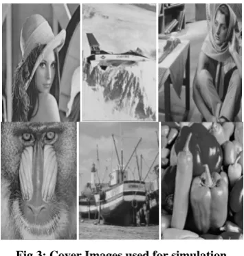
[image:4.595.340.518.498.685.2]The simulation analysis and the results for the proposed methodology is found to be effective for 512 X 512 cover images of “Lena”, “Airplane”, “Barbara”, “Baboon”, “Boat” and “Peppers” are shown in Fig. 3.
Fig 3: Cover Images used for simulation
In this study the parameter used to measure the visual quality with respect to the stego image is PSNR. The PSNR of any resultant image can be calculated using MSE is given in eq (7)
𝑃𝑆𝑁𝑅 = 20𝑙𝑜𝑔10 255
[image:4.595.57.284.571.674.2]Where
𝑀𝑆𝐸 = 1
𝑀𝑥𝑁 𝐼 𝑖, 𝑗 − 𝐼 ′(𝑖, 𝑗) 2 𝑁
𝑗 =1 𝑀
𝑖=1 (8)
𝐼 𝑖, 𝑗 - cover image and 𝐼′(𝑖, 𝑗) - Reconstructed image
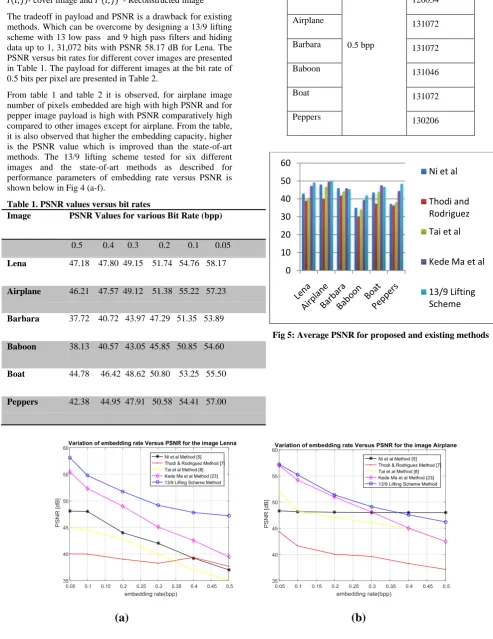
The tradeoff in payload and PSNR is a drawback for existing methods. Which can be overcome by designing a 13/9 lifting scheme with 13 low pass and 9 high pass filters and hiding data up to 1, 31,072 bits with PSNR 58.17 dB for Lena. The PSNR versus bit rates for different cover images are presented in Table 1. The payload for different images at the bit rate of 0.5 bits per pixel are presented in Table 2.
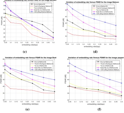
[image:5.595.319.541.70.449.2]From table 1 and table 2 it is observed, for airplane image number of pixels embedded are high with high PSNR and for pepper image payload is high with PSNR comparatively high compared to other images except for airplane. From the table, it is also observed that higher the embedding capacity, higher is the PSNR value which is improved than the state-of-art methods. The 13/9 lifting scheme tested for six different images and the state-of-art methods as described for performance parameters of embedding rate versus PSNR is shown below in Fig 4 (a-f).
Table 1. PSNR values versus bit rates
Image PSNR Values for various Bit Rate (bpp)
0.5 0.4 0.3 0.2 0.1 0.05
Lena 47.18 47.80 49.15 51.74 54.76 58.17
Airplane 46.21 47.57 49.12 51.38 55.22 57.23
Barbara 37.72 40.72 43.97 47.29 51.35 53.89
Baboon 38.13 40.57 43.05 45.85 50.85 54.60
Boat 44.78 46.42 48.62 50.80 53.25 55.50
Peppers 42.38 44.95 47.91 50.58 54.41 57.00
Table 2. Payload for different images at 0.5 bit rate
Images Bit Rate Payload (bits)
Lena
0.5 bpp
126034
Airplane 131072
Barbara 131072
Baboon 131046
Boat 131072
Peppers 130206
Fig 5: Average PSNR for proposed and existing methods
(a)
(b)
0
10
20
30
40
50
60
Ni et al
Thodi and
Rodriguez
Tai et al
Kede Ma et al
[image:5.595.47.541.109.749.2](c)
(d)
[image:6.595.96.519.79.462.2]
(e)
(f)
Fig 4: Comparison of Embedding Rate versus PSNR over six different images: a) “Lena” b) “Airplane” c) “Barbara” d) “Baboon” e) “Boat” f) “Peppers.
Table 3. Average PSNR of the proposed and existing methods for six cover images.
Method
Average PSNR (dB)
Lena Airplane Barbara Baboon Boat Peppers
Ni et.al 43.04 48.09 46.09 35.07 43.64 37.24
Thodi et.al 39.04 40.17 41.89 29.99 37.42 36.42
Tai et.al 40.72 46.83 44.21 34.19 44.06 38.21
Kede Ma et.al 47.31 49.64 45.94 39.44 47.62 44.45
13/9 Lifting Scheme 51.46 51.12 45.82 45.50 49.89 49.53
From Fig 4 (a)-(f) the results are compared with other RDH methods of Ni et al. (2006), Thodi and Rodriguez (2007), Tai et al. (2009) and Kede Ma et al. (2013). These methods either use Difference Expansion (DE) or the histogram-based scheme for single embedding. Histogram based scheme gives high image quality while limiting the payload where as in DE scheme higher embedding capacity is possible with image distortion compared to histogram schemes. Fig 4 presents the results of embedding rate versus image quality and makes clear interpretation that proposed method achieved high visual quality with better embedding capacity. Taking the image “Lena” into consideration, it has attained higher visual quality of 58.17 dB for embedding rate of 0.05 bpp and still
maintained PSNR of 47.18 dB for 0.5 bpp. The 13/9 lifting scheme out performs well for all the six test image in embedding capacity and image quality compared to other state-of-art methods.
[image:6.595.310.500.83.263.2] [image:6.595.52.542.497.619.2]reason is as it contains large areas of complex textures which are to be further rectified.
5.
CONCLUSION
In this section results are summarized. Firstly, a novel 13/9 lifting scheme was implemented with 13 low pass and 9 high pass filters and then embedded data into that image using hiding algorithm and extracted the data from the images without distortion. When compared to state-of-art methods our method out performed well in payload as well as image quality with PSNR up to 58.17 dB and the average PSNR is larger than the existing methods which is equal to 45.50
-51.46 dB for all the test images. The simulation results shows that the proposed 13/9 lifting scheme gives better results in terms of the embedding capacity and PSNR value. In future this work can be extended with embedding rates greater than 1.5 bpp with better image quality.