BBN Computer
L
I
I I
I
I
I
Advanced Graphics Terminal
User's Guide
and
BitGraph
Advanced Graphics Terminal
. User's Guide
Document Number 0320001 Revision Number 3.0 May 1983
The information in this document is subject to change without notice and should not be construed as a commitment
by BBN Computer Corporation. While we make every effort to ensure the accuracy and completeness of all our
publications, BBN Computer Corporation can assume no
responsibility for the consequences to users of any errors that may remain.
Copyright c 1983 by BBN Computer Corporation.
Printed in the United Statis of America.
The Reader's Comments form on the last page of this
publication requests your critical evaluation to help us prepare future documentation.
Printing History:
first revision, March 1982; second revision, November 1982; third revision, June 1983.
The following are trademarks of BBN Computer Corporation:
BitGraph C Machine InfoMail
UNIX is a trademark of Bell Telephone Laboratories
The following are trademarks of Digital Equipment Corporation:
DEC VT52 VT100
Pen
The following are registered trademarks of Tektronix, Inc.:
Tektronix PLOT 10
2 INSTALLATION AND USER MAINTENANCE.
·
. . .
. .
. .
. .
.
.
. . . .
. . .
.
2.1
2.2
2.3
3
Site Considerations ••••••.• Unpacking and Installation. User Maintenance .••.•.••••.
·
.
. .
.
. . .
. .
. . .
.
TUTORIAL •••••••.•••••••••••••••••••••••••••••• 3.1 3.2 3.3 3.4Overview: 1/0 and Character Example: Drawing a Line .••• Character Sets and Fonts •••
Interpretation ••
. .
.
.
. .
·
.
. .
· . . . .
.
. .
Regions . . . .
.
.
4 PROGRAMMING GUIDE.
.
.
. . .
.
. . . .
.
. .
.
.
. . .
.
. . .
.
.
.
. .
. .
. . .
.
.
. .
4.1 4.2 4.3 4.4 4.5 4.5.1 4.5.2 4.6 4.6.1 4.6.2 4.7 4.7.1 4.8 4.8.1 4.8.2Keyboard •••••••••.•••• e_ • • • • • • • •
Configuration Parameters ••• Control Characters •••••••••••• ANSI Standard Sequences ..••
BitGraph Native Mode ••.••••
·
.
.
.
General Information ••••••BitGraph Specification ••• DEC VT100 Emulation ••••••
General Information •••••. VT100 Specification ••••
.
..
. .
.
·
....
· ..
· .
. . .
.
. . .
.
.
.
.
. .
.
. . .
.
..
·
. . .
DEC VT52 Emulation •••••••••••• DEC VT52 Specification •••.••• TEKTRONIX 4010 Emulation •••••
General Information ••••••.•
·
. . .
·
. .
TEKTRONIX 4010 Specification •••••••.•••.••.
· . . .
·
.
. .
.
·
. .
.
.
. .
2-1 2-1 2-1 2-3 3-1 3-1 3-2 3-3/ 3-3( 4-1 4-1 4-5 4-10 4-13 4-24 4-24 4-25 4-49 4-49 4-50 4-54 4-54 4-58 4-58 4-595 COMMUNICATIONS INTERFACES •••••••••••.•••••••••••••••.• 5-1
5.1 General . . . • . . .
·
.
.
.
· . . .
. .
. .
.
5.2.3 5.2.4 5.2.5 5.2.6
CONTENTS (Cont)
Mouse Interface •••••••••••••• Printer Interface •••.•••••••• Auxiliary RS232 Interface ••••
·
·
. . . .
. . .
. . .
. .
. . .
. .
.
.
.
.
. .
. .
.
.
.
. .
. .
.
. . .
.
.
.
.
· . .
.
.
.
.
. .
. .
. . . .
.
.
. . . .
Host HDLC/RS422 •••.•••••••••••••••••••••••••••••••APPENDIX A: ASCII CHARACTER SET •.••...•••••••••••••••• APPENDIX B: COMMAND SUMMARy ••••••••••••••••••••••••••• APPENDIX C: PACKED PIXEL DATA FORMAT •••••••••••.•.•••• GLOSSARY ••••••••••••••••••••••••••••••••••••••••••••••
Page
5-5 5-6 5-7 5-8
terminal. Although it contains a brief tutorial example in Chapter 3, it is primarily a reference document. Many users of the BitGraph terminal need only know how to turn the
terminal on and off, and some basic setup information, and this is provided in Chapter 3. Such users will need very little of the reference information in this Guide. This is as it should be.
,
Chapter 1, the Introduction, gives a brief overview of the characteristics of the BitGraph terminal.
Chapter 2 presents recommended site preparation, installation, and user maintenance procedures.
Chapter 3 presents the basic features of the BitGraph terminal, and tells how to get started using it. With a simple example it indicates how BitGraph command sequences program the terminal.
The details on all the various command sequences recognized and returned by the terminal, organized by terminal
emulation mode, are described in Chapter 4.
BitGraph User's Guide
There are three appendixes of supplementary information and tables at the end of this Guide. Appendix A contains a summary of the ASCII character set codes. Appendix B
contains a summary of the terminal command sequences, listed both alphanumerically and by functional class. The data format used to transmit packed pixel data to the terminal is defined in Appendix C.
Definitions of technical terms used throughout this manual are gathered in the Glossary.
Each of the terminal command sequences is cross-referenced in an extensive index at the end of the manual.
While all the BitGraph commands are described here, to learn how to program the BitGraph terminal or to develop MC68000
programs on a host computer and download them into it, you must use the BitGraph Programmer'4 Manual (BBN Computer
Keypad Modes ••••••••••••••••
.
. .
EAROM Default Parameters ••••Built-In Characters for Pointer Char and Pointer
F on t . . . .
Control-Character Interpretation •••••••••••.•••• Summary of Screen- and Line-Clearing Modes ••• Set (SM) and Reset (RM) Mode Actions ••••• Select Character-Set (SCS) Sequences •••••
Rastop (BBNRAST) Operation Codes •••••••••••••••• Host Baudrate Options •••••••••••••••••••••
....
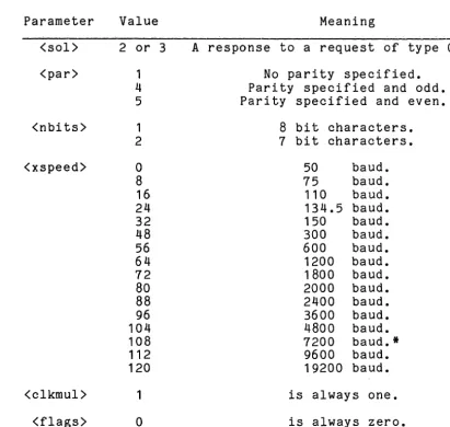
Description of Request-Terminal Parameters.... • .•••.
IIO Connector Pin Ass ignments •••••••••••••••.•••••.••••.
4-4 4-7
TH I S PAGE
INTENTIONALLY
CHAPTER 1
INTRODUCTION
The BitGraph terminal combines the reliability and cost effectiveness of raster-scan CRT technology with a high-performance microprocessor architecture to produce a low-cost advanced graphics terminal. The BitGraph terminal was developed by BBN Computer Corporation for multimode graphics applications, where multiple variable-sized character fonts and detailed graphical information are combined on the
display screen.
The BitGraph terminal stores graphical data as a direct bitmap in semiconductor memory, and its hardware
automatically retrieves such data for display refresh. All other operations on the bitmap data are performed by the MC68000 processor. This is one reason the BitGraph terminal
is more flexible and cost-effective in design than terminals that employ elaborate hardware to perform special functions that for many applications are neither useful nor necessary.
The BBN BitGraph terminal provides a high-resolution 1024-pixel by 768-1024-pixel display on a large, vertically mounted 9 inch by 12 inch black-and-white screen. It allows users to load a large number of fonts into the terminal and to select from them at will, and it provides a variety of character-oriented cursor-addressing and editing commands.
The BitGraph terminal supports graphical display
BitGraph User's Guide
are also provided to change a variety of modes and
parameters within the terminal, such as the baud rate, the nominal size of characters, the use of flow control, or the rendition of chara~ters and vectors on the screen.
CHAPTER 2
INSTALLATION AND USER MAINTENANCE
2.1 Site Considerations
In general, the BitGraph terminal, shown in Figure 2.1, can be placed anywhere that an electric typewriter might be placed. Care should be taken, however, to avoid extremes of temperature and humidity, such as from closed rooms without air-conditioning or constant exposure to direct sunlight. The terminal should not be placed in any location where it may get wet. Consult the data sheet specifications for more exact environmental considerations.
2.2 Unpacking and Installation
The BitGraph terminal shipping carton should contain the following items:
BitGraph User's Guide
To install the BitGraph terminal:
2-2
1. Remove the BitGraph terminal display unit from the shipping carton and place it in the desired work area.
2. Place the keyboard in front of the monitor and plug the keyboard interconnection cable into J4, located on the I/O connector panel at the rear of the unit. Screw the small strain relief screws on the connector into the I/O panel.
3. Verify that the on/off circuit breaker
switch, located at the rear of the unit, is in the off position. Insure that a 3-prong grounded power outlet is available.
5. Attach the host EIA cable so that the 25-pin connector mates with J6 on the I/O connector panel. Again, strain relief should be
provided by the small screws on the 25-pin connector. If communications protocol other than EIA RS-232-C is to be used, consult the Interface Information for description of the necessary cables and connector assignment. NOTE: if the host computer does not assert CTS and DCD (pins 5 and 8, respectively) pin 4 must be jumpered to pin 5, and pin 8 to pin
20.
6. Depress the power switch to provide power to the terminal. After approximately one
minute, you should see a banner at the top of the display, which contains a message
indicating what version of the terminal firmware you have. You should also see a blinking cursor below the banner.
7. Adjust the display intensity, if necessary, by turning the remote brightness control located near the on/off switch.
8. Refer to the Configuration Parameters section of Chapter 4 to change any of the terminal mode settings, such as baud rate, parity, etc. The terminal is now ready to use.
2.3 User Maintenance
The keyboard keys are the only moving parts of the BitGraph terminal; they require no preventive maintenance. All of the metal and plastic BitGraph terminal surfaces may be cleaned with a soft cloth, dampened with a mild soap and water. Cleaners with solvents should not be used, as they may damage the finish. For best display quality, the
51 tGraph User I' s Guide
-. • •. ~< ~.,." .. _A" ,~ ,". ,
CHAPTER 3
TUTORIAL
If any terms in this Guide are unfamiliar to you, please refer to the glossary at the end, following the Appendixes.
3.1 Overview: I/O and Character Interpretation
The BitGraph terminal is an intelligent terminal used for the graphical display of visual images. The BitGraph
terminal also supports a number of input or output devices, such as a typewriter-like keyboard, an interactive input device (mouse), and a hardcopy printer. It is normally connected to a computer system, called the "host," or to a telecommunications system used to access one or more host computers.
The host computer typically interacts with the BitGraph by sending and receiving 8-bit characters over the RS-232
communications link. The terminal may print characters that it receives directly on the screen, or it may interpret them according to the current "mode" of the terminal.
BitGraph User's Guide
the BitGraph terminal firmware translates them into specific font characters. The terminal then displays these characters in linear order along a horizontal line, moving the cursor to the next character position after displaying each character.
o The BitGraph terminal uses control characters to perform low-level actions such as communications link flow control. Control characters, which are nonprinting ASCII characters, are described fully in Section 4.3.
o The terminal uses control sequences to perform higher-level actions, such as loading a font, or drawing a line.
The BitGraph terminal acts upon the characters that it
receives in different ways, depending upon the current state of the terminal. These terminal states include its
emulation mode, the character set that it is using as the default font, and where the cursor is with respect to the limits of the screen.
3.2 Example: Drawing a Line
The BitGraph firmware acts upon commands to create graphic images. Some commands require little or no context to be acted upon. For example, a control sequence may draw a line or vector from the current position of the cursor to the display position indicated in the sequence. To draw a line from the upper left-hand corner of the screen (the "home" position) to the lower right-hand corner, place the cursor in the upper left corner by sending the Cursor Position command (CUP) with default arguments:
ESC [ H
The line is then drawn by sending the vector-draw command (BBNDRAW), with the coordinates of the lower right-hand corner:
ESC 768 1024 d
Recall that the spaces shown in the examples are NOT actually part of the command sequence and should not be
sent. Note that the above two sequences and all that follow in this tutorial may be transmitted from the host computer, or typed directly by the user on the keyboard, with the BitGraph in Local mode.
3.3 Character Sets and Fonts
Other actions, such as drawing a character, depend on the character set or font being used. The terminal may use the default font, or some other specified font. When the
terminal is initially powered up, the default font is the built-in font. When the BitGraph terminal receives a
printable ASCII character down the communications line, it prints that character in the default font at the current cursor position, and then moves the cursor to point to the next character location. The host computer may specify that a character be displayed in another font. In such a case, the terminal displays the character in the same position, but it may update the cursor to point to a different next-character location, depending on the width of the next-character just printed.
In general, the BitGraph firmware allows you to omit or default most parameters in a reasonable fashion. For example, if you specify that an ASCII character should be printed in a loaded font, without that font having actually been loaded, the firmware will display the character in the built-in default font.
3.4 Regions
A region is a rectangle on the display that has all the characteristics of the entire BitGraph display, but may not necessarily occupy the entire display. In other words, a region is a virtual display. Region 0, the default region, describes the characteristics of the whole display. Region
a
may not be modified by a region command.BitGraph User's Guide
toa smaller portion of the display. One region is always selected, and all commands to update the display refer only to the selected region of the display.. The Bi tGraph firmware does not support overlapping windows in the normal sense. While it is legal to define regions whose rectangles
overlap, the .Bi tGraph takes no notice of effects on
information that may have been displayed in regions other than the current one.
The primary function of a reg.ion is to restrict
modificattonsof the display to pixels within its borders. All character-, vector-, and point-drawing commands are clipped so that they only affect pixels within the current region •
4.1 Keyboard
CHAPTER 4
PROGRAMMING GUIDE
The BitGraph terminal is supplied with an 83-key detachable keyboard arranged as 65 keys in typewriter layout and an 18-key auxiliary keypad. In addition, the keyboard is equipped with an audible tone generator that supplies keyclick and bell indications, and 8 light emitting diode
(LED) indicators.
The actions of the nonalphanumeric keys are described below:
LOCAL
When the terminal is in LOCAL mode, characters typed on the keyboard are immediately interpreted by the terminal instead of being transmitted to the host computer. Characters
BitGraph User's Guide
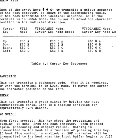
ARROW KEYS
Each of the arrow keys
+
f
~ ~ transmits a unique sequence to the host computer, as shown in the accompanying table. If the host transmits the identical sequence, or if theterminal is in LOCAL mode, the cursor is moved one character position in the indicated direction.
Cursor VT52 VT100/ANSI Mode, VT100/ANSI Mode, Key Mode Cursor Key Mode Reset Cursor Key Mode Set
Up ESC A ESC [ A ESC 0 A
Down ESC B ESC [ B ESC 0 B
Right ESC C ESC [ C ESC 0 C
Left ESC D ESC [ D ESC 0 D
Table 4.1 Cursor Key Sequences
BACKSPACE
This key transmits a backspace code. When it is received, or when the terminal is in LOCAL mode, it moves the cursor one character position to the left.
BREAK
This key transmits a break signal by holding the host communication serial line in a spacing condition for approximately 0.25 second.
NO SCROLL
When first pressed, this key stops the processing and display of data from the host computer. When pressed again, processing and display resume. Nothing is
transmitted to the host as a function of pressing this key. If host flow control is enabled, an XOF character will be transmitted to the host when the input buffer begins to fill if the host continues to transmit characters.
[image:21.623.72.523.143.679.2]RETURN
This key transmits a carriage return code. When it is received, or when the terminal is in LOCAL mode, it moves the cursor to the left margin.
LINE FEED
This key transmits a line feed code. When it is received, or when the terminal is in LOCAL mode, it moves the cursor one character position downward. If the cursor is on the bottom margin, a scroll up operation is performed. In
addition, if Line Feed Mode is set, the cursor will be moved to the left margin; see the Set Mode and Reset Mode
commands.
TAB
This key transmits a tab code. When it is received, or when the terminal is in LOCAL mode, it moves the cursor to the next tab stop to the right.
Numeric Keypad
The numeric keypad enables the user to enter numbers in a high-speed, calculator-like fashion. The numerals and the minus, comma, and period keys send the characters inscribed on them when they are typed. The ENTER key is equivalent to the RETURN key.
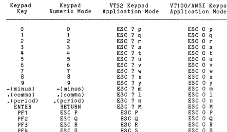
In addition, the terminal may be programmed to cause each of the keys on the keypad to send a uniquely identifiable
sequence of characters. Often, it is desirable to distinguish the keys on the auxiliary keypad from the
corresponding keys on the typewriter keyboard. To do this, place the auxiliary keypad in keypad application mode. In this mode, the keys on the keypad transmit unique sequences, given in the following table. Note that these codes are compatible with Digital Equipment Corporation's VT100 and VT52 terminals. The sequences to enter and exit
keypad application mode are given in the DEC VT52 Emulation section. The sequences to alter cursor key application and ANSI/VT52 mode are given in the ANSI section under the
BttGraph User's Guide
PF1 - PF4
Each of these keys transmits a uniquely identifiable sequence of characters. The sequence of characters will depend on which of the several keypad modes is selected.
Keypad Key
o
1 2 3 4 5 6 7 8 9 -(minus) ,(comma) • (period) ENTER PF1 PF2 PF3 PF4 Keypad Numeric Modeo
1 2 3 4 5 6 7 8 9 -(minus) ,( comma) .(period) RETURN ESC P ESC QESC R ESC S
VT52 Keypad Application Mode
ESC ? P ESC ? q ESC? r ESC ? s ESC ? t ESC ? u ESC ? v ESC ? w ESC ? x
ESC ? y ESC ? m ESC ? I
ESC ? n ESC? M
ESC P ESC Q
ESC R ESC S
Table 4.2 Keypad Modes
VT100/ANSI Keypad Application Mode
ESC 0 P ESC 0 q ESC 0 r ESC 0 s ESC 0 t ESC 0 u ESC 0 v ESC 0 w ESC 0 x
ESC 0 Y ESC 0 m ESC 0 I ESC 0 n ESC 0 M ESC 0 P ESC 0 Q
ESC 0 R ESC 0 S
The LED indicators are currently used to distinguish between the terminal being in On Linear Local mode. The third LED (L3) is used to indicate that the keyboard is locked, which happens when the host computer sends a flow control
character CXOF) telling the terminal to suspend input to the host. Usually this is shortly followed by another flow
[image:23.621.79.545.214.484.2]If the XON character never appears, the terminal must be reset, by entering Setup Mode, as described below. Although this is a rare situation, printing out a binary file may cause this effect, because an XOF character can be
inadvertently sent by the host.
4.2 Configuration Parameters
A number of configuration parameters can be changed by using terminal commands. The configuration may then be saved and will subsequently be restored upon application of power. Some of the parameters that can be reconfigured are the video sense (black on white or white on black), the baud rate of the host serial port, and automatic flow control with the host. The details of the user saving and restoring of configuration parameters are described here; performing these functions from the host by use of the BitGraph
Terminal Control Sequences is specified in Section 4.5 under Restore EAROM Context (BBNRECand Save EAROM Context(BBNSEC).
The SETUP key is used to toggle between being in and out of Setup Mode • When entering Setup Mode the top portion of the display is saved in a side buffer, and is used to display the user-settable parameters that may be set and saved. The original display contents are restored when the terminal exits Setup Mode. (Note: If a large number of fonts are downloaded or the user RAM is otherwise full, it is possible that the attempt to store the top of the user display will fail. This will result in a blank area at the top of the display when Setup Mode is exited.)
When in Setup Mode, the mode to be altered is highlighted. The user selects which mode to alter by using the up and down cursor keys to move to other modes in the window. When the cursor is at the top or bottom of the setup window, new modes will be scrolled onto the display as appropriate.
A mode is changed when the left or right cursor keys is pressed. The new mode is displayed. A newly selected mode is not immediately installed; it takes effect when the
BitGraphUser'sGuide
The following characters may be typed on the keyboard in Setup Mode with the specified meanings:
a
(zero): Total restart and reset of the terminal. Identical to power~cycle.P or p:Exit setup mode and print display. The current .contentsof the di splay are dumped as a bi tmapped image
to the line printer. (Assumes the Printer Option is installed, otherwise just exits.)
S: Save the current setup information in the EAROM.
R: Recall the setup information· in the EAROM.
Table 4.3 defines the default settings of the parameters and modes that are accessible in Setup Mode.
The following is an annotated list of the parameters and modes .that m~y be changed in Setup Mode, and subsequently saved under user control. The notation (Set) and (Reset) refers to the interpretation of binary parameters, which may be manipulated by the user in Setup Mode, or from the host computer program by Set/Reset Mode sequences. Refer to Table 4.3 for the default settings of these parameters.
LOCAL MODE: Values are "online (set)", and "local (reset)".
LOCAL ECHO: When in the Set state, the BitGraph terminal locally echos all keystrokes. When in the Reset state, no local echoing takes place. The initial default is Reset.
SCREEN: Set to "white (set)" for a white background and "black (reset)" for a black background.
WRAP: .Setto "on (set)" if characters printed at the right margin $hould wrap to the next line of the display. If set to "off (reset)" characters will stick at the right margin.
Default
Value Parameter
0, 0 Character and font used to draw the cursor.
1, 0 Character and font used to draw pointer cursor.
<CR> Tektronix EOT setting.
BG Emulation Mode. (BBNSEM)
18 Font assigned to GO character set. (SCS)
18 Font assigned to G1 character set. (SCS)
Reset
Reset
Set
o
Set when G1 character set 15 selected. (SO, SI)
Modes that are reset Initially. Line Feed Mode, Cursor Key Mode, Origin Mode, Keypad Application Mode. (SM, RM, Keypad Application Mode, Keypad Numeric Mode.) Local echo off. Initial default.
Modes that are set Initially. Screen Mode, Auto Wrap Mode, Flow Control Mode, Keycl Ick Mode, Last
Point Mode. (SM, RM) Local echo on.
Character graphic rendition. (SGR)
8 Tab stops, Initially every 8 col umns. (HTS, TBC)
RASTRPL
RASTRPL
9600
0, 0
768, 1024
Raster operation code for characte~s. (BBNSTO)
Poi nt and I I ne draw I ng RastOp code. (BBNSDO)
Host asynchronous port baudrate setting. (BBNSHB)
Margin X and Y settings, respectively.
Margin width and height settings, respectively.
BitGraph User's Guide
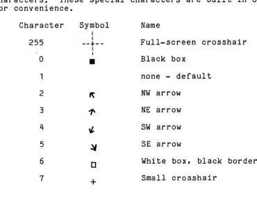
POINTER CHAR and POINTER FONT: A number of special
characters that are provided in the terminal firmware in font
a
can be used as either the pointer or standard text cursor character. The special characters are shown in Table 4~4~ below. The text cursor character always blinks, and the pointer cursor does not. The arrow characters are defined by the direction they point - NW is a diagonal arrow pointing towards the north-west corner of the screen, assuming that the top is north. The cursors are generally the opposite shading from the screen background. The shadings named in Table 4.4assume a white background; they automatically reverse on a black background screen.
4-8
Any character of any font can be used as the cursor characters. These special characters are built in only for convenience.
Character
255
a
1
2
3
4
5
6
7
Symbol
I
I
--+--I
I
•
+
Name
Full-screen crosshair
Black box
none - default
NW arrow
NE arrow
SW arrow
SE arrow
White box, black border
Small crosshair
[image:27.624.104.475.326.613.2]TERMINAL EMULATION MODE: Set to "bg", "vt52", "vt100" or "4010" to select the appropriate emulation.
DRAWING OP and TEXT OP: Sets the raster operation for drawing lines and text characters, respectively. Possible values are CLR, SAD, SAND, RPL, ERASE, Nap, XOR, DRAW, NSAND, SXND, COM, SOND, NS, NSOD, NSOND, and SET. See the discussion of Rastop for more information on the meaning of the various operations.
GO FONT and G1 FONT: Sets the GO and G1 font selection. A value of "18" selects the standard US ASCII font (font B). A value of "17" corresponds to the United Kingdom standard font (font A), which replaces the
"I"
character in the US ASCII font with the British pound sign.FLOW CONTROL: Values are "on (set)" and "off (reset)".
LAST DOT: Selecting "excluded (reset)" will cause the last point of all vectors to be omitted (useful when drawing vectors in complement mode). Selecting "included (set)" will include the last point.
ORIGIN MODE: Selecting "display (reset)" means that cursor positioning and reporting will be relative to the upper left corner of the display. If "margins (set)" is
selected, they will be relative to the margin settings.
RENDITION: Selects the character rendition, currently either "normal" or "reverse" video.
TABS: A marker appears on the tab line at the bottom of the Setup window at each place where a horizontal tab is set. A small cursor appears on the tab line when the primary cursor is over the TABS item, and is moved by use of the cursor keys. By hitting the TAB key on the keyboard, the user can toggle specific tab settings along the tab line.
LINE FEED: If "(LF> (reset)" is selected, the BitGraph terminal will perform an Index operation when it
BitGraph User's Guide
KEY CLICK: The values "on (set)" and "off (reset)"
respectively enable and disable an audible tone when keyboard keys are depressed.
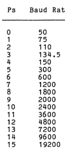
BAUD: Supported values are all the baud rates provided by the BitGraph terminal hardware, from 50 to 19200 baud.
PARITY: The sense of the parity code used over the host RS232 communications interface. Values are: "none", lleven", and llodd".
4010 EOT: The terminator for cursor coordinate data values sent from the terminal back to the host computer in Tektronix 4010 position reports. Normally a hardware strapping option on 4010s, default is <CR). Supported values are "(CR)ll, "none", and "<CR)<EOT)".
4.3 Control Characters
As mentioned in the Tutorial section, the host computer transmits three types of ASCII-coded characters to the
BitGraph terminal: standard ("printing") characters, control characters, and control sequences. Control characters have octal codes 000 through 037, and 177. Those control
characters that cause the BitGraph terminal to take some action are described in Table 4.5 below. Some control characters ignored on input are not placed in the input buffer (NUL) and so may be used as line padding characters. Others, such as DEL, are placed in the input buffer but not printed by the terminal firmware. DEL is a printing
character only in font O.
4-10
NOTE
Any control character cancels the
interpretation of a control sequence, if the sequence is not yet complete. Since unrecognized control codes cause no
fH tG ra ph User's G u ide Control Character NUL E:rX BEL BS HT LF VT CR us SO SI DCl DC3 ESC GS Octal Code 000 003 007 010 011 012 013 015 016 017 021 023 033 035 Action
Ignored on Input. Not stored In buffer. Responds with an ACK (006) character to the host.
Sounds the bel I.
Moves AP teft one character position. If AP Is at left margin, no action occurs.
AI so TAB. Moves AP to the next tab stop. In TEK 4010 mode, move one ch~racter space right.
Moves AP down one II nee I f the ANS I LFM mode Is set, also moves the horizontal position to the left margin.
In TEK 4010 mode, moves up one char. height.
..
Moves AP to left edge of display. Ends
Tektronix 4010 graphics output mode or GIN mode. Ends Tektronix 4010 graphics output mode or GIN mode.
SwItches to the Gl character set selected by a precedJng ANSI SCS sequence.
Switches to the GO character set selected by a preceding ANSI SCS sequence.
Also called XON, used to perform flow control i see Set Mode sequence.
Also known as XOF, for flow contr01. Introduces a termInal control seq~ence.
Enters TektronIx 4010 graphics mode.
4.4 ANSI Standard Sequences
This section consists of a definition of the standard ANSI control sequences supported by the BitGraph. As described in Chapter 2 of this manual, the BitGraph has many control commands that cause it to take action other than displaying a character on the display. Through these commands, the host can command the terminal to move the cursor, change modes, or take other special actions. Except as noted, all of the sequences described in this chapter are available for use at all times, regardless of the terminal emulation mode currently selected (see Select Terminal Emulation).
The sequences described in this section all conform to
American National Standard X3.4-1977. Refer to the Glossary for an explanation of the terms Ps and Pn as used in the parameter specifications.
CPR Cursor Position Report ESC [ Pn ; Pn R
The Cursor Position Report sequence is transmitted by the BitGraph terminal to the host. It reports the active
position by means of the parameters. The sequence has two parameters, the first specifying the vertical position and the second specifying the horizontal position. The default condition with no parameters present is equivalent to a cursor at home position.
This control sequence is solicited by the host sending a Device Status Report sequence with a parameter value of 6.
Note that the numbering of lines depends on the state of the Origin Mode; see the Set Mode and Reset Mode commands.
CUB Cursor Backward ESC [ Pn D
The Cursor Backward sequence moves the active position to the left. The distance moved is determined by the
BltGraph User's Guide
CUD Cursor Down ESC [ Pn B
The Cursor Down sequence moves the active position downward. The distance moved is determined by the parameter. If the parameter value is zero, one, or missing, the active
position is moved one position downward. If the parameter value is N, the active position is moved N positions
downward. If an attempt is made to move the active position beyond the bottom margin, the active position becomes the bottom margin.
CUF Cursor Forward ESC [ Pn C
The Cursor Forward sequence moves the active position to the right. The distance moved is determined by the parameter. If the parameter value is zero, one, or missing, the active position is moved one position to the right. If the
parameter value is N, the active position is moved N
positions to the right. If an attempt is made to move the active position beyond the right margin, the active position becomes the right margin.
CUP Cursor Position ESC [ Pn ; Pn H
The Cursor Position sequence moves the active position to that specified by the parameters. The first parameter specifies the vertical position, the second parameter the horizontal position. A parameter value of zero or one moves the active position to the first line or column in the
display, respectively. The default condition, with no parameters present, is equivalent to a cursor to home action.
The numbering of lines depends on the state of the Origin Mode. When the Origin Mode is reset, line numbering is
relative to the upper left corner of the display. When the Origin Mode is set, line numbering is relative to the upper left corner of the current margin settings, and the cursor cannot be positioned outside of the margins. See the
Set Mode and Reset Mode sequences.
CUU Cursor Up ESC [ Pn A
The Cursor Up sequence moves the active position upward. The distance moved is determined by the parameter. If the
parameter value is zero, one, or missing, the active position is moved one position upward. If the parameter value is N, the active position is moved N positions upward. If an attempt is made to move the active position beyond the top margin, the active position becomes the top margin.
DA DECID
Device Attributes Identify Terminal
ESC [ Pn c ESC Z
When sent from the host with a Pn of 0 or no parameter, this sequence solicits a DA response. The response parameters are a function of the current emulation mode setting in the BitGraph (see Select EmulationMode).
Emulation Mode Sequence Sent Notes:
Native ESC [ ? 50
.
,
<ver> <mem> <emu> c 1VT100 ESC [ ? 1
.
,
o
c 2VT52 ESC / Z 3
TEK 4010 ESC [ ? 50
.
,
<ver> <mem> <emu> c 1 ,4Notes:
1. The <ver> parameter reports the major (maj) and minor (min) software revision numbers of the BitGraph
terminal software as (maj
*
256 + min). For example, software revision 3.04 is transmitted as "772". The <mem> parameter is the number of bytes of free memory remaining in the terminal, divided by 1024. The <emu> is the current emulation mode setting (see SelectEmulation Mode).
2. These parameters correspond to a VT100 terminal with no options installed .( see VT100 User Guide, pg. 46).
3. These parameters correspond to a VT100 terminal
BitGraph User's Guide
4. This sequence is included even though TEK 4010s do not answer it.
DL Delete Line ESC [ Pn M
The Delete Line sequence deletes the specified number of lines from the display. The remaining lines below the deleted area, if any, then move up the number of lines
deleted. If no parameter is specified, one line is deleted. A parameter of zero or one deletes one line. The active position is unchanged.
DCH Delete Character ESC [ Pn P
The Delete Character sequence deletes the character at the active position and possibly other adjacent characters to the right according to the parameter. Characters to the right of the deleted characters are shifted left to the active position. The vacated character positions are cleared.
A parameter value of zero or one, or a missing parameter, deletes one character. A parameter value of N deletes N characters. The active position is unchanged.
DCS Device Control String ESC P
The Device Control String sequence initiates a mode in which an arbitrary string can be transmitted to the BitGraph
terminal~ A device control string is a string of graphic
and formatting characters starting with the first character after the Device Control String delimiter and terminating with a String Terminator sequence (ESC \).
In the BitGraph terminal, the Device Control Sequence introduces those commands that transmit a large bulk of data:
Download or Execute Load Font Character Display Pixel Data
The receipt of any nonformatting control character terminates the device control string, and is then
interpreted normally. The String Terminator sequence is interpreted as a no-operation by the BitGraph terminal. In addition, as the above commands all have some form of
inherent length information, they may self-terminate when they have received the proper amount of data.
DSR Device Status Report ESC [ Ps n
When transmitted to the BitGraph terminal by the host, the Device Status Report sequence with a parameter value of 5
solicits a Device Status Report response from the terminal. The status of the terminal is indicated by the parameter in the response, which is
a
for no malfunctions detected.If the Device Status Report sequence is transmitted to the BitGraph terminal with a parameter value of 6, the active position is reported to the host by a Cursor Position Report sequence.
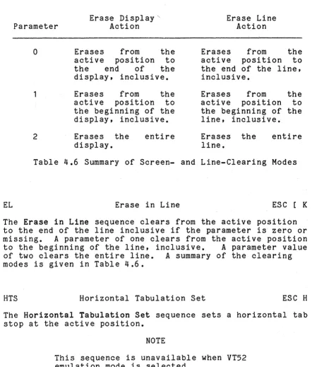
ED Erase in Display ESC [ Ps J
The Erase in Display sequence clears from the active position to the end of the display inclusive if the
BitGraph User's Guide
Parameter Erase Display" Action Erase Line Action
EL
a
1
2
Erases from the active position to the end of the dispLay, inclusive.
Erases from the active position to the beginning of the display, inclusive.
Erases the display.
entire
Erases from the active position to the end of the line, inclusive.
Erases from the active position to the beginning of the line, inclusive.
Erases the line.
entire
Table 4.6 Summary of Screen- and Line-Clearing Modes
Erase in Line ESC [ K
The Erase in Line sequence clears from the active position to the end of the line inclusive if the parameter is~ero or missing. A parameter of one clears from the active position to the beginning of the line, inclusive. A parameter value of two clears the entire line. A summary of the clearing modes is given in Table 4.6.
HTS Horizontal Tabulation Set ESC H
The Horizontal Tabulation Set sequence sets a horizontal tab stop at the active position.
NOTE
[image:37.613.63.505.119.638.2]HVP Horizontal and Vertical Position ESC [ f
The Horizontal and Vertical Position sequence is a synonym for the Cursor Position sequence.
ICH Insert Character ESC [ Pn @
The Insert Character sequence inserts erased character
positions at the active position according to the parameter. The characters at and to the right of the active position are shifted the specified number of character positions to the right. Characters that are shifted beyond the right margin are discarded.
A parameter value of zero or one, or a missing parameter, inserts one erased character position. A parameter value of N inserts N erased character positions. The active position is unchanged.
IL Insert Line ESC [ Pn L
The Insert Line sequence inserts erased lines at the active line according to the parameter. The lines at and below the active position are shifted the specified number of lines downward. Lines that are shifted beyond the bottom margin are discarded.
BitGraph User's Guide
IND Index ESC D
The Index sequence moves the active po.si tiondownward one line without changing the column position. If the active position is at the bottom margin, a scroll up operation is performed.
NEL
NOTE
This sequence is unavailable when VT52 emulation mode is selected.
Next Line ESC E
The Next Line sequence moves the active position downward one line and to the left margin. If the active position is at the bottom margin, a scroll up operation is performed.
RI Reverse Index ESC M
The Reverse Index sequence moves the active position upward one line without changing the column position. If the
active position is at the top margin, ascrall down operation is performed.
RIS Reset to Initial State ESC c
RM Reset Mode ESC [ Ps ; ••• ; Ps 1
Each parameter to the Reset Mode sequence causes a mode to be reset in the BitGraph terminal. A mode is considered reset until it is set by the corresponding Set Mode (SM) command. If the first character of the parameter string is a question mark? (octal code 77), the parameters are
interpreted as private modes. Table 4.7 describes the actions resulting from resetting a given mode.
SCS Select Character Set
The Select Character Set sequences are used to designate one of the possible terminal fonts as the GO or G1 character set. The sequence has a 2-character initiator that
determines whether the GO or G1 font is being reassigned, then a single terminator character that specifies which font is desired. The Shift In (SI) and Shift Out (SO) commands (see control character section, Table 4.1) are used to select the GO and G1 character set, respectively.
Subsequent text characters are displayed in the selected font.
The BitGraph terminal initially has three built-in fonts. Font B is the United States ASCII character set. Font A is the United Kingdom standard font. Font 0 is the VT100
special graphics font. The sequences to select these fonts are given in Table 4.7.
Additional fonts may be selected by first loading the font using the Load Font Character (BBNLFC) sequence and the Set Font Parameters (BBNSFP) sequence. You may load up to 79 distinct fonts into the BitGraph terminal at one time
~
,
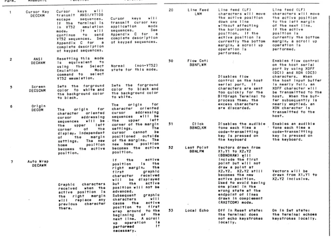
N N Private Parm. 2 6 7 Mode Mnemonic Cursor KeyDECCKM ANSI DECANM Screen DECSCNM Origin DECOM
Auto Wrap DECAWM
Reset Function Cursor keys will transmit ANSI/VT100 escape sequences. If the terminal Is In VT52 emulation mode, It will continue to send VT52 seq uences. See Appendix C for a complete description of keypad sequences. Resetting this mode Is equivalent to using the Select Emulation Mode command to select VT52 emumlatlon. Sets the forground color to white and the background color to black.
The origin for character oriented cursor addressing sequences wll I be the upper left corner of the dl spl ay, Independent of the margin settl ngs. The new home po~ltlon
becomes the active position.
Graphic characters received when the active position Is the right margin will replace any previous character there.
Set Function
Cursor keys wlll transmit cursor key application mode sequences. See Appendix C for a complete description of keypad sequences.
Normal (non-VT52) state for this mode. Sets the forground color to black and the background color to white.
The origin for character oriented cursor addressing sequences wll I be the upper left corner of the margin settings. The cursor cannot be positioned outside of the margins. The new home position becomes the active position.
If the active position Is the right margin. the first graphic character received w II I be d I sp I ayed but the active position wll I not be advanced.
Subsequent graphic characters wll I cause the active position to first wrap around to the beginning of the next I I ne. A scrol I up operation Is performed If necessary. Parm. 20 50 51 52 53 Mode Mnemonic Line Feed
LNM
Flow Cntl BBNFLWM
Click BBNCLKM
Last Point BBNLPM
Local Echo
Reset Function Line feed (LF) characters w II I move the active position down one II ne without affecting the horizontal pos I tl on. I f the active position Is currently the bottom margin, a scroll up operation Is performed.
Disables flow control on the host serial port. If characters are sent too quickly for the BltGraph Terminal to process them. the excess characters are discarded. Disables the audible tone each time a code-transmitting key Is pressed on the keyboard Vectors drawn from Xl. Y1 to X2. Y2 ( BBNDRAW) will Include the first point but wll I not draw a point at X2.Y2. X2.Y2 stll I
becomes the new active position. Used to avoid having one pixel In the wrong state at the endpoint of lines drawn In complement (RASTCOM) mode. Off In Reset state: the terminal does not echo keystrokes locally.
Table 4.7 Set (SM) and Reset (RM) Mode Actions
Set Function Line feed (LF) characters w II I move the active position to the left margin of the next line.
If the active position Is
currently the bottom margl n, a scroll up operation Is performed.
Enables flow control on the host serial port by using XOFF (DCl) and XON (DC3) characters. When the host Input buffer Is nearly full, an XOFF character wll I be transmitted to the host. When the buf-fer subsequently Is nearly emptied, an XON character Is transmitted to the host.
Enables an audible tone each time a code-transmitting key Is pressed on the keyboard.
Vectors wll I be drawn from XI.YI to X2.Y2 Inclusive.
On In Set state: the terminal echoes keystrokes locally.
[image:41.802.54.711.29.515.2]The Load Font Character (BBNLFC) and the Set Font Parameters (BBNSFP) sequences each use a number to specify the effected font. To calculate the value of the ASCII character used in the Select Character Set sequence that corresponds to the font number used in the BitGraph terminal private font sequences, add the value of the character '0' (32 decimal) to the font number. Similarly, to go from the
Select Character Set terminator to a font number, subtract the value of character '0'. Thus, the font numbers 0 through 15 correspond to the characters '0' through
'1'
(the ANSI private fonts), and 16 through 78 correspond to thecharacters
'@'
through'-I
(the ANSI standard fonts).Font characters that have not been loaded default to the standard US ASCII font; therefore all fonts initially appear to have all characters loaded. The characters default to the initial US ASCII font; not the potentially overloaded one.
SGR
GO Selection
ESC ( B ESC ( A ESC (
a
G1 Selection
ESC ) B ESC ) A ESC )
a
Meaning
Select US ASCII standard font. Select UK standard font.
Select US ASCII standard font.
Table 4.8 Select Character-Set (SCS) Sequences
Select Graphic Rendition ESC [ Ps ; ••• ; Ps m
The Select Graphic Rendition sequence invokes the graphic rendition selected by the parameter(s). All subsequent graphic characters are rendered according to the selected parameters. An empty parameter list is equivalent to selecting a zero parameter.
Currently, the only modes implemented are
a
(for attributes off) and 7 (for reverse video). In future versions,boldface (attribute 1), italics (attribute 3), and
BitGraph User's Guide
SM Set Mode ESC [ P s ; •.•• ; P s h
Each parameter to the Set Mode sequence causes a mode to be set in the BitGraph terminal. A mode is considered set until it is reset by the corresponding Reset Mode (RM)
command. If the first character of the parameter string is a question mark? (octal code 77), the parameters are
interpreted as private modes. Table 4.7 describes the actions resulting from setting a given mode.
ST String Terminator ESC \
The String Terminator sequence is used to terminate a Device Control String. If it is transmitted to the BitGraph
terminal when it is not in the process of interpreting a device control string, no operation occurs.
TBC Tabulation Clear ESC [ Ps g
The Tabulation Clear sequence is used to clear previously set horizontal tab stops. If the parameter is zero or missing, this sequence clears the tab stop at the active position. If the parameter is three, all horizontal tab stops are cleared.
4.5 BitGraph Native Mode
4.5.1 General Information
The sequences described in this section all conform to American National Standard X3.4-1977, in that they are either reserved for private use by that standard, or they begin wi th a private initiator. They are used to invoke those features in the BitGraph terminal that are not covered by the ANSI standard.
4.5.2 BitGraph Specification
BBNALN Screen Alignment ESC # 8
The Screen Alignment sequence fills the entire display with 'E' characters in the current font. Useful for screen
alignment and focusing.
BBNDAC Display All Characters ESC : Ps D
The Display All Characters sequence can help in debugging graphics programs by enabling you to see the characters actually sent by the host.
If the parameter is nonzero, the BitGraph terminal enters a mode in which printable characters are displayed as usual, but control characters are displayed in reverse video as the corresponding upper case letter. Control characters are not given their normal control interpretation. For instance, a reverse-video bracket [ represents escape. Each carriage return is displayed as a reverse video 'M', and also causes a combination of carriage returns and line feeds for
readability.
If the parameter is zero or missing, this mode is exited, and the terminal returns to normal; note that this is the only control sequence recognized in this mode.
BBNDRAW Draw Line ESC : <x> ; <y> d
The Draw Line sequence is used to draw a line from the active position to the specified <x> and <y> position. After drawing the line, the specified <x> and <y> position becomes the new active position.
BitGraph User's Guide
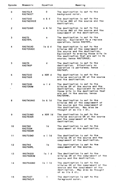
Lines may be drawn using any of the sixteen possible Rastop operation codes. When drawing lines, the Rastop operation codes are interpreted as if the source operand is a constant in the foreground color. Note that, with this
interpretation, the operation codes degenerate into four distinct cases:
1. drawing lines (RASTRPL, RASTDRAW, RASTSOND, RASTSET)
2. erasing lines (RASTCLR, RASTERASE, RASTNSAND, RASTNRPL)
3. complementing lines (RASTSAND, RASTXOR, RASTCOM, RASTNSOND)
4. no operation
Use the Set Drawing Operation command to change the line drawing mode.
To reduce the number of characters that must be transmited to the BitGraph to draw a vector, the TEKTRONIX vector
drawing sequence may be used; see Enter Graphics Mode (GSl.
BBNDOE Download or Execute ESC P : <op> <counthigh> ; <addrlow> ; <addrhigh> E
This sequence is used to perform a variety of functions concerned with downloading user 68000 software into the terminal.
An <op> parameter of 0 (zero) requests that the terminal accept and download Motorola Exerciser records. This is compatible with previous releases of the BitGraph Terminal software.
An <op> parameter of 1 (one) requests that the terminal accept and download packed pixel format data. The
<countlow> and <counthigh> parameters specify the low and high 16 bits of a 32-bit count of the number of bytes to download. The <addrlow> and <addrhigh> parameters specify the starting address of the memory to be downloaded.
CAUTION
The BBNDOE sequence always downloads an even number of bytes, and should always commence on an even byte. No
checksumming is performed with this downloading format; use it only over reliable serial lines.
An <op> parameter of 2 requests that the specified number of bytes of memory from the specified memory address be
transmitted back to the host in packed pixel data format. When this sequence is transmitted to the terminal, it first
transmits a preamble describing the length of the string to be returned, as follows:
ESC P : 2 ; <countlow> ; <counthigh> E
Here, <countlow> and <counthigh> are the low and the high 16 bits of the length of the string, repectively. This
sequence is followed by the contents of the string in packed data format (Appendix E). Finally, the BitGraph transmits a String Terminator sequence (ESC \).
An <op> parameter of 3 stores a string in the terminal, and an <op> parameter of 4 uploads a string in the terminal. Only the <count> parameter is needed to store the string; the terminal allocates space for the string on the heap. Similarly, neither the count nor the address parameter is required for opcode 4 (upload string). It simply transmits back the string previously saved by opcode 3.
When opcode 3 is used to store a string in the terminal, the BitGraph terminal first responds with a memory management report:
ESC : 0 ; <addrlow> ; <addrhigh> M
BitGraph User's Guide
After receiving the indication that the memory allocation was successful, the host transmits the contents of the string to the BitGraph two bytes at a time in the packed data format (Appendix E). Following the packed data bytes, the host should transmit a string terminator (ESC \).
The BitGraph terminal responds as for opcode 2 with the
string stored by the preceding store string sequence (opcode 3) when it receives the following retrieve string sequence:
ESC P : 4 E
The intent load map. you if an initially
is that opcodes 3 and 4 will be used to store The terminal can save and restore information address-independent sort of hook is used to find out where the information is located.
a for
BBNDPD Display Pixel Data ESC P : Ps ; Pn ; Pn s
The Display Pixel Data sequence enables the user to display facsimile or bitmap images by loading encoded pixel data directly into the display memory. It initiates a mode in which subsequent packed pixel data characters are accepted and written into the display.
The packed pixel data are considered to be the source operand to any of the 16 possible Rastop operation codes. The operation code is specified as the first parameter.
The second parameter specifies the width of the rectangular region of the display to be filled in, and the third
parameter specifies the height. Filling begins at the active position and proceeds left to right, then top to bottom. At the completion of the command, the active position is unchanged.
The format of packed pixel data is described in Appendix C. The command terminates when when any nonspacing control character is received. To conform with ANSI standards, the String Terminator sequence (ESC \) should be sent.
Note that ESC P is the ANSI standard Device-Control String sequence.
BBNFILL Fill Rectangle ESC <xdest> <width> <char>
<opcode> <ydest> <height> ; <font> f
The Fill Rectangle sequence is a specialized version of Rastop that is used to fill a rectangular region of the display with an arbitrary stipple pattern. The <opcode> parameter specifies one of the 16 possible Rastop operation codes as the operation to be used when filling the
rectangle. The <xdest> and <ydest> parameters specify the lower left corner of the rectangle to be filled. The
<width> and <height> parameters give the size of the rectangle, which is clipped to stay within the current clipping region.
The stipple is an arbitrary sized pattern taken from the specified <char> in the specified <font>; the character must first be loaded with the stipple pattern using the
Load Font Character command.
If the <font> parameter is omitted it will default to the last font used in a Fill Rectangle sequence, to save the transmission time of the extra characters. A Fill Rectangle sequence with a
a
<width> or <height> can be used to set the initial fill font without altering the display.The stipple pattern is automatically aligned to an even
multiple of the width and height of the specified character. The adjustment insures that the stipple pattern will be
properly aligned when two rectangles drawn with the same stipple pattern are abutted.
BBNLFC Load Font Character ESC P <op> ; <char> ; <font> <rwidth> <rheight> <xadjust> <yadjust> <xupdate> <yupdate>; <x> <y> L
There are two major commands for manipulating fonts.
BitGraph Userts Guide
If the <op> parameter is 0, load a new raster pattern for a font character. It initiates a mode in which subsequent packed pixel data characters are accepted and stored in the specified font character. The format of packed pixel data is described in Appendix C. The <char> parameter is the character to be changed; it must be in the range of
a
to 255(decimal). The <font> parameter is as specified under Select Character Set ; it must be in the range of
a
to 78. Subsequent parameters, if unspecified, acquire their values from the font defaults. The font defaults, if not set, acquire their values from the initial US ASCII font.Note that the BitGraph terminal can directly display only the 96 characters with ASCII values of 32 through 127 in each font. The expanded range is made available to provide a convenient area for the storage of cursors or stipple patterns that may be associated with the font.
The <rwidth> parameter specifies the width of the raster image of the character in pixels. If the <rwidth> parameter is specified but <xupdate> is NOT specified, <xupdate>
defaults to <rwidth>.
The <rheight> parameter specifies the height of the raster image of the character in pixels.
The <xadjust> parameter specifies the number of pixels to the left of the cursor to draw the lower left of the raster image of the character.
The <yadjust> parameter specifies that the number of pixels below the cursor to draw the lower left of the raster image of the character.
The <xupdate> parameter specifies the number of pixels to add to the X position of the cursor after drawing the character. If the <rwidth> parameter is specified but
<xupdate> is NOT specified, <xupdate> defaults to <rwidth>.
The <yupdate> parameter specifies the number of pixels to add to the Y position of the cursor after drawing the character.
Filling begins at the upper left corner of the character and proceeds left to right, then top to bottom. One bits
represent the foreground color; zeros represent the background color. The command terminates when any
nonspacing control character is received. To conform with ANSI standards, the String Terminator sequence (ESC \) should be sent.
If the <op> parameter is 1, copy a rectangle from the display into a font character. The parameters are as for Opcode 0, with the additional <x> and <y> parameters being used to specify the location on the display of the lower left hand corner of the rectangle to copy into the font character.
The BitGraph terminal stores fonts in one of two formats. The first format is more compact, but also more restrictive than the second format. Characters of both types may be intermixed in one font to minimize storage consumption. The first format is used if the width of the font character is less than 128 (or it is defaulted) and all subsequent
parameters are defaulted. The overhead for this representation is 2 bytes per character.
In the second representation, all parameters are stored as 16-bit signed quantities. The overhead for this
representation is 14 bytes per character.
For each font there is additional overhead associated with the range of characters that have been loaded, where the range is the difference between the indices of the highest and lowest character loaded. The overhead is 4 bytes for each character in the range.
BBNMEM Memory Management ESC: <op> ; <10w16> ; <high16> M
This control sequence allocates and loads user RAM in the terminal. In this sequence, the <10w16> and <high16>
parameters respectively form the least and most significant 16 bits of a 32-bit number. The firmware treats the
resulting 32-bit number either as a byte count or as an address, depending on the <op> parameter.
If the <op> parameter is zero the following parameters are treated as a byte count. The sequence solicits a Memory Management report of the form:
BitGraph User's Gu