A GUIDE TO ASSEMBLY
LANGUAGE PROGRAMMING
FOR THE UNIVAC 1108
by
R. J. Ciecka and G. R. Ryan
UNIVERSITY OF MARYLAND
COMPUTER SCIENCE CENTER
A GUI
DE
TOASSH1BL
YLANGUAGE PROGRAMMING
FOR THEUNIVAC
1108by
R. J. Ciecka
and G. R. RyanSEPTEt~BER 1971
OFFICE OF USER SERVICES COMPUTER SCIENCE CENTER UNIVERSITY OF
MARYU\ND
INTRODUCTION
This manual, originally prepared by R.
J.
Ciecka and G. R. Ryan
and presented through the Department of Electrical Engineering of the
University of Maryland on March
1,
1971, is herewith issued by the
Computer Science Center of the University of Maryland under the reference
number
CN-2.The departmental identification assigned by Electrical
Engi neering is
100100,
\I/hi ch rep1 aces that department
Is manual
!OO1
OC.
References used in the preparation of this guide include:
UP-4053; UP-4040; UP-4042; and the University of Maryland User Reference
70-01.
.
The following is the ortgina1 introduction to the manual:
This man'ua1 provides a concise and relatively complete guide to
the UNIVAC 1108 Assembler. It is designed. primarily for the student who
is having his first contact with 1108 assembly language, but will also
serve asa handy reference for the more advanced programmer.
Information
from as many sources as could be found had been combined and condensed so
that for the first time (to our knowledge) the user can find information
on assembly language subroutine linkage, input/output, and diagnostic
processors presented in a clear manner. Those users who find that they
need still more detailed information should consult the UNIVAC and U of M
references 1 isted at the beginning of this manual.
.
-It
is'
a pleasure
to·
acknowledge the many and varied contributions
of the University of Maryland's Computer Science Center Systems Staff.
In particular we would like to thank Ray Cook of the Systems Staff and
Professor Marshall D.
J~bramsof the Oepartment of Electrical Engineering.
TABLE OF CONT,ENTS
1. Calling the As sembler ':" ." ... .. ..
-Page 1 2. Basic Assembler Language _ .. -2. 1 Computer Instruction - Word Format - - - ~ 2.2 Assembler Format .. ..; .:. 2.3 Description of Fields -1 1 2 3
3.
2. 3. 1 Label Field -2. 3. 1. 1 Labels .:. -2.3. 1.2 Location Counter Declaration -2.3. 1.3 Location Counter Reference .. -2.3.2 Operand Field - - - .. - - - - ~ -2.3.2.1 Function Code Designator, f -2.3.2.2 Operand Qualifi~r or Minor Function Code Designator, j --2.3.2.3 The Register Designator Field, a -2.3.2.3a A-Register Designator, A(a) - - - -'- - - - 2.3.2.3b XRegister Designator, X(a) -2.3.2.3c R-Register Designator, R(a) , - - - .. -, - - - --2.3.2.4 Definitions of Registers in Assembler Programs - - - 2.3.2.5 Index Register Designator, x 2.3.2.5a Index Register Incrementation Designator, h .:. 2.3.2.6 Operand Address or Operand Designator, u -2.3.2.6a Indirect Addressing Designator, i _ .. - - - -:- - -":'2.4 Continuation .. .. .. -3 3 3 4 4 4 5 5 5 6 6
6
6 7 7 7 8 8 2. 5 Te rmination - - - ,- - - .. - - - .. '- - .. ,- - ~ .. .. .. -2.6 Ejection of Paper - - .. - .. - .. - .... - - - .. - .... '- - - ... - - - 82.7 Data Word Generation - - - _ .. - - - _ .. - - .. - - - -- 8
2. 7. 1 Expre s sions - - - .... - - -
9
2.7. 1. 1 Elementary Items - - - .... .;: - - .. - - - 9
2. 7. 1.2 . Octal Values - - - ... - - - 9
2.7.1.3 Decimal Values - - - ~ -2. 7. 1. 4 Alphabetic Items , .... .:. .. -2. 7. 1. 5 Floating Point and Double Precision .. ' .. Subroutine Linkage ,, .. • -3.1 Calling Sequence .. -3.1. 1 Abnormal Return - - - .. - - - .. - - - .. - - .. 3.1.2 3.1.3 Function Value Return .... - - .. - - - .. - - - .. - - - - .... Normal Return - - - .:. - - - .. - - - .: -- - - -
~
.:. -99
10 10 10 11 11 11 3.2 Use .of Registers by Subroutine' - - .. ,- - - -: .. - - -.-' - - - - -. - 123. 3 The Walk-Back-Packet - - - .. - - - ""...; .. - - - - 12
4. Termination of Execution - - - .. - - - .. - - - 12
5. Assembler Directives - - - .. - - - - .... - - ;;, - - - 12
5.1 The Reserve Directive, RES - - - - -rOO - - - - - . . - - . . - - - " ; ' - - - 12
5.2 The END Directive, END - - - .:. - - .. :. - - - .. - - - 13
5.3 The Equate Directive, EQU - - - .. - .. - - - .. - - - 13
[image:4.612.67.571.49.749.2]5. 5 The FORM Directive, FORM ... - .. _ ... - - - - .. - - - -, ' 14
6. Input/Output - - - .. - .. - .... - '- - ... - - - J 4 6.1 The Format Sepcification ... - - - - -'-: - - - -' - -, - - -,- - - .. 14
6.2 Assembler Output - - - ... - - - 14
6.2. 1 Line Printer Output - - .. , - - - .. - - - -- -- - - 14
6. 2. 2 Output To Othe r Device s - - - .... - 1 5 6.3 Assembler Input - - _ .. - - - .. - - - 15
6. 3. 1 Reade r Input .. - - - .. - .... - - - - -' - - - - ~ - .: - .. - .. - - - 15
6. 3.2 Input With END Clause - - - .. - - - 16
6.4 Performing the Input/Output- - - .. - - - .. - - - 16
7. Simple Assembly Procedures - - - -'- - - 16
7. 1 The Func tioning of Proc edure s - - -' - - - 16
7.2 C re ating a Procedure - - - 17
7. 3 Declaring a Procedure - - - ..: - - .; - - - .. - - - - 18
7.4 Using a Procedure - - - .. - - - 18
8. The Assembler Code Listing - - - :.. - - - .:. - - - - 19
9. Diagnostic Processors - - - .. - - - 20
9. 1 Obtaining a Snapshot Dump Via X$DUMP - - - :.. - - - - 20
9.2 Obtaining a Snapshot Dump Via SNAP$ - - - 21
9 .. 3 Obtaining a Post Mortem Dump - - - - -- - - - .. -, - - - - .. - - - 22
9.4 Obtaining Dumps Via PDUMP - - - -, - - - -- - - 23
10. Glos sary and Conventions - - - .. - - - 24
'Appendix A -C ode/Symbol Relationships - - - 27
Appendix B-Instruction Repertoire - - - 28
'I'able B-1 - - - .. - - - .... - - - 28
Table B-2 - - - .. - - .. - - - .. - - .. - - - .. - .. - - - 37
Table B-3 - - - .. ,.. - - - '. - - - ~ • ... ~ - ~ - - - - 38
Appendix C -Assembler 'Error
Flap
and Messages - - - -.: - - - 39Appendix D-AssemblyLiBting Decoding Reference - - - 42
[image:5.612.73.556.51.491.2]1. Calling the Assembler
Under EXEC 8 the format of the aseembly control card is:
@ASM, <option:s> <field 1>, <field 2>, <field 3>
The available options are coded as follows:
C Produce symbolic listing (no octal).
D Produce double -spaced l~,Stillg.
M Request 10K additiona.l core for symbol and procedure sample table. N Suppress all listing.
o
Produce octal listing only (no symbolic).S Produce octal and symbolic l,isting (Normal listing option).
T Request 5K additional core for symbol and procedure sample table. U Update and produce new cycle of source element.
I Insert new element to program file ,from control system.
W List corrections.
< field 1> is the input source file and element. < field 2>
is
the relocatable file and element. <field 3> is the updated source file and element.If the I option is on (as when inserting from cards), specification <field 1>
names the program file to contain the source code. If a'Ssembling from tape,
<field 1> is the file name of that tape, <field 2> is the relocatable program element name, and <field 3> specifies the name of the program file to
con-tain the source code. If file name s are not specified, the temporary run file
is utilized. If assembling fr01TI tape and the tape is positioned incorrectly
(to an element other than the one specified) an error is produced.
2. Basic Assembler Language
2.1 Computer Instruction-Word Format
Every machine instruction for the 1108 adheres to the following format:
-Where:
f specifies
j specifies
a specifies
x specifie s
h specifies
i specifies
u specifies
.2 •.
j
26
the function code.
the partial word designator or minor func tion code, if any.
the control register or input/output c:h.:..nnel, if any. the index regbtel', if any.
index Illodification and if set calls for addre s s luodification" indirect addre s sing.
the address field.
2.2 Assembler Format
In writing instructions using the 1108 Asscnlbler langu::tgc, the progralumer is primarily concerned with three Helds: a label field, an operation field, and an operand field. It is possible to relate the sYIllbolic coding to its
associated flowchart, if desired, by appending comments to each instruction
line or program segment.
All of the fields and subfields .following the label field in the 1108 Asselubler are'in free forIll providing the greatest convenience pos sible for the pro-graIllmer. Consequently, the programmer is not hampered by the necessity
to consider fixed form boundaries in the design of his symbolic coding. It
is highly recommended that within the confines of a giYen program, the pro .. gramluer keep a fixe'd set of colurnn convel1tions for th(~ bake of legibility.
The basic line of coding is divided into 3 or fewer fields, called label, opcl'a-tion, and operand fields. A field is terIllinated by one or more spaces and
Illay be divided into subfields. A subfield is an expres~ion which is terminated
by a comma followed by zero or more spaces. The last subfield h1 the field, of course, is terminated by the space (at least one) that tc!rminates the field,
The format of a symbolic instruction differs from the computer instruction word for convenience of programlning as follows. COnllUal:> separate subfields.
LABEL OP OPERAND
FIELD FIELD FIELD
F A, U,X, J
In addition to instructions of the type discussed above, there are several which do not u::e the A fiel d. The operands of such instructions comprise the U, X, and J subfields.
LABEL
2. 3 Description ofF ie Ids
2. 3. 1 Label Field
OP
F F, J
OPERAND
U,X, J
U,X
The label field, where used, must "tart in column one and te rminate ·with a blank. It may contain a .declaration of a s:pecific location counter or a label or both, as explained below.
2. 3. 1. 1 Labels
A label is
a
means of identifying a value or a line of symbolic coding. It con-sists of an alphabetic character which may be followed by as many as elevenalphanumeric characters (A throu'~h Z and 0 through 9). When a label is used,
it must begin in column one and terminates with a blank.
In addition to the alphanumeric characters, the.
$
may be used in a labelbeginning with the second character. However, the use of the
$
is limitedbecause references to the Executive System are made via system's labels which utilize the
$
in various cl1aracter positions (see "1108 Executive System,ProgrCl.mmer's Reference Manual", UP-4144).
An external label is a label the value of which is known outside the program. Such labels are suffixed with an asterisk (e. g. GOT>:<). Th~ asterisk does not count as a character of the label. Any label which is assigned a single pre-cision value including locations of double prepre-cision constants may be made external. They arc as signed the relative addres s of the fir st word of the value generated.
2.3.1.2 Location Counter Declaration
There are 32 location counters in the 1108 Asr:cmbler, anyone of which may
be used or referenced in any sequcnce. These counters provide information
required by the collector to regroup lines of coding in any specified manner. This regrouping capability enable s isolation of constants or instructions, or components of each which in turn gives great flexibility to segmentation. A specific location counter is declared by writing $(e) as the first entry in the
label field, e being the location countc r numher (0 through 31). Any change
-4-specified location counter remains in u~e until a new location couriter is
declared. If no location counter is explicitly :=;pecified, the program is
con-tro1led by location counter zero, Any 1hne a lncation 'cml11ter is specified. all ,subsequent codingfaUs under its control. To include a label on the same line as a change -of -location-counter item. one must place a comma between the closing paren and the label. with no imbedded blanks (c. g .• $(2). LABEL).
Each -new location counter entry hegi.ns the coding relative to zero. Coding rc surned under a connte r that has been ul'ied previously continues at the last address specified for that countcr.
2.3.1. 3 Location Counter Referencc
Reflexive addressing may be achie'V('d by referencing the current location
counter, or a specific location counter. '\vithin a symbolic line. The symbol
for a current location counter refc-'C'nce j!';
$.
When the asscrrlbler encounters$
it inserts the value of the contro:lling location counter. A referenc~ to a specific location counter is made by $(e). where e denotes the specified loca-tion counter. In this case the assembler substitutes the value of localoca-tion counter e for the symbolic reference. Whf'n $+b is coded care should be taken so that the source-cod"d int(~rval b does not extend Over a procedure call. This is particularly a problem if the procedure called may generate a variable number of lines of code.!tis standard programming practice to assemble the instructions under odd location counters and the data under e'Ven location counters.
2. 3.2 Operand Field
The operand field starts with th(' fir 5t non-blank character following the label
field. The components of the operand field arc .called subfields and repre sent
the information necessary to complete the type of line determined by the
opera-tion field. Subfields are separated by commas. A comma may be followed by
one or more blanks •
. Most operands may contain feVicr than the maximum lll1mber of subfields implied by the operation field. If a subfield other than the normal fir st or last is to be ornitted. two continguous COlumas should be ul'!ed to denote that subfield (e. g ••
,,). 1£ the last~subfield or subfieldR are to be omitted, no comma may appear
immediately following the last coded subfidd. A period l'ipace coded just after this subfield stops scanning c111d :::pceds np aRsembly time (e. g., .15).
~. 3.2.1 Function Code DCRignator, f
The machine language function code, or f designator, contained in the leftmost
5 .
-
-2.3.2.2 Operand pualifier or Minor Function Code D<.:,.signator, j..;,..
When f< 708' the j designator determines whether an, entire ~perand, or only
a part of it is to be transferred to or from. the arithlnetic section. As previously rrlentioned, in instructions where £> 70. j serves as a minor function code rather than as an operand qualifier. When £=70, the j-designator combines with f to form the function code, and may not be coded.
As an operand qualifie r in the case of partial word transfers to the arithmetic
section, j specifics which half.-word, third-word. or sixth-word is to be
utilized. The transfer is always to the low order positions of the arithmetic
section. In transfer s from the arithrnetic section~ j spedfie s into which
half-word, third-word or sixth-word the low order positions of the word in the arithmetic section will be transferred.
In half-word transfers to the arithmetic section, j can specify whether sign
extension is to take place. If it is specified by coding j as 3 or 4, the rnost significant bit of the half-word fills positions 35 thru 18 of the control register.
If sign extension is not specified, i. e .• j is coded as 1 or 2, positions 35 through 18 are zero filled.
Sign extension always occurs for third-words a.nd never occurs for sixth·.words. No sign extension occurs for tranfifers from the control registers.
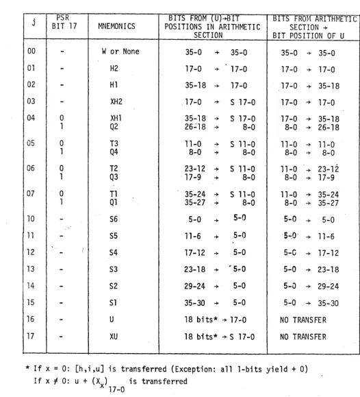
The mnemonic letter codes used in asselnbly language corresponding to. the numerical j designators are given be'low.
When j equals 16 or 17, the u-field of the inst'ruction becomes the effective
operand rather than the address of the operand. When j is coded as 17, sign
extension is effective.
J-designators are totally ignored when "U" is a control register, except for 016 &: 017, which behave normally.
2.3.2.3 The Register Design~tor Field, a
The entry in the A subfield represents the absolute control store address of an arithmetic, index, or R register as required by the instruction.
I , / '
2.3.2.3a A-Register Designator, A(a)
The a-designator normally specifies a c.ontrol register location. For arith~.
-6-2.3.2.3b X-Register Designator, X(a)
The a-designator is also used to reference anyone of 15 index rcgisterf; in control memory. An X-Register is iD1plied by the function code in certain instructions. Control register 000000 cannot be normally referencf'd by an a -designator.
2.3.2.3c R-Register Designator, R(a)
The a-designator is used to reference anyone of 16 R-registers. An
H.-register is implied by the function code in certain instructions.
Note: Any time a repeat count instruction is executed (such as BT. and all
search instructions) the repeat count must be in Rl. Univac docurnentation
doe s not mention this!
2.3.2.4 Definition of Registers In Assembler Programs
A procedure in the library is available which wtL:n called by
AXR$
will define symbols for the useable user registe)' set as follows:
Ai. i=0.1 . . . . ,15 Xi, i=l, 2, •.. ,11 Ri, i=l. 2, . . . ,15
are defined for accumulators. are defined for index registers. are defined for R -registers.
The accumulators AO through A3 Inay also be us-ed as index registers,
corresponding to X12, X13, XI4, XIS respectively. Also the j subfield of an
instruction is defined by the AXR $; procedure as follows:
HI and H2 refers to HI
XHI and XH2 refers to HI
HZ
, sign extensionTI, T2, T3 refers to Tl T2 T3
Ql,Q2,Q3,Q4 refers to Ql 02 Q3 Q4
(Note: quarter-word references may only be used in special circumstances)
81,82,83,84.55,56
u
xu
w
refers to 151
I
52I
53I
84I
55I
561refers to immediate operand
refers to irnmedjate operand, sign extension
refers to whole word operand
2.3.2.5 Index Register Designator, x
The format of the indexing infornlCition stored at the control register address
specified by the x-designator is s110wn oelow-. Bits 17-00 (X ) contain the
-7-increment which may, if desired, be used to change the value of X M . This
increment may be positive or negative.
18 17
2.3.2. Sa Index Register Incrementation Designator, ~
When the h-desi.gnator is coded as 1, the value of X M in index register X is increased by the value of XI' This incrementation takes place during the instruction; after the addition of u and the index register. in fonning the effective address. When h is 0, no incrcmentation !a.kes place.
The entry in the X subfield repre sents the specific index register to be used. Index register incrementation is indicated in assernbly language by means of an asterisk preceding the X subfield (e. g. ~:'X). The 1108 is a one I s
comple-ment machine and doe s pre -indexing. This means it increcomple-ments fir st and then performs the re st of the instruction.
2.3.2.6 Opera~d Address or Operand DesiGnato~, u
For all instructions the u field specifie s an operand for the particular instruction involved. For every instruction cycle the "effective u" must
fi "st be calculated. If no addres s modification, then the coded u field is the . effective u. If address modification is specified (~y an entry in the X field)
then the right half of the specified index register is added to the coded "u" and
the result becomes the effective u. For the case of indirection, see the
section below.
2.3.2.6a Indirect Addressing Designator, i
The i-designator specifies either direct or i:pdirect addressing of the operand. If i is code~ as 0, direct addressing is specified, and u is the effective
add-ress of the operand. If i is coded as 1, indirect addressing is specified. Bits
21-00 of the u-addressed operand replace bits 21-00 in,the current instruction. Since the 22 bits include the x, h, i, and u-designators, all indexing, index register incrementation, and indirect addressing operations can be cascaded
until the i-de;ignator in one of the temporarily forrned instructions is O. If
j< 16, normal partial-word operations on the contents of the addre s s specified by u are pe riorm.ed at the end of cascading. If j= 16 or 17, cascading is halted when either the i-de signator or the x-de signator, or both, become
zero; the value in u 17 -00 become s the actual operand. Thus, for j=16 or 17.
indirect addressing is not only conditioned by the i-designator, but is also con-ditioned upon the x-designator being a non-zero value.
The entry in the U subfield represents the operand base address. Indirect addressing is indicated by means of an asterisk preceding the U subfield
-8- .
2.4 Continuation
If a semicolon (j) is encountered outside of an alphabetic item, the current line
is continued with the first non-blank character on the following line. Any char-acters on the line after the ; are not considered pertinent to the prograrn
assen1bly, and are transferred to the output listing ~f, comments. A semicolon
should not be used within a comment unless it is des .. red to continue that com-ment on the nf'xt line.
immediably follow the blankR.
2. 5 Termination
If a line is broken within a sub-field, the semicolon must last character of the previous line, with no intervening
A period followed by a blank (. ) terminates a lir>e of coding except when it occurs inside an alphabetic item. Any additional subfields implied by the oper-ation field are t2ken to be zero. The space fo'1Ji'vitng the period avoids con-fusion with the notation for floating point num!;.€rs which use the period without a space. A continuation or termination Inark ::nay occur anywhere on a line except as noted above. Following the iniorrnation portion of a line, any
char-acters may be entered as comments except the apostrophe (I ).
2.6 Ejection of Paper
A slash (/) appearing in column one advances paper in the printer to the top of the next page. This same line may also contain a line of coding with the label field starting in column two. If it is desired to use the remainder of the line as a comment, a period must follow the slash.
2.7 Data Word Generation
A
+
or - in the operation field, followed by one to six subfields generates aconstant word. The
+
or sign may be separated from the subficlds by anynumber of blanks. If the
+
sign is omitted, a positive value is assumed.Subfields are separated by commas, which may be followed by one or more blanks.
If the operand field contains one subfield, the value of the subfield is right-justified in a signed 36 -bit word unle ss the value is double precision in which case it is right-justified in tv..o 36-bit words. If the operand field contains two subfields,. a data word containing two I8-bit subfields is created; the value of each subfield is right-justified in its respective field. Similarly three sub-fields generate three 12-bit sub-fields and six subsub-fields generate six 6-bit sub-fields.
Each subfield in the operand field may be signed independently (i. e.,
comple-mented if the subfield is preceded by a -).
If the operand field contains one subfield immediately followed by a D or a
-9-2.7.1 f~):..2re5sions
An expression is an elen1entary iten1. or a Eedes of elerne:,tary items connected by operators. Blanks are not p(~rmitted wiUlin dn eXjn-,:cbslon.· The combination of single and double precision values generillly .re8U~, :,n if double precision value.
2.7.1.1 Elen'cnta TV Items
An elen-u:ntary item is the sITlaHest elenlCnt of ;:..'.B1kr!.,j)ler cude that can stand alone; an elenlCntary itcm doe s not contain an ()P'~ l e t :i"' ..
2.7.1.2 Octal Vahlcs
An acta] value n1ay be an elenleutary iteln. S U t : ; J l itern is a grmJP of octal integers preceded by a zero. The assemb]t.~l' (;0-;:,,\ lCS a birvny (.·quivalent of
the itel1.1f s val'ue riglJt-justified in a sig11ecl u,~ f.f·tlle: sigrl IS ~~)Jxlitted,~ fh.e
value is assun1ed to be positive.
For example,
+
017 -074 -021PRODUCES OC 'fA L WORD 000000000017
PRODUCES OCTAL wc~rlD 7717777T1703
PRODUCES CC TAL WORD 777777777756
A double precision octal val'.le is produced by writing a constant lar ger than
36 bits or by placing a letter D immediately after the last octal digit.
2.7.1.3 Decimal Values
A decimal value may appear as an elementary item. within an expression • . A decimal item is a group of decimal integcrs!l9! preceded by a zero. Such a decimal valuc, is represented by a right-justified and Edgned binary equivalent within the object field. If the sign is omitted, the valu(! is assum.ed to be
positi ve.
For example,
+
12+2048 ,-04162
PRODUCES OCTAL WOH.D OO"()Q00000014 PRODUr::ES OC TAL WORD 000000004000 PRODUCES OCTAL WORD 777777767675
A double prccision decimal value is produced b)' writing a value larger than 36 bits or by placing the letter D immediately following the last decimal digit.
2. 7. 1.4 A lphabetic Items
-10-appears left-justified within its field. 1£ there are less than six characters, the alphabetic item is followed by Fi.eldata blanks (05 for each blank).
If an alphabetic item is preceded by a plus or minus sign, it may contain a
maximum of 12 characters. A positive signed value ;: r:-~)ears right-justified
within its field with the remaining field filled in with ze:!"os. A minus sign preceding the value produces the complement of the value and appears left-justified in the field. If the nUluber of characters is less than seven, only one computer word is used. An alphabetic item used as a literal is assumed to be preceded by a plus sign. A D immediately follo·wing the right apostrophe forces double precision.
'HEAD'
+
'HEAD', HEAD7890' + 1 HEAD7890 1 +'HEAD'D
PRODUCES OCTAL LEFT-JUSTIFIED 151206110505
PRODUCES OCTAL RIGHT-JUSTIFIED 000015120611
PRODUCES 151206116770 716005050505
PRODUC ES 000000001512 061167707160
PRODUCES 000000000000 000015120611
2.7. 1. 5 Floating Point and Double Pred sion
A floating-pointdecimal or octal value may be r~presented as an elementary
item by including a decimal point within the desired value. The decimal point
must be preceded and followed by at least one digit. The lette r D rrlUst
imme-diately follow the last digit with no intervening spaces. If the sign is omitted, the value is as sumed to be positi ve.
+16384.0 :f:16384.0D
19.0D
3. Subroutine Linkage
PRODUCES FLOATING-POINT WORD 217400000000 PRODUCES 201740000000 000000000000
PRODUCES 200546000000 000000000000
The following information pertains to the F¢R TRAN defined standard subroutine linkage. By following the F¢R TRAN conventions, an assembly language pro-gram may. link to, and be linked to, a propro-gram unit written in another language.
It should be noted that XII must be used for all subroutine and function linkage s
with system defined subroutines ·and functions. Thus, it may be necessary to .
save the contents of XII.
3. 1 .. Calling Sequence
A subroutine, SUB, with i arguments would be called from F¢RTRAN by the statement
CALL SUB( <ARG1>, <ARG2>, . . . , <ARGi»
or, if SUB was a function-type subprogram, by
<variable> = SUB( <ARG1 >, <ARG2>, .•• , <ARGi»
LMJ
+
+
XII,SUB <ARGI> <ARG2>
<ARGi>
-11- .
+
+
<line identification>, <walk-back packet>The names used in the call have the meanings described below.
<ARGi> is the symbolic label assigned to the ith argument
<line identification> is the number assigned to the subroutine
call for identification purposes. The ass~mbly language
programmer may use any (small) integer.
<walk-back-packet> is the symbolic lab~l assigned to a two word
sequence, described below, which EXEC 8 uses in case of an error.
The assembly language program must contain a <walk-back-word>, as the last word in the subroutine linkage is called. Upon return from the subroutine, execution will begin with the word immediately after the walk-back word. Note
that for a subroutine with i arguments there are i+ 1 words after the LMJ.
If the subroutine called wanted to load <ARG2> i~1to AD the form of the as sembly code would be
, LA AD,~n,Xll
3. 1. 1 Abnormal Return
If an argument is to be specified as an abnormal return (in F¢R TRAN,
$
< state-ment label» then the corresponding word in the assembly language subroutine linkage would beJ <label>
where <label> is the symbolic label to which control is to pass if an abnormal return is' made.
3. 1. 2 Function Value Return
'1£ the subprogram is function-type the calling program expects to find a result
in AD. (If
the
subprogram is double precision, the result is in AD and AI.) Thesubprogram must leave the calculated result in AD before returning. It is the
job of the calling program to retrieve the result left in AD.
3.1.3 Normal Return
If an argument is to be specified as a normal return, then the corresponding
word in the assembly language subroutine linkage would be
J H2, XlI
12
-3.2 Unc of Registers by Subroutines
A subprogram Inay use accumulators AO through AS and R-registers Rl through R3 'withoutsaving them. All other registers used in th,e subprogram must be saved upon entry and be restored before return.
3.3 The Walk-Back-Packet
The '\valk-back-packet is a two word pair of locations which are referenced by every subroutine call. These words contain inform.ation and are not executable. The first word is the Fieldata name of the program unit. The second word is
zero if the program unit is a main program. If the program unit is a
subpro-gram .• the second word should contain the contents of XII upon entry to the subprogram.
For example. in a subroutine R TN;E the following assembly language sequence might be used
WBCK$
RTNE>~
4. Termination of Execution
'RTNE'
+
0SX Xll, WBCK$+ 1
It is bad form to terminate execution by II running off the end of the program. II
Two ways to return control to EXEC 8 are:
ER EXIT$
ER ERR$
- If no errors, a normal exit occurs.
- The A, X. and R registers will always be dumped upon exit.
In case you are wondering, ER stands for II Executive Reque st. II
5. Assembler Directives
The symbolic assembler directives within the 1108 Assembler control or direct the assembly processor just as operation codes control or direct the central
computer processor. These directives are represented by mnemonics which
are written in the operation field of a symbolic line of code. The general
for-mat for directives is,
<label> DIRECTIVE <value>
though all directives do not necessarily include all three fields. Of the fifteen directives available, only a few are discussed here.
5.1 The Reserve Directive, RES
The RES directive increments or decrements the control counter. The oper-and field of the directive contains a signed <value> that specifies the desired
increment if positive, or decrement if negative. This value may be
-13-'
Symbols appearing in the expression <value> must be defined prior to the RES line in which they appear.
The RES directive may be used to create a work area.for data, which is not cleared to zeroe s. If a label is placed on the coding line which contains a RES directive, the label is equated to the present value of the control counter which is, in effect, the address of the first reserved word.
5.2 The END Directive, END
The processing of an END directive indicates to the 1108 Assembler that it has
reached the end of a logical sequence of coding. The format is:
END < starting Label>
An END line must not include a label.
The interpretation of the operand'of an END directive depends on its associated
directive. When an END directive terminates a n~ain program assembly, the
operand field specifies the starting address in the object code produced at execution time.
5. 3 The Equate Directive, EQU
The EQU di.rective equates a label appearing in its label field to the value of the expression in the operand field. :t is possible 'to generate a double precision equate statement by having the 0p'3rand contain one numeric subfield immediately "Clllowed by the letter D. The EQU must include all three fields.
LABEL EQU VALUE'
A value so defined may be referenced in any succeeding line by the use of the label equated to it. If a label is to be assigned a value by the programmer, it must appear in an EQU line before it is used or referenced in subsequent lines of symbolic coding. Otherwise the label is considered undefined.
If a particular expression is used frequently throughout a program or procedure,
it is highly expeditious to use the EQU directive to substitute a simple label for the entire expre s s ion.
5.4 LIST and UNLIST Directives
The LIST and UNLIST directives allow the programmer to control the listing
of the assembler. The LIST directive allows the programmer to override the
effect of; no options on the ASM control card, the N option on the ASM control card, or a previous UNLIST directive that suppressed the listing. Likewise the UNLIST directive allows the programmer to override the effect of the S option
on the ASM control card or a previous LIST directive. It should be noted that:
1. LIST and UNLIST directives .. may be used in the program as often as desired, but must be removed in order to obtain a complete program listing.
2. The UNLIST directive image is not printed.
The format is:
LIST UN LIST
5. 5 The FORM Direc,tive, FORM
The FORM directive is used to set up a special wo:rd fcnmat which may include
fields of variablto length. The fonnat ib;
LABEL F'ORM <F 1
>.
<1"2>'"" $ ':,Fi~>' <F n>The operands <F.> specify the nurnber of hits desired ineach field. The
sum of the n valJes of F. must equal 36 or 72 depending on whether a single
or a double preci sion for6 word is de sired,
By writing the label of the F'OHM directive, thE: fOL'"lJCl defined in thc,t line of
coding may be referenced fronl anothel' part of the program.. The label of
the FORM line is,,written in the opel':'ation field is followed by a series of
expressions in the operand field. The expl'esBi.:ms in the operand field specify
the value to be inserted.in each field of the ge:nerated word or words" When referencing the FORM directive an E flag win be set if either n F. I S
are not supplied or if the number assigned to a particular F. is
lar~cr
thanthe number of bits specified in the FORM statement. 1
6.
InEut/OutputTnput/output is most easily accurn,p1ished via the F¢RTRAN formatted input/output
package. The following discussion will assume that you are familiar with input/
output from F¢RTRAN or lMADo .
6.1
The Format Specification,.Unlike F¢RTRAN. wh,e_re there exisb, a special statet:i:lent to create a fornlat specification, as sembly language c reate~ a fOl'lnat specification by~ enclosing it in primes. The format includes the opening and clo::sing parenthesis. The format is referenced by the sytnbol~c nanle located in the label field on the line of code. The form is
<label> I «:format specification» i
For example:
r'_.f r FRMT I (7HOSAMPL.E:, EI004. 319) I
6.2
Assembler Output6.2.1
Line Printer OutputWhen output is to occur on the printer, the following three words are used to call the appropriate output subroutine
LMJ
+
+
The executive request PIUNT,1$ rllaji d rJ brt:: used Ji'J:( h11<-o tdint.(:j:< output. An exaluplc of the coding for PRIN'I'$ (h:;i,l;g il [<tv!. f'c:dj'VF 1;.>:
p F'ORM
IMAGE I HO BUl;ll
LA A 0, (P S,!, I (vi A G 1';; , ,~,
ER
""'q 1:-',[" " rt-J"f$If you want to be tl'icky you ( " L " 1'",
'HO
nn:M'
A (') ( , ~' "1
r'" ' ','
" J U='U i!'/l,~l,';IMA,G,E
LA
ER
PRINT$This will do the BanllE;
When output is to go to a legilJ '.lat ud.'cl thanUl~ h::'I; l,d lIter the ,Hi i:le~nbly
language code sequen,-~e is:
LMJ
+
+
+
6.3.1 Reader)nE~lt,
For input from'the ca:r'd :n2;dd,,) '"
"\
\
'"
LMJ
+
+
XII ~ N\i\l DU$
1 " «unit> ) O~ <iOY'ITH,t
<-v;ICi..U,<"back word>
]." <:forrnat l.abel> <walk··back wo:td;>,
An alternate way of reading is by the eJrecutive assembly language code would
LA AO, «transfer label> t <'. startirlg bl\j,J,l'€ 8 IS label»
ER READ$
<
starting addre 58 Jabel>where: <transfer> label iswheI:'e tu go wheu dil end""f·"fHe )s :read
<
starting address label> iE, the base addn~ss of the storage area <value> is the size of the st()rage~ illeaAt the completion of the executive request HZ
of words read.
-16-·
6.3.,2 Input With END Clause
Corresponding to the F¢R TRAN input
READ «unit>, <fonnat label>, END=<transfer label» ..•
the assembly language code sequence is
LMJ
+
+
+
+
Xll,NRDU$ 2, «unit»
0, <format label> <walk-back word> 2, <transfer label>
6.4
Performirlg the Input/OutputOnce the format has been transmitted, the variable location for each variable is transmitted by the pair
LA,U SLJ
-AO, <variable refe,rence> NI¢l$
When all the variables have transmitted, the following line executes the output
SLJ NI¢2$
7. Simple Assembly Procedures
7. 1 The Functioning of Procedure s
There are times while programming in assembly language when it becomes necessary to repeat blocks of code which are virtually identical except for
several common subfields of the instruction, e. g. :
I)
TLE', U TG,UJ
AO, r
9
r+
1AO, ' 0' N¢TNUM
II) TLE.,U
TG,U J
AI,'9'+1 AI, ' 0' ALPHA2
, In both cases, the net effect is to test a given register to see if it has a
field-data number in it, and if not, transfer to some location. Now, if the program
required many repetitions of this code in many different place s, then just the
task of writing it would be burdensome, and moreover, if others were to look
at such a program, then its sheer bulk might very well be detrimental to their
understanding the program flow. Thus it would be very helpful indeed if there
-17-7.2 Creating a Proe edure
The 11 08 As sembler has the caprt hi lity of be ing given a block of skeleton state-ments which may be referenced, and thereby be inserted into the object code, by a single staten"lent. This is cf[~ct('d by the use of the assembler directive PR¢C (short for Procedure, tb' Univac equivalent of what the rest: of the world calls a macro). We first give <ill example of a siluple PH.¢C, and then the £onn
and use of PR¢C s in general.
If, using the above example, we placed at the beginning of the program the
following skeleton:
P':< PR¢C
TLE,U PO, I),
, 9'
+1TG,U P(l, I),
'0'
J P(l, 2)
END
then the single statem.ent
-P 1,0, NQi'TNUM
would generate a block of code cqu;valent to I) above, and
P .AI, A LPHA2
would produce bloc k II).
The general form of a reference to a PH.¢C skeleton is:
_ <PR¢C-NAME> -<ARGLIST>
where
<ARGLIST> has the form
< fieidi > <field2> <fieldk>
and where the ith field has the form
_ <
subfieldI> , < subfield2> , ... ,<
subfieldM>where
<PR¢C-NAME>
. is a name as sociated with a given skeleton and the fields and subfields are
r arguments r with which the assemhler will fill out the skeleton. It is im-portant to note that fields are separated by blanks and subfields of a given field by commas.
In the above example, the PRq)C llZlTI1C is P, and there is only one field which
has two subfields. Another exarnph! would be:
JUMP A5 LAOIOO,Lli.0200, LA0300, LA0400 ERR350
In this case, JUl'vlP will be a nanie {or ~. PRq)C skeleton, and there are three fields, the first of which has onlr OJ-I'-' 81lbficld, the second four, and the third
18
-7.3 pec)i.1ring a.Procedure
Now that the syntax of a skeleton has been established, it would be beneficial to know how to tell the assembler that something is indeed a PR¢C skeleton.
This is done by evoking the as scmbler diredive PRyJC. The fornl of declaring
a PR¢C skeleton is
< PR¢C -NAME> ':' PRPC
where <PR¢C -NAME> is the name to be attached to the skeleton and starts in column one. As soon as the assembler encounters a PR¢C card, all cards
thereafter are conl,idered part of the skeleton until the PR¢C I S associated
END card is encountered. This END carel is included in addition to the
pro-gram END card and is needed for every
pnpc
to signify the end of a logicalblock skeleton. .
7.4 Using a Procedure
All we need now is the m.echanism. for picking up the argum.ents to be inserted into the skeleton. This is done by using \vhat Ullivac calls paraform.s (which is indeed quite surpri sing, as that is the correct term.). A paraform has (forgive m.e) the form
<PR¢C -NAME> (i, j)
'where" i a·lid j are integers greater than zero. This paraform references the jth subfield of the ith field on the line which referenced the PR¢C. Using our first PR¢C example:
and the call
P':' PR¢C
TLE,U TG,U J END
P( I, I), '
9'
+
I P(I,I),'O'P( 1,2)
P AO,N¢TNUM
we have that: the paraform P(l , 1) references the first subfield of the first field of the call, i. c., AO, and the paraform P(l, 2) is equated to the value of the second subfield of the first (and only!) field of the call, namely,
N¢TNUM. In our second sam.ple call, the various argum.ents would be refer-encedby:
AS
=
JUMP(l, 1)LAOIOO
=
JUMP(2, 1)LA0200
=
JUMP(2, 2)LA0300
=
JUMP(2,3)LA0400 = JUMP(2,4)
-19-8. The Assembler Code Listing
Accompanying the symbolic listing of your assembly language program is an
octal listing of the code generated by the assembler in instruction format. The
reason for this special format is that it is easier to see what has been outputcd if each field is separated instead of compresse'd into the ,twelve octal bits as in
a dump. This forrnat comes out exactly as it appears in an instruction word
-i.e., f,j,a,x,h,i,u.
For example:
Assuming LOC is program relative 043, we have
where
27 00 13 00 0 0 000043 LX XII., LOC
27 is the function code for LX (as can be found in Appendix B).
13 is the register to be loaded (XII - Remember, it
is
o·ctal).and 43 is LOC.
Remarks:
. 1) As the A field of an instrudion word is only four bits, those
instructions requiring A and R registers cannot have the actual
address loaded in so their designations are used instead - e. g ••
3 for A3 instead of 017. What actually happens is that·the
assembler subtracts from the actual address 014 for A re'gisters and 0100 for the R' s.
Thus
10 00 05 00 0 000043 LA AS, LaC
since AS is at location 021 which would not fit in four bits.
2) The h, i field digit will assume only one of the, values 0,1,2,3
as it represents a two bit field. So,
o
=
>
neither h nor i bits set 1 =>
only i bit is set2
=
>
only h bit is set3
=
>
both h and i bits are sete. g. ,
01 00 03 02 0 000043 SA A3, LaC, X2
01 00 03 02 1 000043 SA A3, ':'LOC, X2
01 00 03 02 2 000043 SA A3, LOC, '::X2
01 00 03 02 3 000043 SA A3, *LOC, *X2
3) In the case where immediate addressing is specified, 1. e., the
-20-but the six u-field digits represent the entire right half of the word instead of the usual right most 16 bits, thus:
1 0 1 6 01 00 777776 LA, U Al,-1
instead of
10 16 01 00 3 177776 LA,U A1,-1
as older versions of the assembler produc::ed.
For further discussion of this topic sec subsection 2.3.2.1 to 2. 3. 2. 6 a .
9. Diagnostic Processors
There are on the 1108 two prime vehicles for obtaining dumps of one I s
pro-gram area, the post-mortem-dump (PMD), and the dynamic (snapshot) dump. By far, the most commonly used of tIle two is the PMD, but the PMD allows one to see one's program area only after execution, and if, as is often the case, the dump is being used for diagnostic purposes, the state of the PMD will only show the program area after the da.mage has been done and will often not reflect at all the initial course of the problem. Because of this, one may make use of the dynamic dump capabilities. Dynamic dumps allow the
assembly language programn1.er to, at will, selectively dump registers, pro-grams, and/or data areas during execution.
9.1 Obtaining a Snapshot Dump Via X$ DUMP
The code for generating the snapshots is inserted into the object code by refer-encing the system procedure X$ DUMP in the source program. The format of the procedure reference is:
where:
e. g. ,
X$PUMP <ADDR>, <LENGTH>. '<FORMAT>' , '<REG. LIST>'
<ADDR> is the first address of the area to be dumped. < LENGTH> is the number of words to be dumped.
<FORMA T> specifies the format of the dump (registers howeve"r are always dumped in octal).
<REG. LIST> is any combinations of the letters A, X, or R,
specifying A registers, X registers, and R registers respectively.
X$DUMP GARK, 10, 'S' , 'XR'
will dump 10 (decimal) words in instruction format starting at GARK and will
be preceeded by an octal dump of all X and R registers.
-21-These are seven system defined formats available for use:
'S'
,¢,
'A'
, I ''F'
'E'
I D'
(4S30) - instruction format (8¢14) - octal
(16A6) - alphanumeric (8I14) - integer
(8FI4.8) - fixed decimal (8E14.8) - floating decimal
(4D28. 18) - double floating decimal
Hints for using snapshot dumps:
1) Care should be taken when using instructions such as J $+ 5, JGD A8, $ -15
around X$DUMP procedure calls, as the assemQler generates four words
2)
3)
4)
of object for each X$DUMP reference.
Usually, the most helpful (and most often, the only helpful) use of snapshots is to dump sets of registers at selected points in the program," in which case one would use a reference such as:
X$DUMP B URF, I, '
q)
I , I A rThe first two subfields are necessary, since no dump would be taken if
the count were zero or not coded. One also usually code s a. 1 for register dumps as seeing the program itself is seldom helpful.
Care should be exercised if using the ' F ' format option in that if a ~ord
is out of range for this format, the field is printed as all ~:~, s" just as in Fortran.
Since the size of the dynamic portion of DIAG$ (the file into which all dumps are written) is fixed at 1, 000 sectors, only approximately 2, 500 total words may be dumped per execution.
9.2 Obtaining a Snapshot Dump Via SNAP$
To call SNA"P$ the following instructions are n"ecessary:
S A O , PKT ADDR+ 2
L, U AO, PKT ADDR
ER SNAP$
Where PKT is a three word packet as follows:
32 17
WORD35
a
snapshot identifier (6 characters field data)1 XAR
I
WORD-LENGTHI
START-ADDR2 former AO contents
-22-The XAR field contains an octal number which specifies which sets of control regi sters to dump:
0 none 4 only X
1 only R 5 X and R
2 only A
6
X and A3 R and A 7 all" register s
As an exarrlple, suppose some\vh~re in your program you had:
P LABEL
P
+
Then the instruc hons
S L,U
ER
FORM 3, 15, 18
'FARBLE' 7,0,0
o
AO, LABEL+2 AO, LABEL
SNAP$
would dump all the registers only.
The following system proc call generates, in sequence, the necessary three
instructions, a J $+4 instruction, and the necessary three word packet,
which is everything needed to accomplish a SNAP$ re.quest:
L$SNAP I snapshot-identifier' , XAR, word-length; start-addr
,
Therefore, the following single line replaces the 3 lines used in the above example:
L$SNAP I FARBLE' ,7,0,0
9.3 9btaining a Post Mortem Dump
Only the most important aspects of the @PMD process,?r will be shown here. For further information consult U of M User Reference 70.01 or the Univac PRM.
The format of the @PMD statement is:
@PMD, options
The options are:
E - dump only if run termates in error.
e -
dump o~lyrwords that were changed during execution.I - dump just the I bank portion of the program. D - dump just the D bank portion of the program.
NOTE: If both the I and D options are used, the effect is the same as if
-23.;
9.4 Obtaini~umps Via PDUMP
PDUMP is a Fortran subroutine that has been converted from the 701)4 to the 1108. To call PDUMP from an assembly language program follow the sub-routine linkage instructions given in section 3 of this manual.
A call to the PDUMP subprogram. by the statement
CALL PDUMP(A1.B1.F1 •.•.• A .• B .• F .•••. , A , B , F )
1 1 1 n n n
causes the indicated limits of core storage to be dumped and execution to be continued. An explanation of the arguments used with PDUMP are as follows:
1. A and B are variable data names that indicate the limits of core
storage to be dumped; either A or B may; represent upper or lower limits.
2.· F. is an integer indicating the clump format desired:
1 F = 0 dump in octal
1 dump as real
2 dump as integer
3 dump in octal with mnemonics
3. If no arguments are given. all of core ,1orage is dumped in octal.
4. If the last argument F is omitted. it is assumed to be equal to
n
-24-10. Glossary and Conventions
1. INSTRUCTION
FIELDS:
2. a-FIELD
DESIGNATOR REFERENCES:
3. AXR
CONTROL REGISTER SETS:
4. X-REGISTER
SUBSCRIPT
5. ADDRESSES:
-6.
REGISTERS:f - field contains function code designator (f)
j - field contains operand qualifier or minor
function code (j) .
a - field contains AXR-registcr designator, channel de signator, or console keys de signator (a)
x - field contains index register designator (x) h - field contains index register modification
de signator (h)
i-field I;ontains indirect addressing designator (i) u - field contains address or operand designator (u)
-Ka = vCj.lue of "a" designates console key C a = value of "a" designates channel number Aa
=
value of "a" designates an A-register withinset of A-registers
Xa
=
valuE' of "a" designate s an X-register within set of X-registersR
=
valuE: of "a" de signates an R -register withina set of R - r e g i s t e r s ' .
A
=
A-registers=
AccumulatorsX
=
X-registers = Index RegistersR = R-registers = Special Purpose Registers
Subscript M = lower half of X -register (Modifier)
Subscript I = upper half of X-register (Increment)
U
=
Program effective address (Relative Address)S = Main Storage address (Absolute Address)
51
=
Main Storage addre ss in f-Storage. Area5 D
=
Main Storage address in D-Storage AreaP
=
Program Address RegisterCR = Control Registers
.25--7. SPECIAL SYMBOLS:
( =
contents of specified register or storage address, subscripts indicate bit positions being considered, a prime (' ) superscript indicates the onescomplement.
I ( ) I
=
Absolute value or magnitude .... = direction of data flow or II goes to II
o
= logical AND function(±)
= logical OR function(£>
=
logical EXCLUSIVE ORUNIVAC 1108 Processor Word Formats Numbers above segments indicate the
number of bits in the segment.
6 4
ff
I
jI
I
1
[
S 1 A or US
At 1 --or Ut 1
1
A or U
[
si
Atl or Ut 1
1
A
I
SAtl
[
4 4 1
a
I
xI
hI
18 X.
J.
36
1
S
36
35
35
1 16
i
I
u18 X M
35
35
34
1
S
Instruction Word
Index-Register Word
Single -PreCision Fixed-Point Word
Double -Precision Fixed-Point Word
Fixed-Point Integer Multiply Re suit
-2.6.
1 35
Fixed-Point Multiply
I
S Single-Integer Resuli
35 18
17
0S
I
SI
0 Add-Halves WordFormat
carry carry
35 24 23 12 11 0
S S
I
,.
S Add-Thirds WordFormat
c c c
1 8
27
Single -Precision
[
s
C
M
J
Floating -PointOperand
1 8
27
Single -Pre c isionS
C
u
MU
Floating -Point Re suIt;A
C
=C
-27 .
. L
U
or
1 8
27
Word 2 containsun-I.
C
L
ML
normalized "leastA+
1significant result.
1
11
~4S
C
M
U
Double-Precision
36 Floating-Point
APPENDIX A. CODE/SYMBOL RELATIONSHIPS
The following table shows the relation'ships between the octal computer codes, the 80 column card codes, and the characters or symbols repre-sented by these codes.
COMPUTER CARD CODE CHARACTER COMPUTER CARD CODE CHARACTER
CODE (OCTAL) CO DE (OCTAL)
00 1-8 @ 40 12.4-8 )
01 12.5-8 [ 41 11
-02 f 11-5-8 ] 42 12 +03 ; 12-1-8
,
.43 12.6.8<
A
44 3.80 .. 11.1·8 =
05 (Blank) (Space) 45 6-8
>
06 12.1 A 4' 2-8 &
07 12.2 B 47 11.3-8 $
10 12.3 C 50 11-".8 *
11 12.4 0 5t 0.4-8 (
-12 12.5 E 52 058
-"
13 12-6 F 53 5-8 :
t .. 12.1
G
54' '. 12.0 ? 15 12·8 H 5.5 11.0 I16 12-9 I
-
56 0.3-8 , (comma)17 11-1 ,-
-
-
J 57 .. 0.6.8 \
---
..
-...20 . '/11-2 K 60 0 0 21 11-3 ,L 6t 1 1
22 , 1 t.4 M 62
.
2 2 23 11.5 H 63 3 324 11.6 '0 64
...
4..
25 11.7 P 65 5 5
26 11.8 Q. 66 6 6
27 11.9 R 67 7 7
30 0.2 S 70 8 8
31 0.3 . T
.
71 9 932
0."
U 72.c.,
.- . • (apo • ...,.)33 0-5 V 73 11.6.8 ;
3 .. 0.6 W 7. 0-1 /
35 0.7 X 75 12-3.8
.
36 0.8 Y
"
0, 76 0.7·80
31 0·9 Z 77
•
0-2.8 =+= (or stop),
.
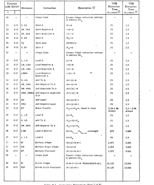
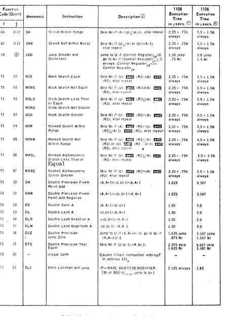
APPENDIX B. INSTRUCTION REPERTOIRE
Table B·l lists the 1106/1108 instruction repertoire in function code order. Table B·2 cross·references the mnemonic and function code.
Function 1108 1106
Code (Octal)
Mnemonic Instruction Description @ Execution Execution
Time Time
f J in {lsecs.CD in IIsecs.@
00
-
-
Illegal Code C~uses Illegal instruction interrupt-
-to address 2<U.
01 0-15 S, SA Store A (M'U .75 1.5
02 0-15 SN, SNA store Negative A -(A)~U .75 1.5
03 a-Is SM, Sr~A store Maenl tude A i(A)i"u .75 1.5
04 0-15 S, SR Store R (Ra)·U .75 1.5
05 0-15 SZ store Zero ZEROS-'U .75 1.5
-06 0'15 S, SX Store X (Xa}->U .75 1.5
07
-
-
Illegal Code Causes illegal instruclion interrupt-
-i to adqress 241.
10 0·17 L, LA Load A (U)·A .75 1.5
11 0-17 LN', LNA Load Negative A -(U}'A .75 1.5
12 0-17 LM, LMA Load Magnitude A I(U)l~A .75 1.5
13 0-17 LNMA Load Negative -1(U)i" A
•
.75 1.5Magnitude A
14 0-17 A, AA Add To A (A)j (U}-A .75 1.5
15 0-17 AN, ANA Add Negative To A (A)-(U}->A .75 1.5
16 0-17 AM, AMA Add Magnitude To A (A)+I (U ):-A .75 1.5
17 0-17 ANM, ANMA Add Negative Magnitude (A)-I(U):~A .75 1.5
to A
20 0-17 AU Add Upper (A)+(U}->A+l .75 1.5
21 0-17 ANU Add Negative Upper (A)-(U}->A+l .75 1.5
22 0·15 BT Block Transfer (Xx+u}->Xa+u; repeat K times 2.25+1.5K 3.5 + 3.0K
always always
23 0-17 L, LR Load R (U}->R a .75 1.5
24 0·17 A, AX Add To X (Xa)j(U}->X a .75 1.5
25 0-17
.
AN, ANX Add Negative To X (XaHU}->X a .75 1.526 0-17 LXM Load X Modifier (U}->X a ;Xa .
17·0 35·'8
unchanged .875 1.666
r
27 0-17 L, LX Load X (U}->X a .75 1.5
30 0-17 MI Multiply Integer (A).(U)~A,A+l 2.375 3.666
31 0·17 MSI Multiply Single Integer (A).(U}->A 2.375 3.666
32 0·17 MF Multiply Fractional (A).(U}->A,A+l 2.375 3.666
33
-
-
Illegal Code Causes illegal instrucl"ion interrupt-
-to address 241.
34 0-17 01 Divide Integer (A,A+ 1)+(U}->A; REMAINDER-'A+1 10.125 13.950
35 0·17 DSF Divide Single Fractional (A)+(U}->A+l 10.125 13.950
[image:33.613.62.564.118.721.2]..
Z9-Function 1108 1106
Cod" (():Iul)
Mnemonic: Instruc:tion Description ® Execution Execution Time Time
f j in Ilsec:s. (i) in I,secs. ®
36 0·17 OF Divide Fractional (A. AI-!)" fU I.·A; R EMAI NO E R-·A; 1 10.125 13.950
37
-
-
IIlcgal Code Causes i IIcg~1 instruction in!errupt-
-to address 141 c
40 0-17 OR Logical OR (A) m.1 {U)-A+l .75 1.5
41 0-17 XOR Logical Exclusive OR (AI r.G"J IU )-<At-! .75 l.~
42 0-11 AND Logical AN 0 (A) r:J:!1l (U)'A+I .75 1.5
43 0·17 MLU Masked Load Upper r (V) ~]l (R2)] (R2I'I·A· 1
[!13 [(A)
mm
.75 1.544 0-17 TEP Test Even parity Skip N I If (V) fJID'.l (A) have even 2_00 skip 3_00 skip
parity I. 25 N I 2.166 NI
45 0-17 TOP Test Odd Parity Skip NI if (ll) c:I!1 (A) have odd 2_00 skip 3.00 skip
parity 1.25 NI 2.166 NI
46 0-17 LXI Load X Increment (ul-'X a ; Xa unch<lng!)d 1.00 1.833
3~" 8 17-0
47 0-17 TLEM Test Less Than or Skip NI if fU)S!X a) 1.75 skip 3.333 Skip
Equal To Modifier 17·0 1.00 NI 1.833 N I
TNGM Test Not Greater alw~ys (Xa) +(Xa ) 'Xa
Than Modifier , 7-0 35-'8 17'0
50 0-17 TZ Test Zero Skip NI if (U)~~O 1.625 skip 3.166 skip
.875 NI 1.666 NI
51 0-17 TNZ Test Nonzero Skip NI if (1l)''.0· 1.625 skip 3.166 skip
.875 NI 1.666 NI
52 0-17 TE Test Equal S~ip NI if (UHA) 1.625 skip 3.166 skip
.875 NI 1.666 NI
53 0,17 TNE Test Not Equal Skip NI if (U)/(A) 1.625 ship 3.166 skip
.875 NI 1.666 N I
54 0-17 TLE Test Less Than or [qual Skip NI If (U);'::(A) 1.625 skip 3.166 skip
TNG Test Not Greater .875 NI 1.66 NI
55 0·17 TG Test Greater Skip NI if (U» (A) 1.625 skip 3.166 skip
.875 NI 1.66 NI
56 0·17 TW Test Within Range Skip NI il (Al<fUI5(A+l) 1.75 Skip 3.33 skip 1.00 N I 1.66 NI
57 0·17 TNW Test Not Within Range S~ip NI if (II';JA) or (U»(A+l) 1.75 skip 3.33 skip 1.00 NI 1.66 N I
60 0·17 TP Test POSitive Skip NI if (U),,=O 1.50 skip 3.0 skip
.75 NI 1.5 NI
61 0·17
.
TN Test Negative Skip NI if (U)35'~1 1.50 skip 3.0 skip.75 NI 1.5 NI
62 0·17 SE Search Equal Skip Nllf (U)--(A), else repeat ~ 2.25 + .75K 3.5 + 1.5K
always always
63 0-17 SNE Search Not Equal Skip N I if (U l-'I A), el se repeat 2.25 + .75K 3.5 + 1.5K
always always
64 0'17 SLE Search Less Than or Equal Skip NI if (U).$(A). else repeat 2.25 + .75K 3.5 + 1.5K
SNG Search Not Greater always always
65 0·17 SG Search Greater Skip NI if (U»(A). else repeat 2.25 + .75K 3.5 + 1.5K
always always
[image:34.613.73.530.53.685.2]Function 1108 1106
Code (OelOl)
Instruction Description 0 Execution Execution
Mnemonic
Time Time
f j in I(secs. CD in Ilsees.®
66 0·17 SW Se~rch Yllthin Range Skip NI if (A)«VI:::!AII). else repeat 2.25 t .75K 3.5 + 1.5K
always always
67 0·17 SNW Search Not \Vithln Ranp,c Skip NI if (VI;.:;tAl or (U»(Arl), 2.25 + .75K 3.5 + 1.5K
el se repe~t always always
70 ® JGD Jump Greater and Jump to Vlf (Control Register)ja>O; 1.50 jump 3.0 jump Decrement go to NI If (Control Reglstenja:> 0; .75 NI 1.5 NI
always (Control Register)ja-I ... Control Regl stcrja
71 00 MSE Mask Search Equal Skip NI il (V) tm (R2)~(A) flm) 2.25 + .75K 3.5 + 1.5K
(R2), else repeat always always
71 01 MSNE Mask Search Not Equal Skip NI if iU) rnrn (R2);i(A)
a::m
2.25 + .75K 3.5 + 1.5K(R2). el se rl'pe~t always always
71 02 MSLE Mask Search less Th~n Skip NI if (V) t1'm] (R2)DA) Em 2.25 + .75K 3.5 + 1.5K
or Equal (R2). else repeat
.
always alwaysMSNG Mask Search Not Greater
71 03 MSG Mask Search Greater Skip NI if IV)
mm
IR2)"'(A) Em!! 2,25 + . 75K 3.5 + 1.5K(R2), else repeat always always
71 04 MSW , Masked Search Wi thin Skip NI if iA) rJmJ (R2)«V) l'I:m 2.25 + .75K 3.5 + 1.5K Range (R2)~(AI-I) r.:m!l IR2). else repeat always always
71 05 MSNW Masked Search Not Skip NI if (U) F..1ml (R2)«A)
mm
2.25 + .75K 3.5 + 1.5K Within Range (R2) or IU) !'J.r.!l (R 2, .-: A' I) 'a:I!l always always(R2), els~ rcpc,'t
,
71 06 MASL Masked Alphanumeric Skip NI if IU) I'l:Ii] (R2)':;:IA)
me
2.25 + .75K 3.5 + 1.5KS~arch l.ess Than or
Equal (R21. else repeat always always
71 07 MASG Masked Alphanumeric Skip NI if IU) tmiJ (R2»(A) rJ:m 2.25 + .75K 3.5 + 1.5K
Search Greater (R2). else repeat always always
11 10 DA Double Precision Fixed· (A,A+l}+( V,VI-I J-+A.A+I 1.625 3.167
Point Add
71 11 DAN Double P