A Novel Three Phase Asymmetric Multi Level Inverter Fed To
Induction Motor Drive
D. Nagendra Babu
11
Asst Professor, Dept of EEE, Vaagdevi Institute of Technology and Science, Proddatur, YSR DIST. AP, INDIA
.Key Terms- Three phase asymmetric, multilevel inverter, h-bridge basic units, induction motor.
1. INTODUCTION
Over many years, Induction motor drives have been popularly used for variable speed control applications in industries. In recent years, Multi Level Inverters (MLI’s) are more popular because of their huge advantages over than the conventional inverters. The main advantages of MLI’s are lower voltage changing rate, lower total harmonic distortion (THD), lower amount of switching loss and better power quality.
The cascaded MLI’s (CMLI’s) are gaining popularity because of easy control, easily identification of error circuits and modularity of the devices. Cascaded MLI’s are categorized based upon their using dc sources are as follows,
1) Symmetric CMLI’s and
2) Asymmetric CMLI’s
Symmetric CMLI’s are having same magnitude of applied voltages on both sides of the inverter. Asymmetric CMLI’s are having different magnitudes of applied voltages on both sides of inverter. Asymmetric CMLI’s are generate more number of levels at the output than the symmetric CMLI’s. Symmetric CMLI’s are having bidirectional switches includes driver circuit, two number of IGBT’s and power diodes if that may leads the increasing of total cost of an inverter and installation space also be increased. Different symmetric CMLI’s are on [5]. Asymmetric CMLI’s are having unidirectional switches from voltage point of view and bidirectional switches from the current point of view. Unidirectional switches include of an IGBT with an antiparallel diode. Different Asymmetric CMLI’s are on [6].
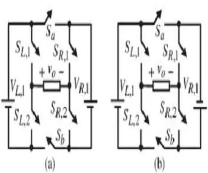
The proposed one is developed by using a new single-phase H-bridge basic units[1].
---***---
International Research Journal of Engineering and Technology (IRJET) e-ISSN: 2395-0056
Volume: 06 Issue: 01 | Jan 2019 www.irjet.net p-ISSN: 2395-0072Fig 1: Seven Level Inverters. (a) First Proposed Topology (b) Second Proposed Topology.
Table 1:OUTPUT SEQUENCE VOLTAGES OF A H-BRIDGE
Considering Table I, to generate all voltage levels (odd and even) in the proposed topology. From the table I, we observes the three positive levels, three negative levels and one zero level are generate by using single bridge. By cascading the two h-bridges, we are generate 49 levels with a maximum amplitude of output voltage.
II. PROPOSED TOPOLOGY
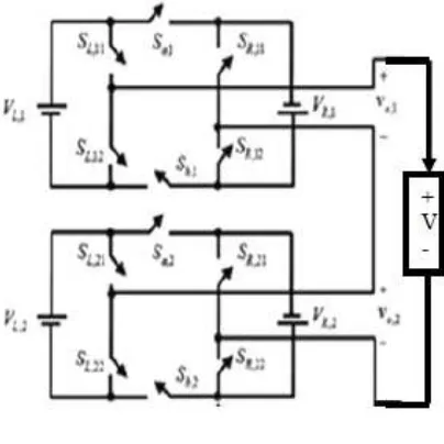
[image:2.612.202.410.336.533.2]Fig 2: Asymmetric 49-Level Inverter
The proposed topology for single-phase Asymmetric 49-level inverter is shown in Fig 2.
The power switches of each leg is activated simultaneously that means for each and every switching pattern, the switches SL,1 or SL,2, SR,1 or SR,2, SA or SB of a single h-bridge.
Magnitudes of dc voltage sources for a single h-bridge is
VR,1=Vdc (1)
VL,1=2Vdc (2)
The total output voltage is determined by the equation,
Vo(t)= Vo,1(t)+ Vo,2(t) (3)
Vo,1(t) is the maximum voltage at the output of first h-bridge,
Vo,1(t)=VR,1+VL,1=3Vdc (4)
Vo,2(t) is the maximum voltage at the output of second h-bridge,
Vo,2(t)=7VR,1+7VL,1=21Vdc (5)
Hence the total output voltage of proposed system is
Vo(t)= Vo,1(t)+ Vo,2(t)=24Vdc (6)
Then the output voltage from peak to peak is
Vp-p=2 Vo(t) (7)
The blocked voltages by all IGBT’s in the first bridge is
International Research Journal of Engineering and Technology (IRJET) e-ISSN: 2395-0056
Volume: 06 Issue: 01 | Jan 2019 www.irjet.net p-ISSN: 2395-0072The maximum amount of blocked voltages in the proposed system is
Vblock=4(VR,1+VL,1+VR,2+VL,2) (9)
III. PERFORMANCE OF A THREE-PHASE ASYMMETRIC INVERTER FED INDUCTION MOTOR
Asymmetric inverter has four dc voltage sources having ranges are VR,1=10V, VL,1=20V, VR,2=70V and VL,2=140V.
An electric motor convert’s electrical power to mechanical power in its rotor. Induction motors are widely used, especially poly phase induction motors, which are frequently used in industrial drives. When induction motors are given supply, Motor draws a very high current initially, due to which voltage dip will forms, which show the effect on the power system network. In order to avoid voltage dip, we employ new controller to generate more levels at ouput voltage.
[image:4.612.195.423.268.453.2]IV. SIMULINK MODELS AND RESULTS
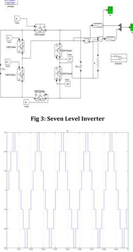
[image:4.612.195.413.276.688.2]Fig 3: Seven Level Inverter
Fig 6: Output Voltage
International Research Journal of Engineering and Technology (IRJET) e-ISSN: 2395-0056
Volume: 06 Issue: 01 | Jan 2019 www.irjet.net p-ISSN: 2395-0072 [image:6.612.168.446.85.685.2]Fig 7:Three-Phase Asymmetric Inverter
Fig 8: Three-Phase Current and Voltage
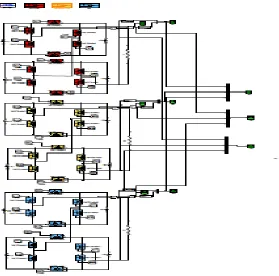
[image:6.612.166.445.101.377.2]Fig 10: Three-Phase Mli Fed to Induction Motor Drive
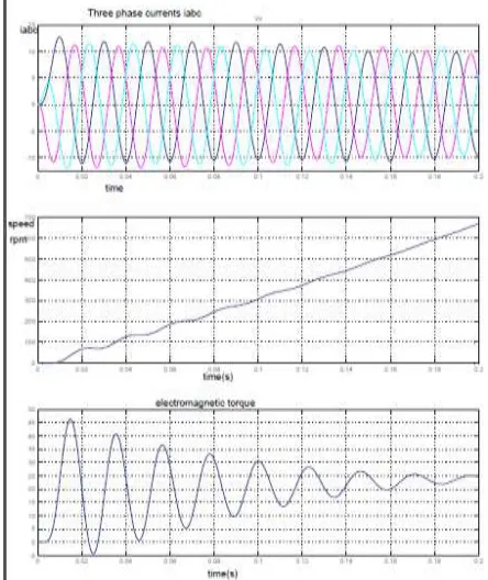
Fig 11: Induction Motor characteristics, (a)Iabc , (b)Rated speed and (c) Electomagnetic Torque
V. CONCLUSION
[image:7.612.194.416.337.601.2]International Research Journal of Engineering and Technology (IRJET) e-ISSN: 2395-0056
Volume: 06 Issue: 01 | Jan 2019 www.irjet.net p-ISSN: 2395-0072number of IGBTs, power diodes, driver circuits, and dc voltage sources. Moreover, the magnitude of the blocking voltage of the switches is lower than that of conventional topologies. However, the proposed topology has a higher number of varieties of dc voltage sources in comparison with the others. The proposed topology was verified through the matlab/Simulink platform through 49-level inverter.
V. REFERENCES
[1] D.Nagendra Babu, M.Mahesh, M.Rama Sekhara Reddy “A Novel Three Phase Asymmetric Multi level Inverter with Series H-bridges “International Research Journal of Engineering and Technology (IRJET) Volume: 03 Issue: 10 | Oct-2016
[2] Ebrahim Babaei, Sara Laali, and Somayeh Alilu, “Cascaded Multilevel Inverter With Series Connection of Novel H-Bridge Basic Units,” IEEE transactions on industrial electronics, vol. 61, no. 12, december 2014.
[3] E. Babaei and S. H. Hosseini, “Charge balance control methods for asymmetrical cascaded multi level converters,” in Proc. ICEMS, Seoul, Korea, 2007, pp. 74-79.
[3] S. Laali, K. Abbaszades, and H. Lesani, “A new algorithm to determine the magnitudes of dc voltage sources in asymmetrical cascaded multilevel converters capable of using charge balance control methods,” in Proc. ICEMS, Incheon, Korea, 2010, pp. 56-61.
[4] M. Narimani and G. Moschopoulos, “A novel single stage multilevel type full-bridge converter,” IEEE Trans. Ind. Electron., vol. 60, no. 1, pp. 31– 42, Jan. 2013.
[5] E. Babaei, M. Farhadi Kangarlu, and F. Najaty Mazgar, “Symmetric and asymmetric multilevel inverter topologies with reduced switching devices,” Elect. Power Syst. Res., vol. 86, pp. 122-130, May 2012.
[6] J. Ebrahimi, E. Babaei, and G. B. Gharehpetian, “A new topology of cascaded multilevel converte -rs with reduced number of components for high-voltage applications,”IEEE Trans. Power Electron., vol. 26, no. 11, pp. 3109–3118, Nov. 2011. [7]G. Waltrich and I. Barbi, “Three-phase cascaded multilevel inverter using power cells with two inverter legs in series,” IEEE Trans. Ind. Appl., vol. 57, no. 8, pp. 2605-2612, Aug. 2010.
[8] N. Farokhnia, S. H. Fathi, N. Yousefpoor, and M. K. Bakhshizadeh, “Minimisation of total harmonic distortion in a cascaded multilevel inverter by regul -ating of voltages dc sources,” IET Power Electron., vol. 5, no. 1, pp. 106-114, Jan. 2012.
[9]N. Abd Rahim, M. F. Mohamad Elias, and W. P. Hew, “Transistor-clamped H-bridge based cascaded multilevel inverter with new method of capacitor voltage balancing,”IEEE Trans. Ind. Electron., vol. 60, no. 8, pp. 2943– 2956, Aug. 2013.
[10] K. Ding, K. W. E. Cheng, and Y. P. Zou, “Analysis, of an asymmetric modulation methods for cascaded multilevel inverters,” IET Power Electron.,vol. 5, no. 1, pp. 74-85, Jan. 2012.
Author’s Profile