© 2019, IRJET | Impact Factor value: 7.211 | ISO 9001:2008 Certified Journal | Page 4868
Effect of Tubercles on Aerodynamic Performance of NACA 0015
Hardeep Singh Lall
1, Jaitra Khanna
2, Harsh Khatri
3, Sahil Mhapankar
4, Parmeshwar Paul
5Anjali. A. Vyas
61,2,3,4
Student, Dept of Mechanical Engineering, MCT’s Rajiv Gandhi Institute of Technology, Versova.
5,6
Assistant Professor, Dept of Mechanical Engineering, MCT’s Rajiv Gandhi Institute of Technology, Versova.
---***---Abstract -
This study investigates the effect of leadingedge tubercles on the aerodynamic performance of a NACA 0015 airfoil by using the Ansys CFX solver and also investigates how the change in amplitude of the tubercles affects its performance. The tubercle model results are compared with those of the straight leading edge. The analysis was also carried out on three different amplitudes of airfoil by keeping the wavelength same and their results were compared. The analysis was carried out at speed of 95 m/s corresponding to a Reynolds Number of 5.005x10^5 and for angle of attacks ranging from 0-30⁰ with a step of 2⁰. The results obtained showed that the tubercle airfoil gave better lift co-efficient in the post-stall region and also delayed the stall phenomenon by at least 4⁰. It was found that the lift co-efficient of straight leading edge (basic) airfoil was better than those of tubercle in pre-stall region. Further, on comparison of the tubercles with different amplitudes, it was observed that varying the amplitude and wavelength results in change in performance and thus, changing the amplitude and wavelength may provide better performance in both the pre-stall and post-stall region.
Key Words
:
Tubercles, Humpback whale, CFD, NACA 0015, Stall angle, Angle of Attack, Ansys CFX.1. INTRODUCTION
Airfoil has a variety of applications ranging from airplane wings to compressors, fans, turbines, etc.
Improvement in the performance of the airfoil can significantly increase the efficiency of such systems which means less power consumption and thus cost benefits. In case of airplanes, it means less fuel consumption and thus lower pollution.
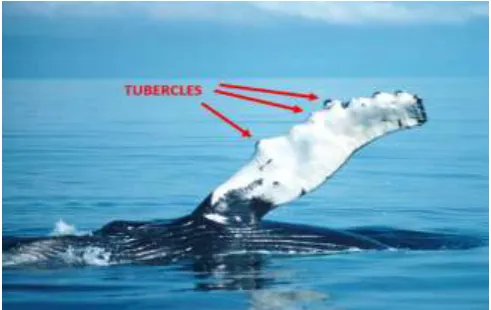
Tubercles are large bumps on the leading edge of an airfoil which provides a conditionally better performance. The idea of this modification was biologically-inspired based on the fin shape of humpback whales. These baleen whales, despite their massive size are extremely agile and can perform maneuvers under water. The reason for this was the shape of their fins which had tubercles on the leading edge.
1.1
Literature Survey
There is a lot of research being carried out in the field of tubercle airfoil for various profiles of the airfoil and for varying Reynolds Number and Angle of Attack (AoA).
Watts and Fish[4] analysed the flow over NACA 63-021 with and without sinusoidal tubercles and at large Reynolds Number. They found that for 10⁰ AoA, the increase in lift was 4.8%, while reduction in drag was 10.9% and Lift to Drag (L/D) increased by 17.6%.
D.S. Miklosovic and M.M. Murray[2] carried out wind tunnel testing of an idealized humpback whale fin model at high Reynolds Number and found that the tubercles delay the stall angle by approximately 40%, while incresing lift and reducing drag.
Stein and Murray[1] and Johari et al conducted experiments on tubercle full span airfoils similar to those of whale at low Reynolds Number. They found that the performance in pre-stall region is inferior for tubercle airfoil as compared to the basic one but found that it provides softer stall characteristics and more lift in the post-stall regime as compared to basic airfoil.
[image:1.595.35.281.579.734.2]K.L. Hansen[3] compared the performance of basic NACA 0021 airfoil with the tubercle airfoilhaving amplitude in the range of (0.03-0.11)*chord length and wavelength in the range of (0.11-0.43)*chord length. The chord length selected was 70 mm. Their results showed that the airfoil with tubercles delayed stall, while the enhancement in performance was insignificant.
© 2019, IRJET | Impact Factor value: 7.211 | ISO 9001:2008 Certified Journal | Page 4869
Z. Čarija, E. Marušić [5] carried out comparison of NACA0012 airfoil with straight leading edge and sinusoidal tubercles at Reynolds Number of 1.8x10^5 and found that the bumped blade showed better results at certain angle of attack. At AoA larger than 10⁰, they exhibited an increase in lift by (3-9.5) % and decreased drag. It also delayed the stall angle by approximately 5⁰.
This study is an attempt to understand the effect of tubercles on NACA 0015 at a Reynolds Number of 5.005x10^5 and also note the changes in performance due to changing amplitude.
2. AIRFOIL DESIGN
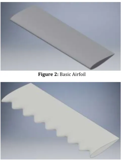
[image:2.595.315.559.296.504.2]The airfoils (both basic and tubercle) were based on the symmetric NACA 0015 profile. The chord length of the baseline profile is 74 mm and the span of both the airfoils is 240mm. The co-ordinates for the airfoil were obtained from online airfoil plotter website.
Figure 2: BasicAirfoil
Figure 3: Mid-amplitude tubercle Airfoil
The tubercles were built sinusoidally with amplitudes in the range of (0.05-0.11)*chord length. The amplitude of 0.05405xLc = 4mm is for the small-amplitude tubercle and 0.08108xLc =6mm and 0.1081xLc =8mm are amplitudes of mid-amplitude and large-amplitude tubercles respectively. The wavelength in all these three cases is the same i.e.0.4054xLc=30mm.
The tubercles were built by scaling the profiles. In case of mid-amplitude tubercles the profile was scaled at 1.081 times of the baseline profile to form crest region of tubercles and the profile was scaled at 0.9189 times of baseline profile to form trough region. The profiles are spaced equally at a distance of 7.5mm from each other at proper locations to form the sinusoidal shape of desired wavelength and amplitude. The other tubercle airfoils were designed in similar way.
3. GEOMETRY AND DOMAIN
The CAD models of the airfoils were built by using Autodesk Inventor.
The domain selected for the analysis is shown in Figure 4.
Figure 4: Domain
The inlet section selected is of C-type based on previous research studies. The inlet was kept at the distance of 0.3m i.e. 4.054xLc .The center of the C-section is at 0.05m i.e. 0.676xLc. The outlet section was kept at 0.5m i.e. 6.757xLc. The outlet section was comparatively far away, in order to eliminate the influence of the backflow on the results. The upper and lower edges were both kept at a distance of 0.25m (3.378xLc) each from the leading edge of tubercle.
4. MESHING
[image:2.595.35.277.328.644.2]© 2019, IRJET | Impact Factor value: 7.211 | ISO 9001:2008 Certified Journal | Page 4870
Figure 5: Complete mesh view of basic airfoilThe mesh which was selected for the study did not distort the shape of the tubercles as seen in Figure 6. The close-view of the selected mesh around the tubercles is as shown in Figure 7.
[image:3.595.316.567.225.469.2]Figure 6: Distorted tubercle due to meshing
Figure 7: Close view of mesh on tubercle airfoil without distortion
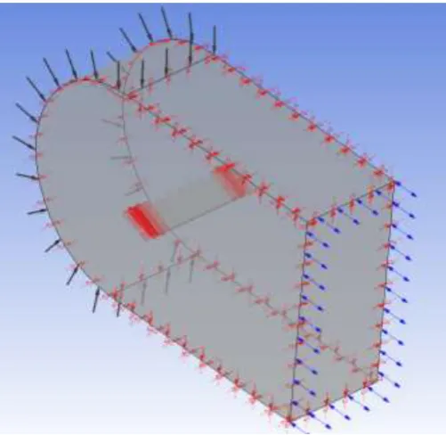
5. SETUP AND BOUNDARY CONDITIONS
The proper specification of boundary conditions is an essential part of any CFD analysis.
The inlet condition specified at the inlet section is the velocity of flow, which is 95m/s in the x-direction. The fluid used for the analysis is Air at 25⁰C.
Problem At the outlet section, an opening is specified with the gauge pressure of 0 Pa.
[image:3.595.37.280.326.464.2]All the remaining wall sections are specified as slip walls (i.e. the viscous effect at these walls is neglected) by specifying the symmetry boundary at these walls. The airfoil body is defined as a no-slip wall.
Figure 8: Boundary conditions
6. COMPUTATIONAL MODEL
The flow over the airfoil was in high Reynolds number range and hence, it was necessary to take into account the turbulence. Therefore, the Reynolds Averaged Navier Stokes (RANS) with SST turbulence model was selected. The SST turbulence model has the advantage of k-ω model of better near-wall performance and it switches to k-ε model in free-stream and thus, avoids the problem of the k-ω model being too sensitive to the inlet free-stream turbulence properties.
The SST model is a popular choice in Aeronautical area because of its ability to better predict the separation and reattachment.
The value of y+ was kept less than 1 by using inflation to justify the use of SST model.
[image:3.595.39.280.495.643.2]© 2019, IRJET | Impact Factor value: 7.211 | ISO 9001:2008 Certified Journal | Page 4871
7. RESULTS AND CONCLUSIONS
The results obtained by this study are for the wavelength and amplitude specified as above and for the Reynolds Number of 5.005x10^5.
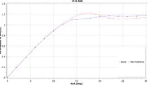
[image:4.595.317.560.279.411.2]The following figure shows the graph of values of co-efficient of lift (cl) vs the Angle of Attack (AoA).
Figure 10: cl vs AoA for basic and mid-amplitude tubercle airfoil
From Figure 10 it can be inferred that for angle of attack ranging from 0⁰ to 14⁰, the co-efficient of lift for both the airfoils is approximately the same. Therefore in this region, the lift performance of both the airfoils is the same. Further, it can be seen that the basic airfoil stalls at the angle of around 18⁰, whereas the tubercle airfoil stalls at around 22⁰. Thus, the tubercles delay the stall crisis by approximately 4⁰ i.e. it increases stall angle by 22.22%.
In the range of angles 14-21⁰, around stall of basic airfoil, the lift performance of tubercle airfoil is lower than that of the basic airfoil. Also the maximum lift co-efficient of basic airfoil is greater than that of the tubercle one.
But the tubercle airfoil provides better lift performance in the post-stall region. In the post-stall region the co-efficient of lift of the tubercle airfoil is (3.5 - 5.2) % greater than that of the basic airfoil.
Thus, the main advantage of the tubercles is that they delay stall and provides better post-stall performance.
However, it reduces the maximum co-efficient of lift that can be obtained.
The comparison of lift co-efficient of the tubercle airfoils with three different amplitudes is shown in Figure 11. It can be seen that as the amplitude of the tubercles is reduced the co-efficient of lift increases. Thus, as the amplitude of tubercles change, their lift performance also changes.
The Figure 12 shows the graph of cl vs AoA for the basic and small amplitude tubercle. The performance of tubercle airfoil is better than that of basic airfoil in 0-140 and 20-300 range and is lower than that of basic only in the narrow range of 14-200.
[image:4.595.317.558.288.525.2]
Figure 11: cl vs AoA for three different amplitudes of tubercles
Figure 12: cl vs AoA for basic and small-amplitude tubercle
In this study, the wavelength of the tubercles has been kept constant. However, the wavelength variation may also affect the results obtained. Thus, by changing the amplitude and the wavelength of the tubercles the performance of the tubercle airfoil can be improved both in the pre-stall and post-stall region. Elaborate wind tunnel testing can be carried out to determine the cause of poor performance in the 14-210 range.
The values of co-efficient of drag vs the Angle of Attack for basic as well as the tubercle airfoil is as shown in the Figure 13.
[image:4.595.38.279.319.458.2] [image:4.595.317.560.386.588.2]© 2019, IRJET | Impact Factor value: 7.211 | ISO 9001:2008 Certified Journal | Page 4872
It is seen that the drag in case of tubercle airfoil in therange of 0⁰ - 14⁰ is slightly lower than or equal to that of the basic airfoil. Thus, tubercle airfoil in this range provides slightly better drag performance than that of the basic airfoil. However, in range of 14⁰ - 22⁰, it is seen that the drag for tubercle airfoil is higher than that in case of the basic airfoil. This is the region in which the basic airfoil obtains maximum lift co-efficient. As AoA is further increased the cd for both the airfoils increases.
[image:5.595.317.560.122.263.2]However, the rate of increase is lower in case of mid-amplitude tubercle airfoil. Therefore, in post-stall region it will provide slightly lower drag.
Figure 13: cd vs AoA for basic and mid-amplitude tubercle airfoil
[image:5.595.41.279.256.392.2]The variations in the values of drag due to amplitude are as shown in the Figure 14.
Figure 14: cd vs AoA for three different amplitudes of tubercles
It is seen that the drag for the three tubercles is nearly the same or slightly lower in large-amplitude tubercle in the 0 - 12⁰ range. Above 12⁰ the drag is slightly higher for the large-amplitude tubercle which experiences the lowest lift in this region. However, in the post stall region the rate of increase of cd for large-amplitude tubercle is lower than that of all the three tubercles and the rate of increase of mid-amplitude tubercle is lower than that of small-amplitude tubercle.
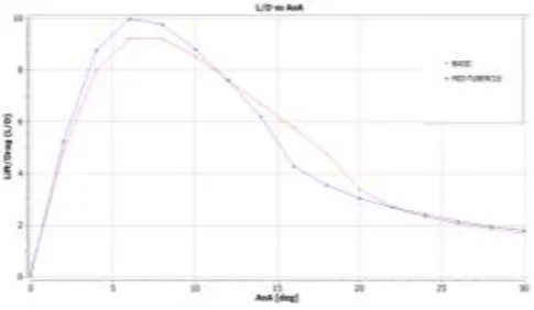
[image:5.595.318.559.439.577.2]The Lift to Drag (L/D) ratio for the basic and the tubercle airfoil is as shown in Figure 15.
Figure 15: L/D vs AoA for basic and mid-amplitude tubercle
It is seen that the tubercle airfoil provides higher L/D ratio in the pre-stall region from 0 - 12⁰. The L/D ratio for the tubercle airfoil is lower than that of basic in 14 - 22⁰ range which is the region in which the basic airfoil achieves maximum lift co-efficient.
Above 220, the L/D ratio for mid-amplitude tubercle is again slightly greater than that of the basic airfoil.
The variation of L/D due to change in amplitude is as shown in Figure 16.
Figure 16: L/D vs AoA for three different amplitudes of tubercles
[image:5.595.39.280.486.624.2]© 2019, IRJET | Impact Factor value: 7.211 | ISO 9001:2008 Certified Journal | Page 4873
8. VALIDATION
It is a known fact that in case of a symmetric airfoil at 0˚ angle of attack, there is no lift generation i.e. the lift is nearly zero. This is due to the fact that in this case the air flows over and under the airfoil with the same velocity and hence, the pressure generated above and below the airfoil is the same. Therefore, there is no pressure difference over the airfoil in case of symmetric airfoils such as the one selected. The plot of co-efficient of pressure (cp) obtained at 0˚ by using the simulation mentioned above satisfies this condition, thus providing a surety of the method being correct.
[image:6.595.41.280.309.466.2]
where, subscript ∞ denotes free stream conditions.
Figure 17: Co-efficient of pressure for basic airfoil at zero AoA
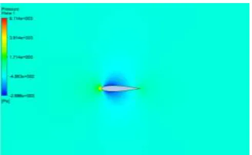
From the cp plot we can see that the pressure difference between upper and lower surface of the airfoil is zero as the pressure lines at upper and lower surface nearly coincide with each other. The same can be seen in the pressure contour shown below.
Figure 18: Pressure contour at zero AoA for basic airfoil
Further, from airfoiltools.com[6], it was found that the basic NACA 0015 airfoil stalls at an angle of around 17˚. In this study, the stall is obtained at an angle of around 18˚ which is nearly the same. Thus, providing a further surety of the method being correct.
A sanity check is also carried out on the process by verifying whether the mass conservation equation is satisfied or not.
At inlet section, the mass flow rate obtained is 13.509 kg/s. At the outlet section, the mass flow rate is -13.509 kg/s. The negative sign indicates that the fluid is flowing outside the domain at the outlet. The mass flow rate through the symmetry wall region is obtained as around -2.865x10^ (-16) i.e. approximately zero. Thus, the mass conservation equation is satisfied.
References
[1] B. Stein, M.M. Murray. "Stall Mechanism Analysis of Humpback Whale Flipper Models." International symposium; 14th, Unmanned untethered submersible technology. Durham, 2005.
[2] D. S. Miklosovic, M. M. Murray. "Leading-edge tubercles delay stall on humpback whale (Megaptera novaeangliae) flippers." Physics of Fluids Volume 16. 2004.
[3] K.L. Hansen, R.M. Kelso. "An Investigation of Three-Dimensional Effects on the performance of Tubercles at Low Reynolds Numbers." 17th Australasian Fluid Mechanics Conference. Auckland, New zealand, 2010.
[4] P. Watt, F.E. Fish. "The influence of Passive Leading Edge Tubercles on Wing Performance." Unmanned Untethered Submersible Technologies (UUST). Durham, 2001.
[5] Z. Čarija, E. Marušić. "Numerical Analysis of Aerodynamic Characteristics of a Bumped Leading Edge Turbine Blade." Engineering Review Vol 34, Issue 2. 2014.
[image:6.595.36.282.541.692.2]