Analyzing Uncertainties of Rectangular Periodic
Defected Ground Structure Characteristics
Prakash K Kuravatti
EEE Dept BTLIT Bangalore Karnataka
T.S. Rukmini
PhD, ECE Dept NMIT Bangalore Karnataka
ABSTRACT
The defected ground structure (DGS) is one such technique which where intentionally modified to enhance the performance of the ground plane metal of a microstrip circuit. Importantly, in microwave application, the DGS plays an important role in analyzing the effect of surface and leaky waves. During the time of experimental analysis, the surface and leaky waves are affected by the propagation uncertainties. Hence, the performance of microstrip circuit is also affected. So, proper mathematical model is needed for analyzing the propagation uncertainty of DGS and to improve the performance. In this paper, the curve fitting mathematical model is proposed for analyzing the propagation uncertainty. In the proposed model, the bi-segmentation process is applied to the experimental characteristics. The proposed curve fitting model is implemented and the Rectangular Periodic defected ground structure propagation uncertainties are analyzed.
Keywords
DGS, Propagation Characteristics, Experimental Model, Mathematical Model, Curve Fitting, Uncertainty.
1. INTRODUCTION
Currently, the defected ground structure (DGS) is gaining much attention in the fields of microwave and millimeter wave applications [1]. It is extensively used in microwave circuit design such as power divider, power amplifier and specifically in filter design [3] [20]. High performance, compact size and low expense often meets the stringent requirements of modern microwave communication systems [4]. Ultra-wideband (UWB) technology has turned into one of the most competent solutions for future short-range high-speed indoor data communication applications [9]. Nowadays, there is an increasing interest in developing UWB radio for short-range high-speed wireless communication networks [10]. DGS is realized by engraving off a simple shape defect from the ground plane. The shielded current distribution in the ground plane is disturbed based on the shape and dimensions of the defect, resulting in a controlled excitation and propagation of the electromagnetic waves via the substrate layer [5]. The effect of DGSs is to place parallel inductance and capacitance in the lumped model, which includes a pole to the transfer function and results in a resonant frequency [7]. DGS has the characteristics of stop-band, slow-wave effect, and high impedance that have been created to reduce the harmonics as well as to realize the compact physical dimensions of RF circuits [8].
Today, DGS for the microstrip lines that has engraved defects in the backside metallic ground plane has become one hot area in microwave integrated circuits (MIC) design [6] [16]. In numerous wireless communication systems, microstrip patch antennas are utilized widely because of their several benefits such as low profile, light weight, easy fabrication and
conformability to mounting structure [12] [18]. EBG structures realized on metal layers are helpful for creating filters such as band-stop filters, low-pass filter, phase shifters and antennas [15]. Numerous shapes of DGS slot have been studied in planar microstrip antenna designs, which provides better performances- size diminution (lower resonant frequency), impedance bandwidth enhancement (lower quality factor), and gain increasing [11]. DGS have received substantial interests, because they can refuse certain frequency bands, and hence it is called electromagnetic band gap (EBG) structures [2]. DGS and the Electromagnetic band gap (EBG) structures, generally called as the photonic band gap structures (PBG), are the two diverse types of generic structures employed for the design of the compact and high performance microwave components [13]. Application of DGS and EBG will minimize the dimensions of the divider as well as improves its scattering parameters [7]. Periodic structures have received a great attention in diverse antenna applications namely, frequency selective surfaces, corrugated horn antenna, and leaky wave antennas [17]. DGS also has a periodic structure, but it is simple to construct, because DGS patterns are realized when the PCB of the amplifier circuit is engraved at the same time [19].
The DGS reduce the mutual coupling between the microwave antenna array elements. The effect of mutual coupling increases the propagation uncertainty of microwave antenna. So, the accuracy of the propagation of microwave is affected and more chance for occurring confliction in the DGS size. To overcome this problem, a curve fitting mathematical model for analyzing the experimental model uncertainty is proposed in this paper. The function of the proposed curve fitting mathematical model is to determine the size of the DGS. The detailed problem formulation and the proposed curve fitting model are described in Section 3. Before that, the recent related researches are analyzed in Section 2. In Section 4, the results and discussion of the proposed model is described. In Section 5, conclusion of the paper is given.
2. RELATED RESEARCH WORK: A
REVIEW
suppression was below −41 dBc in the frequency double mode with the stop band characteristic of DGS. The proposed transmitter has utilized a GaAs InGaP Hetero junction broadband MMIC. It has achieved 13.7dBm of P1dB and its gain was 16.5 dB in amplifier mode, and its maximum output power was 7.8dBm at 6.8 GHz in frequency double mode. Susanta Kumar Parui et al. [22] have designed a popular split-ring type defected ground structure under a microstrip line by an equivalent circuit. The frequency characteristics of the proposed unit cell have shown an attenuation zero close to its attenuation pole frequency. A 3rd order elliptic low pass filter has been designed by the proposed DGS. Also, the equivalent LC parameters have been extracted. The effect of split-gap variation for the DGS unit on pole and cutoff frequencies has been investigated. Two DGS cells with diverse pole frequencies cascaded under a microstrip line has obtained a sharp and deep low pass filter. The pass band insertion loss has been minimized through a high-low impedance line instead of using the standard line. A prototype filter has been constructed with Arlon substrate. The simulated S-parameters have been compared with its experimental measurement results.
A DGS, which has better slow-wave effect than the cross or dumbbell one has been proposed by J. X. Liu et al. [23]. Its equivalent parameters have been extracted using the model of transmission line. Then, the proposed DGS with good omni-directional properties has been employed in the design of a proximity coupled antenna for increasing its efficiency. The size of the developed antenna was about 68% smaller than that of the traditional one. Moreover, the protrudent stub length has been diminished from 26.9mm to 18.94 mm by adding two artificial cells on the feed line. Finally, the size of proximity coupled antenna has been diminished substantially by means of the DGS and artificial cells.
For the dumbbell-shaped DGS, Yuchun Guo et al. [24] have proposed an enhanced equivalent circuit parameters extraction technique. The equations for the parameters extraction have been obtained in closed-form expressions, which have S11 and S21. The DGS unit with center frequency of 5 GHz has been designed and constructed on a TLX substrate with thickness of 1 mm and dielectric constant of 2.55. The circuit simulated results are in good concurrence with the measured results. The proposed parameters extraction technique has been extensively exploited for the design and analysis of DGS.
The effect of inserting a rectangular shape DGS into the ground plane of the conventional rectangular microstrip patch antenna (CRMPA) has been described by Mouloud Challal et al. [25]. The performances of the CRMPA have been characterized by changing the dimensions of the rectangular slot (RS-DGS) as well as by placing the RS-DGS at particular position.
Tamasi Moyra et al. [25] have developed a modified Pi shaped microstrip DGS structure. The elliptic function response and almost ideal low pass filtering characteristics have been exhibited by the proposed DGS. The stop band has been tuned by altering the length and width of the connecting transverse slot. A substantial improvement in insertion loss has been achieved by including capacitively loaded microstrip line or alternative transmission line above DGS. Also, the circuit size has been reduced by this approach. A three-pole LPF has been realized by integrating three DGS units of diverse dimensions under capacitive loaded microstrip line.
3. PROBLEM STATEMENT AND
PROPOSED METHODOLOGY
In the related work section, the different kinds of DGS structures and their propagation characteristics are analyzed. The propagation characteristic of DGS is varied based on their structure changes and it affects the performance of designed microwave antenna. So, the propagation uncertainty is occurred. Hence, an analytical model is needed for analyzing the propagation characteristics uncertainty of DGS structure. In existing works, there is no proper model for analyzing the uncertainty of wave dispersion and transmission characteristics of DGS structures. The reason for occurring propagation uncertainty is the gap between adjacent slots of DGS. The model determines the performance of DGS structures and realizes the slow wave effect. When the DGS structure is used without proper model, the performance, slow wave effect, and Q-factor are affected. Moreover, the surface wave polarization of DGS structure is also affected by the microwave integrated circuit. In this paper, an integrated multi-segmentation curve fitting mathematical model is proposed for analyzing the propagation characteristics and the propagation uncertainty of DGS structure. The proposed mathematical model is based on the Rectangular Periodic DGS and their microwave propagation characteristics. The Rectangular Periodic of DGS, the equivalent circuit model, and the proposed methodology are described in the following section.
3.1. Rectangular Periodic DGS and
Equivalent Circuit
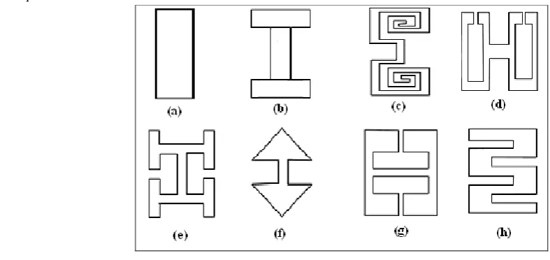
Defected Ground Structures (DGS) are implemented by etching slots Rectangular shape in the ground planes. They have been employed to improve the performance in multiple applications such as filters, couplers or dividers, microwave circuits as well as to reduce the mutual coupling between the elements of antenna arrays [27]. In this application, the parameters considered are the shape of unit DGS, the distance between two DGS, and the distribution of Rectangular Periodic DGS. As well as the DGS can improve the performance of the antenna, restrain harmonious, and decrease the mutual coupling of antenna array by containing the surface waves. The additional equivalent components and the increased slow wave effect are the important properties of DGS because, it can be realized and the equivalent circuit can be reduced using these properties. Some of the DGS units and the structures are described in Fig.1.
The equivalent circuit model of the DGS element is used to
measure the propagation characteristics of DGS unit. The equivalent value of resistance (R), inductance (L), and capacitance (C) are determined by the dimensions of the DGS structure and its position relative to the transmission line. In this equivalent circuit, the parallel tuned circuit is connected in series with the transmission line. The value of R, L and C.
are obtained by using the following equation. Where,
f
0is the resonance frequency,
is the angular frequency,
0isthe
resonance angular frequency, and
cis the cut off angular frequency of the RLC resonator. In this DGS, the dispersion of microwaves and the surface wave power transmission characteristics are analyzed. Then, from these propagation characteristics, the propagation uncertainty is analyzed by the proposed curve fitting model. An accurate curve fitting results obtained by the curve fitting model is used to determine the size of the DGS. Also, it is used to choose an exact equivalent circuit parameter for the required inductance. The proposed curve fitting model is discussed deeply in the following section..
3.2. Curve Fitting Mathematical Model
The curve fitting is the process of developing mathematical model and analyzing the best possible fit of a curve. The Mathematical model is developed from the characteristics of experimental data. In this paper, a multi segmentation based curve fitting method is developed. The objective of the proposed method is to segment the propagation characteristics and to develop an integrated model of the corresponding segment characteristics. From the integrated model, the uncertainty of the segmentation characteristics is analyzed. The experimental data is obtained from the propagation characteristics of Periodic Defected Ground Structure (PDGS). Then, the curve fitting based generated model is chosen as the reference model and using the reference model, the propagation uncertainty of the experimental data is determined.
In Fig.1, Rectangular Periodic DGS structure are chosen to develop the curve fitting mathematical model and analyze the propagation uncertainty.. Then, the considered DGS structures dispersion and the surface power transmission of microwave are analyzed. In the considered characteristics, the curve fitting process is applied. The curve fitting process is performed by polynomial curve data points.
The steps used for developing the curve fitting mathematical model are described as follows.
[image:3.595.59.453.81.267.2]Figure 1: Different DGS Unit and Structure
.
Figure 2: RLC Equivalent Circuit of DGS Element V
Z
o
Z
o
Zin
Step 1: Initialize the DGS structure and the appropriate experimental microwave characteristics.
Step 2: Develop the general equation.
() (1) (2) (3) (4) () ... ... n N N N N N n
N H H H H H
G
Step 3: Apply bi-segmentation process in the microwave characteristics. The output of the bi-segmentation process is denoted as
g
S . The value ofSgis the corresponding
) (n N G
and (n)
N
H
points. ) ( ) 2 ( 2 ) 1 ( 1 ) ( : : n N n N G G G G ' ) 1 ( ' ) 1 ( 2 ' ) 1 ( 1 ) 1 ( : : N N H H H H ' ) 2 ( ' ) 2 ( 2 ' ) 2 ( 1 ) 2 ( : : N N H H H H & ' ) ( ' ) ( 2 ' ) ( 1 ) ( : : n N n n n N H H H Hwhere, (n) N
G is the Y-axis values of the characteristics
and (n) N
H is the corresponding X-axis values.
Step 4: Apply multi-segmentation process and develop the integration model.
Step 5: Determine the uncertainty of the experimental characteristics.
Then, the polynomial equation used for developing the curve fitting model is described as follows.
n i n n i n i i
i a x a x a x a x
x a
y 1
1 2 2 1 1 0
0 ... (4)
where,
a
0,
a
1,....
a
nare the curve coefficientsand
i
0
,
1
,
2
,...,
n
. From the above polynomial equation, the rectangular PDGS microwave dispersion characteristics and the surface wave characteristics mathematical curve fitting models are developed. The equations of developed model are illustrated below.n i n n i n i i
i a f a f a f a f
f a
k 1 1
2 2 1 1 0 0
0) ...
/
( (5)
n i n n i n i i
i a f a f a f a f
f a
S 1
1 2 2 1 1 0
0 ... )
21
( (6)
21
S is the microwave transmission coefficient,
f
is the frequency in kHz.In eq.5, the brillouin, bounded wave, and leaky wave zones are analyzed separately. Then, the graph segmentation process is applied to the characteristics. The number of segmentation(SN)depends on the number of increasing and
decreasing points. Here,
S
N
1
,
2
....
N
, and then, theequation (5) is written as follows.
1 1 1 1 1 2 2 1 1 1 1 0 0 1
0) ( ) ( ) ( ) ... ( ) ( )
/ ( n i n n i n i i
i a f a f a f a f
f a
k
(6) 2 2 1 1 2 2 2 2 1 1 2 0 0 2
0) ( ) ( ) ( ) ... ( ) ( )
/ ( n i n n i n i i
i a f a f a f a f f
a
k
(7)
n n i n n n i n n i n i n i
n a f a f a f a f a f k) ( ) ( ) ( ) ... ( ) ( ) / ( 1 1 2 2 1 1 0 0
0
(8)
The matrix model expression of the above equation can be represented as, n r n n n n n n o a a a f f f f f f f f f k k k : : : ... 1 : : : : : : : : ... 1 ... 1 ) / ( : : ) / ( ) / ( 1 0 2 2 2 2 2 1 2 1 1 2 0 1 0
(9)
Then, solving the eqn (6), (7) and (8), the curve coefficient values are determined. From the determined curve coefficient values, a new equation model and the corresponding characteristics are generated. Likewise, the mathematical model and the corresponding output performance of the DGS are analyzed. The matrix model of surface wave transmission of microwave is described as follows.
n r n n n n n na
a
a
f
f
f
f
f
f
f
f
f
S
S
S
:
:
:
...
1
:
:
:
:
:
:
:
:
...
1
...
1
)
21
(
:
:
)
21
(
)
21
(
1 0 2 2 2 2 2 1 2 1 1 2 1(10)
Using the above developed equation, the curve fitting mathematical model of both the dispersion and the surface wave transmission of the microwave characteristics are developed. Then, the uncertainty propagation of the experimental charactertics are analyzed and compared with the proposed curve fitting mathematical model.
4. RESULTS AND DISCUSSION
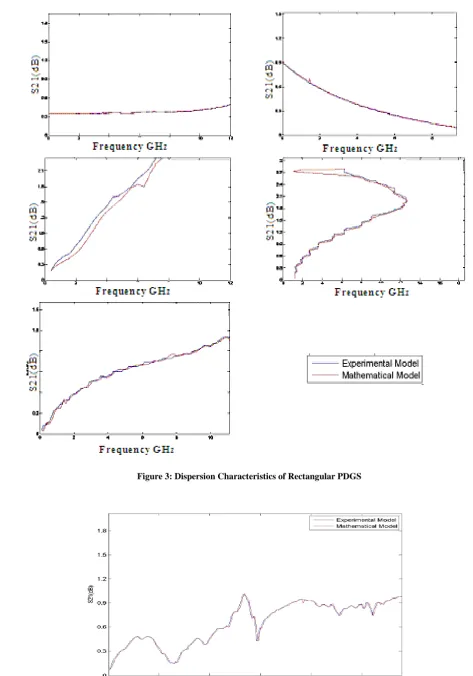
The proposed curve fitting mathematical model is implemented in MATLAB working platform. Then, the dispersion and surface transmission microwave characteristics are chosen for analyzing the proposed model. The analyzed results are compared with experimental model of DGS structure. The analyzed DGS structure are Rectangular, PDGS. From the experimental results of the Rectangular Periodic DGS structure, the curve fitting mathematical model is developed. The propagation characteristics of the curve fitting model are analyzed with the experimental characteristics. Then, from the analyzed characteristics, the propagation uncertainty is determined. After that, the error deviation improvement of the proposed model is evaluated. The dispersion and surface transmission of microwave of rectangular PDGS are described as follows.
4.1. Rectangular PDGS:
Figure 3: Dispersion Characteristics of Rectangular PDGS
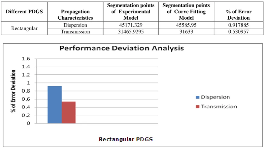
Then, the propagation errors of the proposed curve fitting model are compared with the experimental model. The propagation errors deviation is determined in terms of percentage. The experimental results of error deviation from curve fitting model are described in table I. The performance deviation of percentage of propagation deviation is illustrated
in Fig.5. The formula is used for determining the percentage of error deviation is described as following them
In Fig.5, the dispersion and surface transmission characteristics errors of periodic structures is analyzed for both mathematical model and experimental model. Then, the percentage of error deviation of the proposed model is determined from the experimental model. The error deviation of different periodic structure is plotted in bar chart. From the performance of error deviation, it is clear that the proposed curve fitting mathematical model error is reduced remarkably. So, the proposed mathematical model based periodic structure characteristics analysis is better than the experimental model. Because, the proposed model characteristics analysis helps to design an accurate periodic structure and also reduces the propagation uncertainty.
5. CONCLUSION
In this paper, a curve fitting mathematical model was proposed for analyzing the propagation uncertainty of microwave antenna. For analyzing the propagation uncertainty (error), the proposed model results were compared with the experimental model. Here, the rectangular, dumbbell, and cross dumbbell DGS structures were used for analyzing the propagation characteristics. The DGS structure dispersion and surface wave transmission characteristics were considered for evaluating the performance of the proposed model.
The bounded, leaky and brillouin wave zone boundary were chosen for analyzing the dispersion wave attenuation. From the error deviation, it was clear that the error of the proposed curve fitting model was deviated than the experimental model. Thus, the proposed curve fitting model was more efficient in determining the accurate size of DGS. In future, more DGS
structure will be considered for analyzing the performance of proposed curve fitting model.
6. REFERENCE
[1] J. Chen, Z.B. Weng, Y.C. Jiao and F.S. Zhang, "Lowpass Filter Design of Hilbert Curve Ring Defected Ground Structure", Progress In Electromagnetics Research, Vol.70, pp.269-280, 2007
[2] R. Sharma, T. Chakravarty, S. Bhooshan and A. B. Bhattacharyya, "Design of a Novel 3dB Microstrip Backward Wave Coupler Using Defected Ground Structure", Progress In Electromagnetics Research, Vol.65, pp.261-273, 2006
[3] X. Q. Chen, R. Li, S. J. Shi, Q. Wang, L. Xu and X. W. Shi, "A Novel Low Pass Filter Using Elliptic Shape Defected Ground Structure", Progress In Electromagnetics Research, Vol.9, pp.117-126, 2008
[4] L. H. Weng, Y. C. Guo, X. W. Shi and X. Q. Chen, "An Overview on Defected Ground Structure", Progress In Electromagnetics Research, Vol.7, pp.173-189, 2008
[5] S. H. Zainud-Deen, M. E. Badr, E. El-Deen, K. H. Awadalla and H. A. Sharshar, "Microstrip Antenna With Defected Ground Plane Structure as a Sensor For
Model Fitting Curve
Model al Experiment Model
Fitting Curve Deviation Error
of
[image:6.595.68.531.194.439.2]%
Table I: Segmentation Points of Different PDGS and the Error Deviation.
Different PDGS Propagation
Characteristics
Segmentation points of Experimental
Model
Segmentation points of Curve Fitting
Model
% of Error Deviation
Rectangular Dispersion 45171.329 45585.95 0.917885
Transmission 31465.9295 31633 0.530957
Landmines Detection", Progress In Electromagnetics Research, Vol.4, No.4, pp.27-39, 2008
[6] H. Liu, Z. Li and X. Sun, "Compact Defected Ground Structure in Microstrip Technology", Electronics Letters, Vol.41, No.3, pp.132-134, 2005
[7] H. Oraizi and M. S. Esfahlan, "Miniaturization of Wilkinson Power Dividers by Using Defected Ground Structures", Progress In Electromagnetics Research Letters, Vol.4, pp.113-120, 2008
[8] X. Q. Chen, L. H. Weng, Y. C. Guo and X. W. Shi, "RF Circuit Design Integrated with Microstrip DGS", Progress In Electromagnetics Research, Vol.3, pp.141-152, 2008
[9] M. Naghshvarian Jahromi and M. Tayarani, "Miniature Planar UWB Bandpass Filters with Circular Slots in Ground", Progress In Electromagnetics Research Letters, Vol.3, pp.87-93, 2008
[10]S. A. Hosseini, Z. Atlasbaf and K. Forooraghi, "Two New Loaded Compact Planar Ultra-Wideband Antennas Using Defected Ground Structures", Progress In Electromagnetics Research, Vol.2, pp.165-176, 2008
[11]J. P. Geng, J. J. Li, R. H. Jin, S. Ye, X. L. Liang and M. Z. Li, "The Development of Curved Microstrip Antenna with Defected Ground Structure", Progress In Electromagnetics Research, Vol.98, pp.53-73, 2009 [12]F. J. Wang and J. S. Zhang, "Wide Band Cavity-Backed
Patch Antenna for PCS/IMI2000/2.4GHZ WLAN", Progress In Electromagnetics Research, Vol.74, pp.39-46, 2007
[13]Arya, Ashwini K.Kartikeyan and M.V.Patnaik, "Defected Ground Structure in the perspective of Microstrip Antennas: A Review", Journal of RF-Engineering and Telecommunications, Vol.64, No.5-6, pp.79-84, 2010
[14]M.F. Karim, A.-Q. Liu, A. Alphones, X.J. Zhang and A.B. Yu, "CPW band-stop filter using unloaded and loaded EBG structures", IEE Proceedings on Microwaves, Antennas and Propagation, pp.434-440, 2005
[15]Heeduck Chae, Jong-Sik Lim, Cheol-Sig Pyo, Soon-Ick Jeon, Ji-Hoon Bae and Sangwook Nam, "Analysis of Periodically Loaded Defected Ground Structure and Application to Leaky Wave Antennas", Asia-Pacific Microwave Conference, 2003
[16]A. M. Attiya, "Dyadic Green’s Function of an Elementary Point Source Above a Periodically-Defected-Grounded Dielectric Slab", Progress In Electromagnetics Research, Vol.4, pp.127-145, 2008
[17]S.C. Zhao, B.Z. Wang and Q.Q. He, "Broadband Radar Cross Section Reduction of a Rectangular Patch Antenna", Progress In Electromagnetics Research, Vol.79, pp.263-275, 2008
[18]Jong-Sik Lim, Ho-Sup Kim, Jun-Seok Park, Dal Ahn and Sangwook Nam, "A Power Amplifier with Efficiency Improved Using Defected Ground Structure", IEEE Microwave and Wireless Components Letters, Vol.11, No.4, pp.170-172, April 2001
[19]Hai-Wen Liu, Zheng-Fan Li, Xiao-Wei Sun and Jun-Fa Mao, "An Improved 1-D Periodic Defected Ground Structure for Microstrip Line", IEEE Microwave and Wireless Components Letters, Vol.14, No.4, pp.180-182, April 2004
[20]X. Q. Chen, X. W. Shi, Y. C. Guo and C. M. Xiao, "A Novel Dual Band Transmitter Using Microstrip Defected Ground Structure", Progress In Electromagnetics Research, Vol.83, pp.1-11, 2008
[21]Susanta Kumar Parui and Santanu Das, "Modeling of Split-ring Type Defected Ground Structure and Its Filtering Applications", Journal of Microwaves, Optoelectronics and Electromagnetic Applications, Vol.8, No.1, pp.6-12, June 2009
[22]J. X. Liu, W. Y. Yin and S. L. He, "A New Defected Ground Structure and its Application For Miniaturized Switchable Antenna", Progress In Electromagnetics Research, Vol.107, pp.115-128, 2010
[23]Yuchun Guo and Qing Wang, "An Improved Parameters Extraction Method for Dumbbell-Shaped Defected Ground Structure", Vol.2, No.3, pp.197-200, March 2010
[24]Mouloud Challal, Arab Azrar and Mokrane Dehmas, "Rectangular Patch Antenna Performances Improvement Employing Slotted Rectangular shaped for WLAN Applications", IJCSI International Journal of Computer Science Issues, Vol.8, No.1, pp.254-258, May 2011
[25]Tamasi Moyra, Susanta Kumar Parui and Santanu Das, "Design of a Quasi- elliptic Lowpass Filter using A New Defected Ground Structure and Capacitively Loaded Microstrip Line", International Journal on Electrical Engineering and Informatics, Vol.3, No1, pp.61-73, 2011