© 2019, IRJET | Impact Factor value: 7.211 | ISO 9001:2008 Certified Journal | Page 2149
DESIGN AND IMPLEMENTATION OF FREE SPACE OPTICS
Priyansh Verma
1, Rishabh Chahal
2, Paras Singh
3, Robin Kumar
41,2,3,4
Student, Dept. of Electronics and Communication Engineering, IMS Engineering College, Adhyatmik Nagar,
Ghaziabad, Uttar Pradesh, India
---***---Abstract –
There are different ways to create acommunication between two devices. Whether it is a wired communication network or a wireless communication network, both these type of network have their own advantages in their own field. In wireless communication, Free Space Optics is an optical communication technology which uses light propagating in free space to wirelessly transmit the data from one place to another or we can say that from source to destination. The main aim of working on this project is the proper use of the unlicensed band in creating wireless communication which makes this project less costly. This project is an alternative to optical fiber communication. If this technology come under consideration in the future with further developments, it is possible that this technology will replace electromagnetic wave communication. In this, we have used audio/voice signal as the message (input) signal which is amplified and transmitted through LED/LASER and is received by a solar cell/photodetector respectively. The received electrical signal is further amplified and converted into audio/voice with the help of the speaker.
Key Words: Free Space Optics, Line of Sight, IC-LM386, LED, Solar Cell.
1. INTRODUCTION
Free space optics (FSO) is a wireless communication technology in which the line of sight technology is used. It can work over distances of several hundred meters to a few kilometres. Free-space-optical links can be implemented using laser/LEDs as a source and the receiver with photodetector/solar cell at the receiver end. The use of a laser is a simple concept similar to the one used in optical transmissions using fiber-optic cables; the only difference is the medium. As we know that light travels faster in air than it does through glass, so it is fair to classify FSO as optical communications at the speed of light. Use of laser in communication systems is the future because of the advantages of the full channel speed, no communication license required at present, compatibility with copper or fiber interfaces and no bridge or router requirements.
In this type of technology, voice, video, and data are sent through the air (free space) on low-power light beams at speeds of megabytes or even gigabytes per second. A free-space optical link consists of two optical transceivers which are accurately aligned to each other with a clear
[image:1.595.312.560.258.393.2]line-of-sight. Generally, the optical transceivers can be mounted on building rooftops as shown in fig-1. These transceivers consist of a laser transmitter or an LED with a convex lens and a detector (photodetector or solar cell) to provide the full duplex capability.
Fig -1: A Typical FSO Setup
2. FSO VS RF (Radio Frequency)
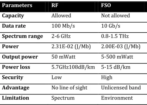
Table -1: FSO VS RF
Parameters RF FSO
Capacity Allowed Not allowed
Data rate 100 Mb/s 10 Gb/s
Spectrum range 2-6 GHz 0.8-1.5 THz
Power 2.31E-02 (J/Mb) 2.00E-03 (J/Mb)
Output power 50 mWatt 5-500 mWatt
Power loss 5.7GHz108dB/km 5-15 dB/km
Security Low High
Advantage No line of sight Unlicensed band
Limitation Spectrum Environment
The data rate in FSO is nearly 100 times better than RF that means through FSO we can transmit high-quality multimedia, data in a short period of time.
The power required in FSO is less in comparison to RF. The output power in FSO can be achieved up to 500mWatt whereas in RF it is of about 50 mWatt.
[image:1.595.305.564.465.650.2]© 2019, IRJET | Impact Factor value: 7.211 | ISO 9001:2008 Certified Journal | Page 2150
The transmission of data in FSO is secure whereas in RF it is not that much secure.
The only limitation that FSO has is that it depends on the environmental conditions whereas RF does not.
3. BLOCK DIAGRAM
Transmitter
Receiver
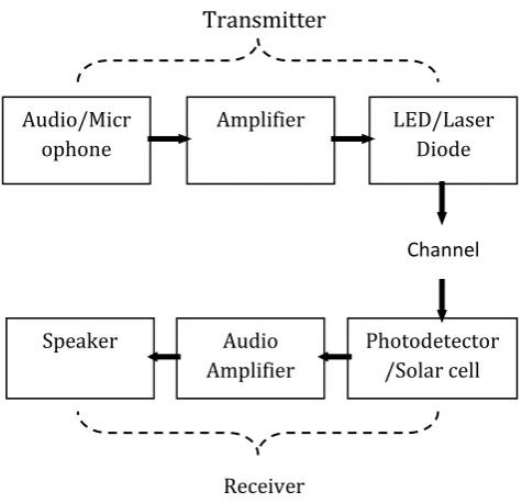
The block diagram of FSO is shown above. It can be divided into two parts – transmitter and receiver.
In the transmitter, the input audio signal is given via 3.5mm jack to the amplifier. We can also use a condenser microphone that converts voice signal into an electrical signal. This electrical signal is then amplified with the help of an amplifier and is passed through an LED/LASER that converts the amplified electrical signal into an optical signal. This optical signal that carries our input message is then transmitted in free space (channel).
In the receiver, the received optical signal is detected with the help of solar cell/photodetector. The detected optical signal is converted into an electrical signal by the solar cell/photodetector and is further amplified by using an audio amplifier before being fed into the speaker. In the end, the speaker is used to convert the electrical signal back into the audio signal.
4. COMPONENTS REQUIRED
The various components that will be required to make the transmitter and receiver are listed below.
a. IC- LM386
b. Capacitors- Electrolyte, Ceramic
c. Resistors
d. Potentiometer
e. Condenser microphone
f. 3.5mm audio jack
g. 9V Battery
h. White LED/Laser diode
i. Solar cell/Photodetector
j. Speaker
4.1 IC-LM386
[image:2.595.41.279.173.402.2]The LM386-IC is a low power audio frequency amplifier which requires a low-level power supply (most often batteries). It comes in an 8-pin mini-DIP package. It is designed to deliver a voltage amplification of 20 without external add-on parts. But this voltage gain can be raised up to 200 (Vu = 200) by connecting a wire between pin 1 and 8.
[image:2.595.331.531.272.637.2]Fig -2: IC-LM386
Fig -3: IC-LM386 Pin Configuration
4.2 Capacitors
There are two types of capacitors which we have used are-
a. Electrolyte
b. Ceramic
Audio/Micr ophone
Amplifier LED/Laser
Diode
Photodetector /Solar cell Audio
Amplifier Speaker
© 2019, IRJET | Impact Factor value: 7.211 | ISO 9001:2008 Certified Journal | Page 2151
Fig -4: Electrolytic capacitorFig -5: Ceramic capacitor
4.3 Laser Diode
[image:3.595.347.506.187.355.2]A Laser Diode is a semiconductor device similar to a light-emitting diode (LED). It uses p-n junction to emit coherent light in which all the waves are at the same frequency and phase. This coherent light is produced by the laser diode using a process termed as "Light Amplification by Stimulated Emission of Radiation", which is abbreviated as LASER. And since a p-n junction is used to produce laser light, this device is named as a laser diode.
Fig -6: Laser Diode
4.4 Condenser Microphone
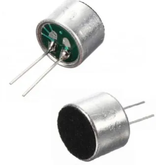
A condenser microphone is a transducer that converts sound into an electrical signal. It consists of a vibrating diaphragm that works as a capacitor plate and the piezoelectric microphone. The piezoelectric microphone uses a crystal of piezoelectric material.
Fig -7: Condenser Microphone
4.5 Photodetector
[image:3.595.344.525.485.616.2]Photodetectors are used primarily as an optical receiver to convert light into electricity. A photodetector operates by converting light signals that hit the junction into a current. The junction uses an illumination window with an anti-reflect coating to absorb the light photons.
Fig -8: Photodetector
4.6 Solar Cell
[image:3.595.48.276.575.724.2]© 2019, IRJET | Impact Factor value: 7.211 | ISO 9001:2008 Certified Journal | Page 2152
Fig -9: Solar Cell [image:4.595.306.563.150.363.2]5. CIRCUIT DIAGRAM
Fig -10: Transmitter Circuit
Fig -11: Receiver Circuit
6. ANOTHER MODEL
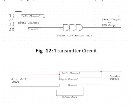
We have worked on another model to transmit the audio signal from source to destination.
This model comprises less number of components as compared to the one explained above.
As it has less number of components, so this model is cost-effective in nature and easy to make.
In this model, a 3.5mm jack is used by which the input audio signal from a cell phone is given to the laser diode/LED. The light from the laser diode/LED is then incident on a solar cell whose output is given to the speaker (any speaker with a 3.5mm aux input).
Fig -12: Transmitter Circuit
Fig -13: Receiver Circuit
7. ADVANTAGES
a. Rapid Deployment: Free space optics enables very fast deployment of broadband access services. Installation of FSO is very easy and it takes less than 1 hour to install at normal working locations.
b. Cost Effective: FSO has compelling economic advantages. Free space optics systems require very low initial investments as compared to fiber optic communication systems.
c. Disaster Management: Optical fiber cable can be destroyed during natural disasters whereas FSO system can be used to quickly restore the network.
d. Last-mile Network Solutions: These are the links that reach the end user. Free Space Optics can be installed in point, point-to-multipoint, ring or mesh connections.
[image:4.595.38.290.314.641.2]© 2019, IRJET | Impact Factor value: 7.211 | ISO 9001:2008 Certified Journal | Page 2153
f. High Speed: Transmission of data can be done at a very high speed as compared to the electromagnetic wave.
8. CONCLUSION
All the research in this paper is based on how we can transfer the data from a source to a destination wirelessly via laser/LED. The technology of wireless communication is increasing day by day. Whether it is radio wave, microwave or optical fiber communication, all these types of communication systems have their own advantages and disadvantages in their own field and are being successfully used presently for the transmission of data. Undoubtedly, FSO is the future of optical communication. There are some cases where optical fiber communication cannot work efficiently and that can be fulfilled by FSO as it is cheaper and the construction of the transmitter and receiver of FSO is simple. It is increasingly finding its way into a range of enterprises and service providers’ application. As the need for high-speed communication is growing, service providers are looking for reasonable bandwidths to deliver excellent services. FSO is easy and quick to install and provide very high-speed data rate. This allows service providers to acquire more customers in comparison to the optical fiber. FSO continues to accelerate the vision of all-optical network cost-effectively, reliably and quickly with freedom and flexibility of
deployment. Although FSO is superior in many fields, it
mostly depends on the external environmental factors. But with the help of advance, powerful lasers and research in the field of FSO can help to overcome this problem.
REFERENCES
[1] “Laser and its applications,” Popular Science &
Technology Series, DRDO Publications, 2009.
[2] Sedra, Adel.S and Smith, Kenneth C, “Microelectronic
Circuits”, Oxford University Press, 1998.
[3] O.Bishop, “Electronics Circuits and Systems”, 4th ed.
Oxford, U.K, Newnes, 2011, pp. 14.
[4]
https://en.wikipedia.org/wiki/Free-space_optical_communication
[5]
https://www.cablefree.net/wirelesstechnology/free-space-optics/history-of-free-space-optics/
[6] https://www.digitalairwireless.com/articles/blog/fre
e-space-optics
[7]
https://www.electroschematics.com/552/lm386-audio-amplifier/
[8]
https://www.electronicshub.org/laser-diode-working-structure-types-uses/
[9] https://www.britannica.com/technology/solar-cell
[10]
https://www.edgefx.in/lm386-audio-amplifier-circuit/
[11]
https://www.instructables.com/id/Laser-Audio-Transceiver/
[12]