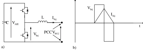
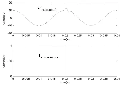
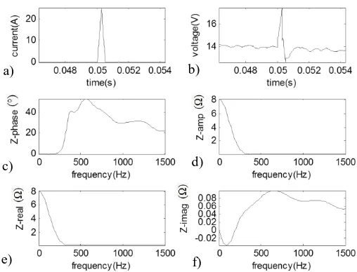
Marine power distribution system fault location using a portable injection unit
Full text
Figure
Related documents
We present the first version of OMEN-SED (Organic Matter ENabled SEDiment model), a new, one- dimensional analytical early diagenetic model resolving or- ganic matter cycling and
Hindawi Publishing Corporation EURASIP Journal on Wireless Communications and Networking Volume 2006, Article ID 25861, Pages 1?13 DOI 10 1155/WCN/2006/25861 Multiservice Vertical
The lake threshold for Gällsboträsket was measured using the RTK technique, while the rest of the brook was measured with the total station (Figure 5-3). The brook furrow is clearly
Drawing on study findings, I propose a series of guidelines for developing microfinance programs that promote not just Tanzanian women’s economic livelihood, but also more
This study was carried out to describe the outcome in patients of traumatic brain injury after road traffic crash in our local setting and provide baseline data for
sativa oil (NSO) proved its great therapeutic potential of NSO in inhibiting the development of tramadol (an opioid drug) dependence and tolerance in mice.. After repeated
Different graphite samples were studied under transmitted and reflected light microscope to decipher the texture, structures and macrostructures of graphite , associated
In attendance were Joe Perez, Roberto & Lucila Flores, Tito Fernandez, James & Elizabeth Salinas, Larry and Yolanda Kirkpatrick, Priscilla Marrah, Joseph Mannix,
