Colocalised Raman and force spectroscopy reveal the roles of hydrogen bonds and
-interactions in defining the mechanical properties of diphenylalanine nano- and
micro-tubes
Faris Sinjab, Georgi Bondakov, and Ioan Notingher
Citation: Applied Physics Letters 104, 251905 (2014); doi: 10.1063/1.4885090 View online: http://dx.doi.org/10.1063/1.4885090
View Table of Contents: http://scitation.aip.org/content/aip/journal/apl/104/25?ver=pdfcov Published by the AIP Publishing
Articles you may be interested in
The bonding, charge distribution, spin ordering, optical, and elastic properties of four MAX phases Cr2AX (A=Al or Ge, X=C or N): From density functional theory study
J. Appl. Phys. 114, 183503 (2013); 10.1063/1.4829485
Direct measurement of bending stiffness and estimation of Young's modulus of vertically aligned carbon nanofibers
J. Appl. Phys. 113, 194308 (2013); 10.1063/1.4803853
Determination of the elastic properties of SiO2 nanotubes templated from organic amphiphilic self-assemblies through inorganic transcription
Appl. Phys. Lett. 102, 151904 (2013); 10.1063/1.4801760
Combined quantitative ultrasonic and time-resolved interaction force AFM imaging Rev. Sci. Instrum. 82, 013703 (2011); 10.1063/1.3514099
Co-localised Raman and force spectroscopy reveal the roles of hydrogen
bonds and
p
-
p
interactions in defining the mechanical properties of
diphenylalanine nano- and micro-tubes
Faris Sinjab, Georgi Bondakov, and Ioan Notinghera)
School of Physics and Astronomy, University of Nottingham, Nottingham, United Kingdom
(Received 7 April 2014; accepted 13 June 2014; published online 24 June 2014)
An integrated atomic force and polarized Raman microscope were used to measure the elastic properties of individual diphenylalanine (FF) nano- and micro-tubes and to obtain quantitative in-formation regarding the inter-molecular interactions that define their mechanical properties. For individual tubes, co-localised force spectroscopy and Raman spectroscopy measurements allowed the calculation of the Young’s and shear moduli (2565 GPa and 0.2860.05 GPa, respectively) and the contribution of hydrogen bonding network to the Young’s modulus (!17.6 GPa). Thep-p interactions between the phenyl rings, dominated by T-type arrangements, were estimated based on previously published X-ray data to only 0.20 GPa. These results provide experimental evidence obtained from individual FF tubes that the network of H-bonds dominates the elastic properties of the FF tubes.VC 2014 AIP Publishing LLC. [http://dx.doi.org/10.1063/1.4885090]
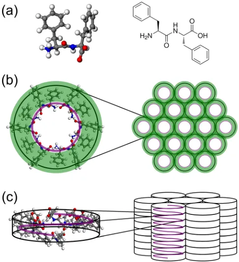
Self-assembled amyloid-like structures have unique physical and chemical properties, providing opportunities for engineering nano- and micro-scale biomaterials.1,2The for-mation of fibrils has also been associated with numerous pathologic conditions such as Alzheimer’s and Creutzfeldt-Jacob diseases.3–5 The diphenylalanine (FF) (L-Phe-L-Phe) peptide is the core recognition motif for self-assembly of the b-amyloid peptide associated with Alzheimer’s disease.6 This peptide has been used as a building block for fabrication of nano- and micro-tubular structures (Fig.1) that have been proposed for biosensing, bioimaging, drug delivery applica-tions, as well as for 3D tissue culture scaffolds.7 Previous studies showed that the elastic moduli of protein fibrils vary over four orders of magnitude.8 For some amyloid fibrils, values of the Young’s moduli as high as 13 GPa have been measured.8Theoretical models indicated that the back-bone interactions, which are dominated by the hydrogen-bonding network and modulated by side-chain interaction, were cru-cial in stabilizing the structure of the fibrils and defining their high rigidity.8 Similarly, the high density of H bonds between the nanoscale crystalline monomers in silkworm and spider silks was shown to provide high elastic moduli, similar to amyloid-fibrils.9
The mechanical properties of FF tubular structures have been measured by atomic force microscopy (AFM) indenta-tion measurements and bending beam models.10,11The values for the Young’s moduli from these studies were reported to be 19 GPa (Ref.10) and 2764 GPa,11and shear modulus of 0.1560.02 GPa.11 Recent density functional theory studies described the structure of the FF fibrils in terms of an array of peptide nanotube backbones with interpenetrating “zipper-like” aromatic interlocks. It was suggested that the Young’s modulus in the longitudinal direction had a dominant contri-bution from the H bonds linking the peptide backbones, while dispersive interactions, mostly p-p interactions, had a
contribution higher than!50% to the Young modulus in the directional perpendicular to the tube axis (!8.8 GPa).12
[image:2.612.316.559.414.681.2]In this study, an integrated atomic force-Raman micro-scope was used to perform co-localised force spectroscopy and polarised Raman micro-spectroscopy (PRMS) measure-ments on individual FF nano- and micro-tubes. Such a setup allows measurement of the Young’s and shear modulus by the bending beam method described and co-localised
FIG. 1. Schematic description of the diphenylalanine (FF) porous tubular structures. (a) FF building block; (b) cross-section of the porous FF tubes showing the peptide cylinders connected by the phenyl rings; (c) FF cylin-ders formed by the peptide backbones. In (b) and (c), the peptide backbone is highlighted by a purple line, and the side chain (phenyls) denoted by a green annulus.
a)Electronic mail: [email protected]
polarized Raman spectra that reveal the molecular structure, orientations, and force constants for particular vibrational modes. Therefore, the Young’s modulus and the contribu-tions from the hydrogen bonded to the mechanical strength can be measured experimentally on individual FF tubes.
All peptide solutions were prepared by initially solubilis-ing lyophilised L-diphenylalanine (FF) peptide (Sigma Aldrich) in 1,1,1,3,3,3-hexafluoro-2-propanol (HFIP) (Sigma Aldrich) to give a stock solution of 100 mg/ml. Stock solu-tions were further diluted to a working concentration of 2 mg/ ml using ultrapure water (pH 6, resistivity 18.2 MX cm). Copper transmission electron microscope (TEM) grids with window size of 19"19 lm (G1000HS, Gilder grids, UK), which have empty windows, were utilized as a support for the tubes. Using a pair of tweezers, the TEM grids were pulled gently through a solution of FF tubes so that tubes attached on one side. Immediately after this, the grids were deposited onto a quartz microscope slide (SPI supplies) and air-dried.
All measurements were performed using an in-house polarized Raman micro-spectrometer and integrated atomic force microscope (NanoWizard II, JPK).13 The instrument allows for co-localised force spectroscopy and polarised Raman spectroscopy measurements for individual FF tubes. Each AFM tip (AC240TS, Asylum) was calibrated for the sensitivity [nm/V] by acquiring a force curve from a clean glass coverslip and linearly fitting the contact region. The spring contact of the cantilever [N/m] was subsequently determined by fitting a Lorentzian curve to the thermal reso-nance of the tip away from a surface. This calibration allows the voltage setpoint for the AFM to be converted to an equiv-alent force setpoint. The polarised Raman spectra were recorded using a similar experimental setup and methods as reported previously.14 The Raman spectra were recorded while force measurements were performed—during which the tip was kept at the corresponding force setpoint value for 50 s, while the Raman spectra were recorded for 45 s within this time window.
The Young’s and shear moduli of a single tube can be determined by pressing sections of a tube at the half-way point of the suspended lengthL11
1
Eb¼ 1
Eþ
48fSIS
GA
1
L2; (1)
whereEandGare the Young’s and shear moduli of the tube, respectively,fsis the form factor of the tube,Isis the second
moment of area, A is the cross-sectional area, andL is the suspended length. The termEbis the bending modulus and is
written in terms of the force applied by the AFM tip, and the deflection as
1
Eb¼ 192dIS
FL3: (2)
For each section of a suspended tube, an AFM image was acquired in order to measure L and the diameter D
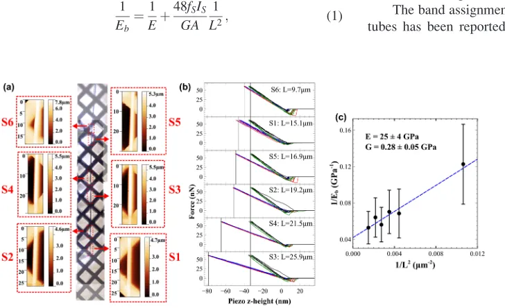
(which will then giveIS). The deflectiondwas obtained by finding the difference in the piezo-stage z-position for the same force setpoint (60 nN) between measurements on and away from the midpoint of the suspended tube, as seen in Fig. 2(b). Effects due to deformation and indentation have been excluded, as these been shown to occur only at suffi-ciently elevated temperatures.15
Prior to obtaining co-localised force spectroscopy and Raman spectroscopy data from individual FF tubes, the elas-tic moduli of four FF tubes (two of which have diameter larger than 1500 nm, and two have diameter of roughly 800 nm) were measured using the bending beam model to es-tablish the accuracy of this method (Fig. 2). For each tube, the values ofEandGwere calculated by linearly fitting the results shown in Fig. 2(b). The force spectroscopy results indicate that the Young’s and shear moduli for this particular FF nanotube are 2564 GPa and 0.2860.05 GPa, in agree-ment with previous reports.11The elastic moduli for the FF tubes are significantly higher than for other cross-bamyloid structures investigated previously (2–14 GPa).8
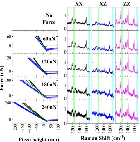
To provide insight into the contributions of the H bond-ing network and side-chain interactions to the elastic moduli of the FF tubes, Raman spectra and force spectra were acquired for individual FF tubes. Fig.3shows an example of co-localised AFM force spectra and polarised Raman spec-troscopy measurements for a typical FF tube. After the col-lection of force spectra that allowed calculation of the Young’s modulus, polarised Raman spectra were acquired from the same FF tubes while using the AFM tip to apply forces in the range of 0–240 nN.
[image:3.612.50.414.550.772.2]The band assignment for the Raman spectra of FF nano-tubes has been reported earlier based on experimental and
FIG. 2. Typical example of using the bending beam model to measure the Young’s and shear moduli of FF tubes. (a) Composite micrograph showing the length of a single isolated tube on a copper grid, with accompanying AFM images for six suspended sections of
differing lengthsL. (b) Force spectra
measured at different sections (blue-extend, red-retract), and at the fixed end of the tube (black-extend,
blue-retract). (c) Plot of 1/Ebversus 1/L2for
the measurement of the Young’s and
shear moduli using Eq.(1).
density functional theory.14 In particular, the 1249 cm%1 Raman band was assigned to the amide III band, which cor-responds to the combination of C-N stretching and N-H in-plane bendings.14,16,17 The polarization dependence of the amide III band is noticeable in Fig.3as the intensity in the XX configuration is higher than in the ZZ configuration, indicating that the principal axis of the Raman tensor of the amide III vibration is oriented perpendicular to the axis of the nanotubes (the first index denotes the laser polarization and the second index represents the direction of the analyzer, while the excitation laser and the Raman back-scattered radi-ation propagated in the Y direction). The frequency of the amide III band depends on the properties of the backbone, peptide bond, and conformation of peptides (Ramachandran angles) as well as hydrogen bonding at the N-H and C¼O. Theoretical studies have showed that hydrogen bonding at N-H site can increase the vibration frequency of the amide III band by!22 cm%1.18
Experimental evidence of blue-shifting of the amide III band upon H bonding at the N-H site has been reported, both for a-helical and b-sheet polypeptides.19 In addition, com-parison between experimental and theoretical calculations of the Raman spectra of polypeptides allowed the estimation of the force constants corresponding to H bonds based on the frequency of the amide III band.20–22 Theoretical calcula-tions showed that forb-sheet polypeptides, such asb-(Ala)n
strong H bonds (N-H…O angle !165&, H…O distance
!1.76 A˚ ) led to amide III band at!1243 cm%1, which corre-sponds to a force constant of 15 N/m.21,22On the other hand, a lower frequency of the amide III band in the Raman spec-trum ofb-(GlyI)n(1234 cm%1) was correlated with weaker H
bonding (N-H…O angle !134&, H…O distance !2.12 A˚ ) and a lower value of the force constant of!12.5 N/m.20FF
tubes have no H bonds at the C¼O sites;14 therefore, the amide III band at 1249 cm%1indicates strong H bonding cor-responding to an estimated force constant of fAm¼15 N/m.
These results agree with the geometrical results obtained from X-ray data for the FF crystals indicating a N-H…O angle of!154&and H…O distance of!1.86 A˚ .12Fig.3also shows that no shifts in the frequency of the amide III were detected in the polarised Raman spectra when forces in the range of 0–240 nN were applied to the FF tubes. These results indicates that bending of the FF tubes led did not change the force constants associated to the H bonding, sug-gesting a strong contribution of the H bonding network to the mechanical properties of the tubes.
Apart from the H bonds associated to the N-H sides of the amide bonds, there are an additional six H bonds per unit cell associated to the head-to-tail interactions NH3þ…–OOC
[image:4.612.314.558.287.710.2](Fig.4). Based on the X-ray data of FF crystals, these bonds are characterised by a!144& N-H…O angle and !1.89 A˚
FIG. 3. Example of performing simultaneously polarized Raman and force spectroscopy measurements on the FF tube for which the elastic moduli
measurements were presented in Fig.2. The direction Z is along the FF tube
[image:4.612.55.296.469.713.2]and the excitation laser and the Raman back-scattered radiation propagated in the Y direction.
FIG. 4. Schematic description of the inter-molecular interactions in porous FF tubes. (a) The network of H bonds provides a strong contribution to the elastic modulus in the longitudinal direction (Z axis). (b) The high-density
of phenyl rings leading top-pinteractions (both T-shaped and parallel
H…O distance,12 suggesting a lower force constant, of
fHT¼13.87 N/m compared to the H bonds corresponding the
amide bonds. Using the values for the force constants for the H bonding, the contribution of the H bonding network in to the Young’s modulus of FF nano- and micro-tubes can cal-culated by using a simple network of springs linking the units cells along the tube axis
EHB¼fAmhfAmþfHThfHT¼17:6 GPa; (3)
whereh¼5.38 A˚ distance between the ring-like structures of six molecules (or the unit cell along the tube axis), and fAm¼fHT¼6/(23"23) A˚%2is the density of the H bonds.
The value of!17.6 GPa for the H bonding contribution is in close agreement to the theoretically estimated value of
!17 GPa attributed to the back-bone H bonding network in cross-b amyloids.8 In addition to H bonding interactions, Fig.4shows that interactions between the phenyl rings can also produce a considerable contribution to the elastic modu-lus in the Z direction. It is known that the benzene dimer can form two distinct stable configurations, commonly termed T-shaped and parallel-offset interactions.23 Fig. 5(b) shows a cross-section of the atomic model for the FF tubes (built using supplementary material from Azuriet al.12), with the phenyl interactions split into green boxes and blue triangles depending on whether they are directly between two back-bone rings, or between three rings, respectively. Fig. 4(b)
shows the arrangement for these sections along the tube axis (hydrogens removed for clarity). The interactions can be viewed as combinations of T-shaped and parallel offset inter-actions in both groups of phenyl rings. The interaction strength can be estimated from the potential curves for ben-zene dimers24and using the fact that there are 12 phenyl side chains in the unit cell, 6 in a green box region and 6 in the blue triangular region. For the T-shaped interactions in the green boxed regions, the equilibrium potential and separation (measured from molecular model12) are %2.1 kcal/mol andhT-green¼5.0 A˚ , respectively. Modelling the interaction
as a harmonic oscillator gives a spring constant of
fT-green¼0.11 N/m. Similarly, for the phenyl rings in the blue
triangular regions, the equilibrium potential and separation are%2.6 kcal/mol andhT-blue¼4.6 A˚ , leading to a force
con-stant offT-blue¼0.17 N/m. For the parallel-offset
configura-tion of the phenyl rings, the energy can be estimated using the potential function reported by McGaugheyet al.,25for a centroid distance measured to behoffset¼5.38 A˚ (similar to
the green and blue boxed regions). This leads to an energy of
%0.4 kcal/mol, which in turn gives a force constant of
foffset¼0.048 N/m. Using these values, the contribution of
thep-pinteractions to the Young’s modulus is
ESC¼ ð6hT%greenfT%greenþ6hT%bluefT%blue
þ12hof f setfof f setÞ=A; (4)
where A¼23.89"23.89 A˚ is the area of the unit cell. From the T-shaped interactions, the Young’s modulus is 0.15 GPa, and the contribution of the parallel offset interactions is 0.05 GPa, providing a total contribution to the Young’s mod-ulus of FF tubes of 0.20 GPa. Knowleset al.8estimated the range of the side-chain contributions to the Young’s modulus
for cross-b amyloid fibrils using a surface-tension model, which resulted in a range of 0.03–0.13 GPa. The value of 0.20 GPa calculated here is significantly higher than the upper limit specified for amyloid fibrils.8
However, this contribution is still almost two orders of magnitude lower than the contributions from the intermolecu-lar H bonding. Nevertheless, the estimated Young’s modulus of 17.8 GPa is significantly lower than the experimentally measured modulus of 25 GPa from the bending beam model. First, neglecting the anisotropy of these materials may cause the bending beam model to give an overestimate of the Young’s modulus. Second, the calculations of the backbone and side-chain interactions may not take into account all aspects of intermolecular interactions contributing to the elas-tic moduli, such as, for example, the residual water molecules inside the pores, which simulations have shown to be stabilizing.26
The integrated atomic force and polarized Raman micro-scope (AFM-PRM) was used to measure the elastic moduli of individual diphenylalanine nano- and micro-tubes and to obtain quantitative information regarding the inter-molecular interactions that define the mechanical properties. Co-localised force spectroscopy and Raman spectroscopy meas-urements allowed the calculation of the Young’s and shear moduli (2565 GPa and 0.2860.05 GPa, respectively) and the contribution of hydrogen bonding network to the Young’s modulus (!17.6 GPa). Thep-pinteractions between the phe-nyl rings have an estimated total contribution to the Young’s modulus of FF tubes of 0.20 GPa. Although this contribution is significantly larger compared to side-chain interactions in other amyloid fibrils, it is clear that the elastic properties of the FF tubes are dominated by the backbone H bond network.
The combination of AFM-force and polarized-Raman spectroscopy in a single instrument allows for quantitative co-localised mechanical and structural measurements on individual FF nanotubes. In principle, this technique could be applied to other nanoscale peptide fibrils for similar meas-urements at the scale of single fibrils.
1T. Aida, E. W. Meijer, and S. I. Stupp,Science
335, 813 (2012).
2I. W. Hamley,Angew. Chem. Int. Ed.
46, 8128 (2007).
3
D. B. Teplow,Amyloid5, 121 (1998).
4
M. Goedert and M. G. Spillantini,Science314, 777 (2006).
5E. D. Roberson and L. Mucke,Science
314, 781 (2006).
6M. Reches and E. Gazit,Science
300, 625 (2003).
7
X. Yan, P. Zhu, and J. Li,Chem. Soc. Rev.39, 1877 (2010).
8
T. P. Knowles, A. W. Fitzpatrick, S. Meehan, H. R. Mott, M. Vendruscolo,
C. M. Dobson, and M. E. Welland,Science318, 1900 (2007).
9S. Keten, Z. Xu, B. Ihle, and M. J. Buehler,Nature Mater.
9, 359 (2010).
10
N. Kol, L. Adler-Abramovich, D. Barlam, R. Z. Shneck, E. Gazit, and I.
Rousso,Nano Lett.5, 1343 (2005).
11L. Niu, X. Chen, S. Allen, and S. J. B. Tendler,Langmuir
23, 7443 (2007).
12I. Azuri, L. Adler-Abramovich, E. Gazit, O. Hod, and L. Kronik,J. Am.
Chem. Soc.136, 963–969 (2014).
13
C. S. Sweetenham, M. Larraona-Puy, and I. Notingher,Appl. Spectrosc.
65, 1387 (2011).
14B. Lekprasert, V. Korolkov, A. Falamas, V. Chis, C. J. Roberts, S. J. B.
Tendler, and I. Notingher,Biomacromolecules13, 2181 (2012).
15
V. L. Sedman, L. Adler-Abramovich, S. Allen, E. Gazit, and S. J. B.
Tendler,J. Am. Chem. Soc.128, 6903 (2006).
16S. A. Asher, A. Ianoul, G. Mix, M. N. Boyden, A. Karnop, M. Diem, and
R. Schweitzer-Stenner,J. Am. Chem. Soc.123, 11775 (2001).
17
A. V. Mikhonin, S. V. Bykov, N. S. Myshakina, and S. A. Asher,J. Phys.
Chem. B110, 1928 (2006).
18
N. S. Myshakina, Z. Ahmed, and S. A. Asher,J. Phys. Chem. B 112,
11873 (2008).
19M. C. Chen and R. C. Lord,J. Am. Chem. Soc.
96, 4750 (1974).
20
W. H. Moore and S. Krimm,Biopolymers15, 2439 (1976).
21W. H. Moore and S. Krimm,Biopolymers
15, 2465 (1976).
22J. F. Rabolt, W. H. Moore, and S. Krimm, Macromolecules
10, 1065
(1977).
23
C. A. Hunter and J. K. M. Sanders, J. Am. Chem. Soc. 112, 5525
(1990).
24M. O. Sinnokrot and C. D. Sherrill, J. Phys. Chem. A
108, 10200
(2004).
25G. B. McGaughey, M. Gagne, and A. K. Rappe,J. Biol. Chem.
273, 15458 (1998).
26C. Guo, Y. Luo, R. Zhou, and G. Wei,ACS Nano