Space Vector Modulated Three-Level Inverters
with a Single Z-Source Network
Abstract – The Z-source inverter is a relatively recent converter topology that exhibits both voltage-buck and voltage-boost capability. The Z-source concept can be applied to all dc-to-ac, ac-to-dc, ac-to-ac, and
dc-to-dc power conversion whether two-level or multilevel. However, multilevel converters offer many benefits for higher power applications. Previous publications have shown the control of a Z-source neutral
point clamped inverter using the carrier based modulation technique. This paper presents the control of a
Z-source neutral point clamped inverter using the space vector modulation technique. This gives a number of benefits, both in terms of implementation and harmonic performance. The adopted approach enables the operation of the Z-source arrangement to be optimised and implemented digitally without introducing
any extra commutations. The proposed techniques are demonstrated both in simulation and through experimental results from a prototype converter.
Keywords – Z-source inverter, Neutral Point Clamped inverter, Space Vector Modulation, buck-boost.
I. INTRODUCTION
ANY industrial applications require higher power converters (inverters) which are now almost exclusively
implemented using one of the multilevel types. Multilevel converters offer many benefits for higher power
applications which include an ability to synthesise voltage waveforms with lower harmonic content than two-level
converters and operation at higher dc voltages using series connection of a basic switching cell of one type or
another [1],[2],[3],[4].
Even though many different multilevel topologies have been proposed, the three most common topologies are
the cascaded inverter [5],[6],[7], the diode clamped inverter [8],[9],[10],[11],[12] and the capacitor clamped
inverter [13],[14],[15]. Among the three, the three-level diode clamped (also known as the Neutral Point Clamped
(NPC)) inverter has become an established topology in medium voltage drives and is arguably the most popular
[16],[17],[18],[19] – certainly for 3-level circuits. However, the NPC inverter is constrained by its inability to
produce an output line-to-line voltage greater than the dc source voltage. For applications where the dc source is
not always constant, such as a fuel cell [20],[21], photovoltaic array [22], and during voltage sags, etc., a dc/dc
operating point to be favourably located [23],[24]. This increases the system complexity and is desirable to
eliminate if possible.
The Z-source inverter [25] topology was proposed to overcome the above limitations in traditional inverters.
The Z-source concept can be applied to all dc-to-ac [26], ac-to-dc [27], ac-to-ac [28],[29],[30],[31] and dc-to-dc
[32],[33] power conversion whether two-level or multilevel. The Z-source concept was extended to the NPC
inverter in [34], where two additional Z-source networks were connected between two isolated dc sources and a
traditional NPC inverter. In spite of its effectiveness in achieving voltage buck-boost conversion, the Z-source
NPC inverter proposed in [34] is expensive because it uses two Z-source networks, two isolated dc sources and
requires a complex modulator for balancing the boosting of each Z-source network. To overcome the cost and
modulator complexity issues, the design and control of an NPC inverter using a single Z-source network was
presented in [35]. The operational analysis and optimal control of the Reduced Element Count (REC) Z-source
NPC inverter was subsequently described in [36].
The REC Z-source NPC inverter is expected to find applications in grid connected Distributed Generation
(DG) systems based on renewable energy sources such as photovoltaic systems, wind turbines and fuel cell stacks
[37]. Two DG systems can be connected to the grid with only one REC Z-source NPC inverter thus reducing the
volume and cost while increasing efficiency and facilitating control. The power quality of current injected to the
grid is improved because of the three-level structure. It can also find use in Adjustable Speed Drive (ASD) systems
in applications such as conveyor belts, fans and water pumps [38].
In [36] the modulation of the REC Z-source NPC inverter was described using the carrier based approach.
However, the Space Vector Modulation (SVM) approach offers better harmonic performance [11] (compared with
carrier-based PWM strategy without zero sequence voltage injection) and can more conveniently handle overall
switching patterns and constraints [39],[40] and it is simple to implement using a DSP [41]. The contribution of
this paper is therefore the development of a modified SVM algorithm for controlling the REC Z-source NPC
inverter. The theoretical development is discussed in detail and simulations as well as experimental results are
used to verify the operation of the circuit and proposed SVM based modulation.
II. REVIEW OF Z-SOURCE CONCEPT
The topology of a Z-source two-level inverter is shown in Fig.1. The only difference between the Z-source
inverter and a traditional Voltage Source Inverter (VSI) is the presence of a Z-source network comprising a
that the output ac voltage fundamental can be controlled to be any value between zero and (theoretically) infinity
regardless of the dc source voltage. Thus, the Z-source inverter is a buck-boost inverter that has a very wide range
of obtainable output voltage. Traditional voltage source inverters cannot provide such features.
C2
L2 C1
E
Vi Qa1
Qa’1
Qb1
Qb’1
Qc1
Qc’1 L1
Va Vb
Vc D
Fig.1. Topology of Z-source two-level inverter
In Fig.1, the level Z-source inverter bridge has 15 permissible switching states unlike the traditional
two-level VSI that has 8. The traditional three-phase VSI has 6 active states when the dc voltage is impressed across
the load and 2 zero states when the load terminals are shorted through either the lower or upper three devices,
respectively. However, the two-level Z-source inverter bridge has 7 extra zero states (termed shoot-through states)
when the load terminals are shorted through both upper and lower devices of any one phase leg (i.e., both devices
are gated ON), any two phase legs, or all three phase legs. These shoot-through states are forbidden in a traditional
VSI for obvious reasons. The Z-source network makes the shoot-through zero states possible, and provides the
means by which boosting operation can be obtained. Critically, any of the shoot-through states can be substituted
for normal zero states without affecting the PWM pattern seen by the load.
Therefore, for a fixed switching cycle, insertion of shoot-through states within the zero intervals with the active
state intervals maintained constant will not alter the normalized volt-second average per switching cycle seen by
the ac load. Instead, with the shoot-through states inserted, the effective inverter dc link voltage Vi can be stepped
up as given in (1) [25, 42]. Consequently, taking also the PWM modulation index M into account, the phase ac
output voltage VX (X є {a, b, c}) can be expressed by (2):
Vi =
E
𝑉𝑋=𝑀𝑉𝑖
√3 = 𝐵{𝑀𝐸/√3} (2)
where TST and T are the shoot-through interval and switching period, B is the boost factor and the term in
parenthesis represents the phase ac output voltage of a traditional VSI. Equations (1) and (2) show that the ac
output voltage of a Z-source inverter can be regulated from zero to the normal maximum by altering M and
maintaining B = 1, or can be boosted above that obtainable with a traditional VSI by choosing B > 1. A similar
analysis can be carried out for the current type Z-source inverter [43]. However, since the focus of this paper is
that of the voltage-type Z-source inverter, the analysis for the current-type Z-source inverter would not be
discussed further due to space limitation.
III. TOPOLOGY OF REC Z-SOURCE NPC INVERTER
A. Extension of the Z-source concept to the NPC inverter
To describe the principle of the REC Z-source NPC inverter shown in Fig. 2, we concentrate initially on the
operation of one phase leg. The operation of each inverter phase leg of a traditional NPC inverter can be
represented by three switching states P, O, and N. Switching state “P” denotes that the upper two switches in a
phase leg are gated ON, “N” indicates that the lower two switches conduct and “O” signifies that the inner two
switches are gated ON.
However, each phase leg of the Z-source NPC inverter has three extra switching states which resemble the
“O” state of the traditional NPC inverter. These extra switching states occur when all the four (4) switches in any
phase leg are gated ON (Full-Shoot-Through (FST)), or the three (3) upper switches in any phase leg are gated
ON (Upper-Shoot-Through (UST)) or the three (3) bottom switches in any phase leg are gated ON
(Lower-Shoot-Through (LST)). These shoot-through states are forbidden in the traditional NPC inverter because they would
cause a short circuit of the DC side capacitors. Again, the Z-source network makes these shoot-through states
permissible and provides the means for boost operation.
B. Circuit analysis
Among the three-level Z-source power converter topologies reported to date, the Z-source NPC inverter
implemented using a single LC impedance network (see Fig.2) is considered to be an optimized topology in terms
source. The middle point O is taken as a reference. By controlling the switches of each phase leg according to the
combinations presented in Table I, each output phase voltage VXO (X є {a, b, c}) has three possibilities: Vi/2, 0
and –Vi/2.
C2
L2
E
C1
E
Vi Qa1
Qa2
Qa’1
Qa’2
Qb1
Qb2
Qb’1
Qb’2
Qc1
Qc2
Qc’1
Qc’2 L1
Va
Vb
Vc D1
D2
Da1
Da2
Db1
Db2
Dc1
Dc2
O(0V)
N P
Vp
Vn
Fig.2. Topology of a REC Z-source NPC inverter
When the REC Z-source NPC inverter is operated without any shoot-through states then Vi is equivalent to 2E.
As noted earlier, with this kind of operation the maximum obtainable output line-to-line voltage cannot exceed
the available dc source voltage (2E).
Therefore to obtain an output line-to-line voltage greater than 2E, shoot-through states are carefully inserted
into selected phase legs to boost the input voltage to Vi > 2E before it is inverted by the NPC circuitry. Thus the
REC Z-source inverter can boost and buck the output line-to-line voltage with a single stage structure. In [36],
two new switching states namely the UST and LST states were identified, in addition to the FST state and the
Non-Shoot-Through (NST) states (P, O and N) that had been reported earlier in [35]. Although operation using
the FST and NST states is possible (termed the FST operating mode), it is generally preferable to use the UST
and LST states in place of the FST states (termed the ULST operating mode).
The ULST operating mode is preferred because it produces an output voltage with enhanced waveform quality.
The simplest FST operating mode requires all four switches in a phase leg (see Table I) to be turned ON. This is
not a minimal loss approach since, for example, switching phase A from +E through FST to 0V would require switches {Qa1,Qa2, Qa’1,Qa’2} changing from {ON,ON,OFF,OFF} through {ON,ON,ON,ON} to
the shoot through path. This requires, for example, synchronization of the turn ON instants of switches Qa1 from
phase A and Qc’2 from phase C at the start of an FST state. Doing so creates a time interval during which switches
{Qa1, Qa2, Qa’1} from phase A and {Qc2, Qc’1, Qc’2} from phase C are gated ON simultaneously to create a
shoot through path [35]. However, the output line-to-line voltage obtained using the minimal loss FST approach
has higher harmonic distortion (compared to the ULST approach) in its output voltage waveform because the
voltage levels produced do not have adjacent level switching [35].
TABLE I
SWITCHING STATES OF AN REC Z-SOURCE NPC INVERTER
Therefore, in this paper the ULST operating mode is used for controlling the REC Z-source NPC inverter.
Fig.3 (a) shows the simplified equivalent circuit for the NST state while Figs.3 (b) and 3(c) show the upper and
lower shoot-through states. Note that there are multiple ways of creating the UST and LST states using different
phases. The choice between these is discussed later. Assuming that the Z-source network is symmetrical (L1 = L2
= L and C1= C2= C), then VL1 = VL2 = VL and VC1 = VC2 = VC and the voltage expressions for the NST state are:
State Type ON Switches ON Diodes VXO
Switching State
Non-Shoot
Through Qx1,Qx2 D1,D2 +Vi/2 P
Non-Shoot
Through Qx2,Qx’1 D1,D2, {Dx1 or Dx2} 0
O
Non-Shoot
Through Qx’1,Qx’2 D1,D2 -Vi/2
N
Full-Shoot
Through Qx1,Qx2, Qx’1,Qx’2 --- 0 FST
Upper-Shoot
Through Qx1,Qx2,Qx’1 Dx2,D1 0 UST
Lower-Shoot
Non-Shoot-Through
𝑉𝐿 = 2𝐸 − 𝑉𝐶 (3)
𝑉𝑃= + 𝑉𝑖
2 𝑉𝑛= − 𝑉𝑖
2 (4)
𝑉𝑖 = 2(𝑉𝐶− 𝐸) (5)
Similarly, the voltage expressions for the UST and LST states are:
Upper Shoot-Through
𝑉𝐿1= 𝐸 (6)
𝑉𝑃= 0 𝑉 𝑉𝑁= 𝐸 − 𝑉𝐶1 (7)
Lower Shoot-Through
𝑉𝐿2= 𝐸 (8)
𝑉𝑃= −𝐸 + 𝑉𝐶2 𝑉𝑁= 0 𝑉 (9)
We denote the duration of the NST, UST and LST states by TN, TU and TL respectively and the switching
period by T. Also, we assume that TU and TL are equal (this is necessary to ensure symmetrical operation) and
denote the total combined upper and lower shoot-through duration by TULST. At steady state the average voltage
across the inductors is zero, therefore averaging the inductor voltage over one switching period we have:
(2𝐸 − 𝑉𝐶) ∗ 𝑇𝑁+ 𝐸 ∗ 𝑇𝑈+ 𝐸 ∗ 𝑇𝐿
𝑇 = 0 (10)
𝑇𝑁+ 𝑇𝑈+ 𝑇𝐿= 𝑇 (11)
Solving for
V
c using (10) and (11), we have:𝑉𝐶 =
2𝐸(1 − 𝑇𝑈𝐿𝑆𝑇/2𝑇)
(1 − 𝑇𝑈𝐿𝑆𝑇/𝑇) (12)
𝑉𝑖_𝑁𝑆𝑇=
2𝐸
(1 − 𝑇𝑈𝐿𝑆𝑇/𝑇) (13)
Similarly, when (12) is substituted into (7) and (9) and noting that 𝑉𝑖= 𝑉𝑃− 𝑉𝑁 , we have the dc-link voltage
during the UST and LST states as:
E
E
Diodes D1 and D2 Conducting L1
Vi Vp
Vn o(0 V) Vd
VC1 VC2 L2 VL2 VL1 D2 D1
Inverter + Load
(a)
E
E
D2 c Diode D1 Conducting Upper Shoot-Through Representation L1 Vi Vp Vn
o(0 V) Vd
VC1 VC2 L2 VL2 VL1 (b) E E L1 Vi Vp Vn o(0 V) Vd
VC1 VC2 L2 VL2 VL1 D2 D1 Lower-Shoot-Through Representation D1 Blocking D2 conducting (c)
Fig.3. Simplified representation of REC Z-source NPC inverter when in (a) non-shoot-through, (b) upper
shoot-through and (c) lower shoot-through states
𝑉𝑖_𝑈𝑆𝑇= 𝑉𝑖_𝐿𝑆𝑇=
𝐸
(1 − 𝑇𝑈𝐿𝑆𝑇/𝑇) (14)
It is noted from (13) and (14) that the higher dc-link voltage is present during the NST states and it is twice the
dc-link voltage available during the UST and LST states, as required. The fundamental peak ac output voltage
VXO (X є {a, b, c}) is given by:
𝑉̂𝑋𝑂 = 𝑀
√3𝑉𝑖_𝑁𝑆𝑇 (15)
𝑉̂𝑋𝑂= ( 1
1 − 𝑇𝑈𝐿𝑆𝑇/𝑇) { 𝑀
√3(2𝐸)} = 𝐵′ { 𝑀
√3(2𝐸)} (16)
where B’ ≥ 1 is the boost factor [44] and all the other symbols have their usual meaning.
IV. MODIFIED SVM OF THE REC Z-SOURCE NPC INVERTER
The space vector diagram of a traditional NPC inverter for sector 1 is shown in Fig.4. The reference vector,
Vref can be expressed as (17).
𝑉𝑟𝑒𝑓(𝑡) = 2
3[𝑉𝑎𝑜(𝑡) + 𝑉𝑏𝑜(𝑡)𝑒𝑗2𝜋 3⁄ + 𝑉𝑐𝑜(𝑡)𝑒𝑗4𝜋 3⁄ ] (17)
Generally, in SVM, the reference vector 𝑉⃗ 𝑟𝑒𝑓 is synthesized with three nearest space vectors, which are selected
based on the triangle in which the reference vector is located at the sampling instant.
Fig.4. Space vector diagram of sector 1 for a three-level inverter
If the reference vector is located in triangle 3, the nearest three vectors are 𝑉⃗ 1 , 𝑉⃗ 7and 𝑉⃗⃗⃗ 13, respectively. Let the
duty ratios of these vectors be denoted by 𝑑1, 𝑑2 and 𝑑3,respectively. The modulation law with a sequence of
the nearest three vectors based on the volts-second product is then as follows:
𝑉⃗ 1∗ 𝑑1+ 𝑉⃗ 7∗ 𝑑2+ 𝑉⃗ 13∗ 𝑑3= 𝑉⃗ 𝑟𝑒𝑓 (18)
𝑑1+ 𝑑2+ 𝑑3= 1 (19)
The voltage vectors 𝑉⃗ 1 , 𝑉⃗ 7 , 𝑉⃗⃗⃗ 13 and 𝑉⃗⃗⃗ 𝑟𝑒𝑓 in Fig.4 can be expressed as:
𝑉⃗ 1= 1
3∗ (2𝐸) (20)
𝑉⃗ 7=√33 𝑒𝑗𝜋 6⁄ ∗ (2𝐸) (21)
𝑉⃗ 13= 2
3∗ (2𝐸) (22)
Substituting (20), (21), (22) and (23) into (18) and solving together with (19), the duty ratios of the three nearest
voltage vectors are given by (24), (25) and (26), where M is the modulation index and
0
/
3
.𝑑1= 2 − 2𝑀 sin(𝜋 3 + 𝜃⁄ ) (24)
𝑑2= 2𝑀 sin 𝜃 (25)
𝑑3= 2𝑀 sin(𝜋 3⁄ − 𝜃) − 1 (26)
A similar procedure is used for calculating the duty ratios of the selected voltage vectors in all the other triangles.
To complete the modulation process, the selected voltage vectors are applied to the output according to a switching
sequence. Ideally, a switching sequence is formed in such a way that a high quality output waveform is obtained
with minimum number of switching transitions [46].
B. Switching Sequence and Insertion of shoot-through states
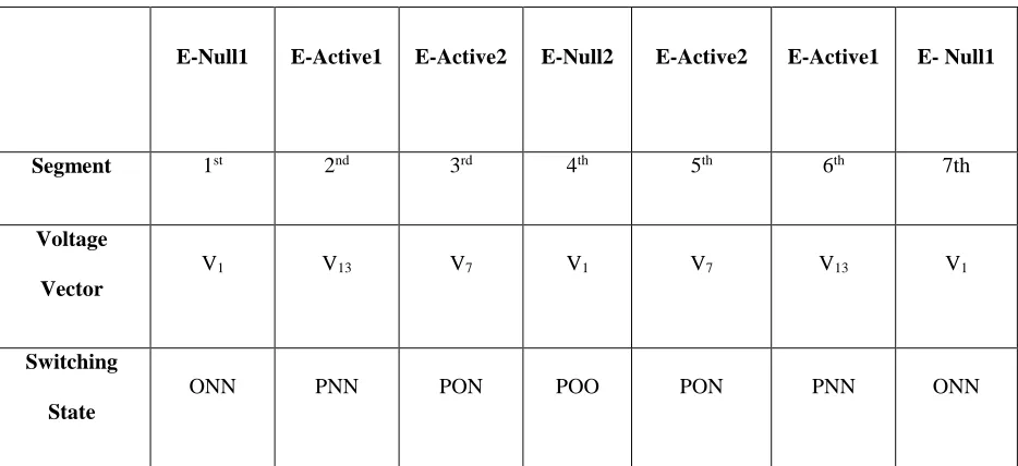
To achieve the minimal number of switches changing between two adjacent states, a seven-segment switching
sequence is adopted in SVM. If the reference vector stays in triangle 3 (see Fig.4), and using the decomposition
method, where the null state is shifted from (PPP/OOO/NNN) to (POO/ONN), the Equivalent Null (E-Null) states
are V1 (POO) and V1 (ONN) while the Equivalent Active (E-Active) states are V7 (PON) and V13 (PNN)
respectively. The seven-segment switching sequence in triangle 3 can then be briefly illustrated as shown in Table
II [46]. In a traditional three-level NPC inverter, only switching transitions between the “P” state and the “O” state
or the “N” state and the “O” state are permitted. Switching directly between the “P” state and the “N” state is not
allowed because it results in all four switches changing state, which results in non-equal dynamic voltage and
double the switching loss.
In order to introduce shoot-through states, it is necessary to determine where the UST and LST states can be
inserted, and on which phase, in order that the normalised volt-second area applied to the load is unchanged from
the standard NPC case discussed above. In addition, it is desirable to ensure that no extra commutations are
introduced. Theoretically, a shoot-through state can be introduced on any phase which is switched to the zero
level (O) without affecting that phase voltage. However, the effect on the line-to-line voltages must also be taken
into account. Note that when any phase has UST applied, the positive rail (P) is at the same potential as the DC
mid-point (O). Similarly, during LST, the negative rail (N) is at the same potential as the DC mid-point (O).
two phases are connected either to O or N in order to get the correct line-to-line voltages. Similarly, a LST state
can only be used when the other two phases are O or P. Therefore, the permissible shoot-through states are as
[image:11.595.66.533.214.428.2]shown in Table III where “U” and “L” represent UST and LST states in a phase leg respectively.
TABLE II
SEVEN SEGMENT SWITCHING SEQUENCE IN TRIANGLE 3
E-Null1 E-Active1 E-Active2 E-Null2 E-Active2 E-Active1 E- Null1
Segment 1st 2nd 3rd 4th 5th 6th 7th
Voltage
Vector
V1 V13 V7 V1 V7 V13 V1
Switching State
ONN PNN PON POO PON PNN ONN
Taking the above into account, the objective is to deploy the UST/LST states for voltage boosting in an optimal
way that does not increase the number of commutations. A modified PWM sequence which achieves this can be
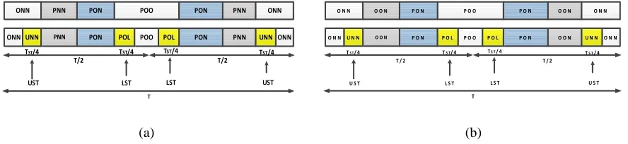
derived as discussed below. Fig.5(a) shows the seven segment PWM switching sequences for modulating a
traditional NPC inverter and a REC Z-source NPC inverter when the reference vector, Vref is in triangle 3 of the
vector diagram shown in Fig.4. Comparing the sequences shown in Fig.5 (a), it is observed that the only difference
between them is the insertion of an UST state in phase A to the left of the E-active state (PNN) and the insertion
of a LST state in phase C to the right of the E-active state (PON), respectively, within half switching period, T/2.
Insertion of shoot-through states at these instants will not result in additional switching since, for example, the
transition from (ONN) to (PNN) can be achieved by switching devices {Qa1,Qa2,Qa’1,Qa’2} from
{OFF,ON,ON,OFF} through {ON,ON,ON,OFF} to {ON,ON,OFF,OFF} [47]. The process is reversed in the
remaining half switching period. The phase A voltage during the UST state is the same as that of the “O” state
0 V (see Fig.3(a)). Hence the (UNN) and (ONN) states can supplement each other for voltage boosting without
modifying the line-to-line volt-second average (normalised by taking the boost factor into account).
TABLE III
PERMISSIBLE SHOOT-THROUGH STATES
UST States LST States
UNN PLO
UON POL
OUN PPL
NUN LPO
NUO OPL
NOU LPP
NNU LOP
UNO OLP
ONU PLP
Applying the same analysis and moving on to the second transition {(PNN) to (PON)}, where phase B switches
from the “N” state to the “O” state, no shoot-through state is inserted (note that it is not possible to introduce UST
or LST for the (PON) state for the reasons discussed earlier). Moving forward again to the third transition {(PON)
to (POO)} where phase C switches from the “N” state to the “O” state, a LST state is inserted since the switching
of devices {Qc1,Qc2,Qc’1,Qc’2} from {OFF,OFF,ON,ON} through {OFF, ON, ON, ON} to
{OFF,ON,ON,OFF} will not affect phases A and B, which remain clamped to points P and O. The phase C voltage during the LST state is equal to that of the “O” state since the voltage E is dropped across inductor L2 and the
voltage seen by phase C is 0 V (see Fig.3 (b)). This means that the (POL) and (POO) states can supplement each
other for voltage boosting without modifying the produced volt-second average (normalised by taking the boost
ONN PNN PON POO PON PNN ONN
ONNUNN PNN PON POL POO POL PON PNN UNN ONN
T/2 T/2
TST/4 TST/4 TST/4
UST LST LST UST
TST/4
T
(a)
O N N O O N P O N P O O P O N O O N O N N
O N N U N N O O N P O N P O L P O O P O L P O N O O N U N N O N N
T / 2 T / 2
TS T/ 4 TS T/ 4 TS T/ 4
U S T L S T L S T U S T
TS T/ 4
T
[image:13.595.81.525.72.174.2](b)
Fig.5. Modulation of Traditional NPC and Z-source NPC when the reference vector is in (a) triangle 3 and (b) triangle 2a on the three-level vector diagram shown in Fig.4
When the previous methodology is applied to another distinct triangle, triangle 2a, a similar state sequence is
derived and shown in Fig.5 (b). It is noted that although it is possible to insert an UST state at the {(OON) to
(PON)} transition, no shoot-though state is inserted at this transition since doing so will result in an inferior output
voltage. From the above, it is noted that in all triangles the UST (or LST) states are inserted at the Null” to
“E-Active” state transitions with no shoot-through states inserted at the “E-“E-Active” to “E-“E-Active” state transitions. It
is also noted that the shoot-through states do not affect the PWM control of the inverter, because they equivalently
produce the same zero voltage at the load terminals. Another feature noted with the ULST modulation scheme is
that the UST and LST states are introduced for only half of the total shoot-through duration of TULST, unlike the
FST modulation scheme, where the Z-source network is shorted for the full shoot-through duration. Therefore, to
produce the same boost factor for the ULST and FST schemes we need to set TULST/T= 2TFST/T, where TFST is
the FST duration. The available shoot-through period is limited by the E-null period that is determined by the
modulation index according to (27) for the simple boost control method [34],[44].
𝑇𝑈𝐿𝑆𝑇
2𝑇 =
𝑇𝐹𝑆𝑇 𝑇 =
𝑇𝑈
𝑇 =
𝑇𝐿
𝑇 = 1 − 𝑀 (27)
Table IV gives a summary of the above discussions when the reference vector is in the various triangles of
sector 1. A similar situation happens in sectors 2 to 6. However, it should be noted that in triangle 1 no
shoot-through states are inserted because this corresponds to a low modulation index which causes the inverter to
degenerate into three-level line-to-line voltage switching with no additional voltage boost produced [34].
TABLE IV
SWITCHING SEQUENCES AND INSERTION OF SHOOT-THROUGH STATES IN TRIANGLES 2 TO 4
2a (ONN)→(UNN)→(OON)→(PON)→(POL)→(POO)
2b (PPO)→(PPL)→(POO)→(PON)→(UON)→(OON)
3 (ONN)→(UNN)→(PNN)→(PON)→(POL)→(POO)
4 (OON)→(UON)→(PON)→(PPN)→(PPL)→(PPO)
V. SIMULATION AND EXPERIMENTAL RESULTS
To verify the proposed approach, simulations were first performed in SABER before the proposed SVM based
modulation algorithm was validated experimentally using a REC Z-source NPC inverter prototype. The hardware
Z-source network was implemented using 6.3mH inductors and 2200uF capacitors, and powered by a 120V split
dc supply. The dc-link output of the Z-source network was connected to an existing NPC inverter to generate the
expected five-level output line-to-line voltage waveform. The Z-source converter was controlled using a Texas
Instrument TI6713 DSK and an Actel ProAsic 3 based FPGA board designed by the University of Nottingham.
A switching frequency of 5 kHz was used for this study.
A. Simulation Results
In the SABER simulation platform a standalone RL load comprising a three-phase 57.6 Ω resistor bank and a
three-phase 35.5mH inductor bank was used to verify the theoretical findings. To demonstrate the boosting ability
of the REC Z-source NPC inverter, first, a modulation index, M of0.825 and a shoot-through ratio, TULST/T of 0
were used for the non-boost case. Fig.6 shows the spectrum of the output line voltage, the output
line-to-line voltage, line-to-line currents, Z-source capacitor voltage and the dc-link voltage seen at the input of the NPC circuitry.
The inverter dc-link voltage is obviously not boosted and the peak value of the output line-to-line voltage is
maintained at almost 120 V by the dc source. The spectrum of the output line-to-line voltage shows a peak
fundamental component of 98 V, corresponding to a phase voltage of 57 V which is the expected value according
to (16). High quality sinusoidal line currents are also observed. The voltage across the Z-source capacitors (Vc1,
Vc2 = Vc) is clearly maintained at almost 120 V since no boosting is commanded. Similarly, the dc-link voltage
seen by the NPC circuitry, Vi is maintained at around 120 V.
Next, the modulation index, M was maintained at 0.825 but boosting was commanded by setting the
shoot-through ratio, TULST/T to 0.35 (TU = TL = TULST/2T = 0.35/2 = 0.175). From (16), this yields a boost factor of 1/0.65
(=1.53) and hence the expected peak fundamental line-to-line voltage is 98*1.53 (= 149 V). Fig.7 shows the
value of 140 V compared to an expected value of 149 V. Also the dc-link voltage has been boosted to 170 V,
compared to an expected value of 184 V according to (13). It is also noted that the line currents are not distorted
even when shoot-through states are intentionally inserted into the appropriate phase legs because of the presence
of the Z-source network. The voltage across the Z-source capacitors is boosted to 145 V compared to an expected
value of 152 V (see (12)). In addition, the dc-link voltage seen by the NPC circuitry assumes two distinct levels
of almost 170 V and 85 V respectively. From the simulation results, it is noted that there are slight errors between
the expected and actual values. These errors are due to the fact that the voltage drop across the diodes D1, D2 and
Fig.6. Simulated waveforms of REC Z-source NPC inverter (Top to Bottom): Spectrum of Line-to-line voltage,
Line-to-line Voltage, Line Currents, Capacitor voltage and DC-link voltage when M = 0.825 and TULST/T = 0
0
5000
10000
15000
0
50
100
150
Frequency (Hz)
L in e -t o -li n e v o lt a g e ( V )-200
0
200
L in e -t o -li n e v o lt a g e ( V )-1.5
0
1.5
L in e c u r r e n t s ( A )0
100
200
C a p a c it o r v o lt a g e ( V )0.02
0
0.03
0.04
0.05
0.06
0.07
0.08
0.09
0.1
Fig.7. Simulated waveforms of REC Z-source NPC inverter (Top to Bottom): Spectrum of Line-to-line voltage,
Line-to-line Voltage, Line Currents, Capacitor voltage and DC-link voltage when M = 0.825 and TULST/T =0.35
The simulation results show that the REC Z-source NPC inverter, with the proposed SVM algorithm, is able to
boost the output line-to-line voltage to a value higher than the available dc supply voltage with sinusoidal output
currents.
To show the improved harmonic performance of the ULST strategy over the FST strategy, simulations using
the FST strategy were also carried out with the same parameters as those of the ULST strategy (except that TFST/T
0
5000
10000
15000
0
50
100
150
Frequency (Hz)
L in e -t o -li n e v o lt a g e ( V )-200
0
200
L in e -t o -li n e v o lt a g e ( V )-1.5
0
1.5
L in e c u r r e n t s ( A )0
100
200
C a p a c it o r v o lt a g e ( V )= 0.175=0.35/2) and the results shown in Fig.8. The spectral analyses of the ULST and minimal-loss FST
strategies are shown in Figs.9 and 10, respectively. Table V gives a comparison of the performances of the ULST
strategy, non-minimal loss FST and the minimal loss FST strategies.
Fig.8. Simulated waveforms of REC Z-source NPC inverter using FST strategy (Top to Bottom): Spectrum of
Line-to-line voltage, Line-to-line Voltage, Line Currents, Capacitor voltage and DC-link voltage when M =
0.825 and TFST/T = 0.175
0
5000
10000
15000
0
50
100
150
Frequency (Hz) L in e -t o -l in e v o lt a g e ( V )-200
0
200
L in e -t o -l in e v o lt a g e ( V )-1.5
0
1.5
L in e c u rr e n ts ( A )0
100
200
C a p a c it o r v o lt a g e ( V )0.02
0
0.03
0.04
0.05
0.06
0.07
0.08
0.09
0.1
Fig.9. Spectral Analysis of ULST Strategy
TABLE V
COMPARISON OF ULST AND FST STRATEGIES
ULST
Strategy
Minimal Loss FST Strategy Non-minimal loss FST Strategy
THD 37.25% 58.74% 58.74%
Number of switching from
NST state to shoot-through
state and back to NST state
2 4 4
Switching Loss Low Medium High
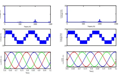
Also, to show that the UST and LST states do not introduce any significant harmonic distortion to the output
line-to-line voltage, the same dc-link voltage was used for the non-boost mode (i.e., 2E = 120 V, TULST/T = 0) and
the boost mode (2E = 120/1.53 V, TULST/T = 0.35) and their harmonic performances compared as shown in Fig.
11.
(a) Without shoot-through, THD = 37.77% (b) With shoot-through, THD = 37.26%
Fig.11. Comparison of non-shoot-through operation and ULST operation with the same dc-link voltage
0 5000 10000 15000
0 50 100 Frequency (Hz) L in e -t o -li n e v o lt a g e ( V ) -150 0 150 L in e -t o -li n e v o lt a g e ( V )
0.16 0.165 0.17 0.175 0.18 0.185 0.19 0.195 0.2
-1 0 1 Time (s) L in e c u r r e n t s ( A )
0 5000 10000 15000
0 50 100 Frequency (Hz) L in e -t o -li n e v o lt a g e ( V ) -150 0 150 L in e -t o -li n e v o lt a g e ( V )
[image:20.595.93.523.437.714.2]Lastly, the simulation results of the carrier-based PWM described in [36] using the same parameters as those
of the proposed SVM strategy are shown in Figs. 12 and 13 and the total harmonic distortion (THD) of the output
line-to-line voltage compared to that of the proposed SVM strategy in Table VI.
Fig.12. Simulation Results for Carrier based PWM (Top to Bottom): Spectrum of line voltage,
Line-to-line Voltage and Line Currents when M = 0.825 and TULST/T =0
Fig.13. Simulation Results for Carrier based PWM (Top to Bottom): Spectrum of line voltage,
Line-to-line Voltage and Line Currents when M = 0.825 and TULST/T =0.35
0 5000 10000 15000
0 50 100 150 Frequency (Hz) Li ne -to -li ne vo lta ge (V ) -200 0 200 Li ne -to -li ne vo lta ge (V )
0.02 0.03 0.04 0.05 0.06 0.07 0.08 0.09 0.1
-1.5 0 1.5 Time (s) Li ne cu rre nt s (A )
0 5000 10000 15000
0 50 100 150 Frequency (HZ) Li ne -to -li ne vo lta ge (V ) -200 0 200 Li ne -to -li ne vo lta ge (V )
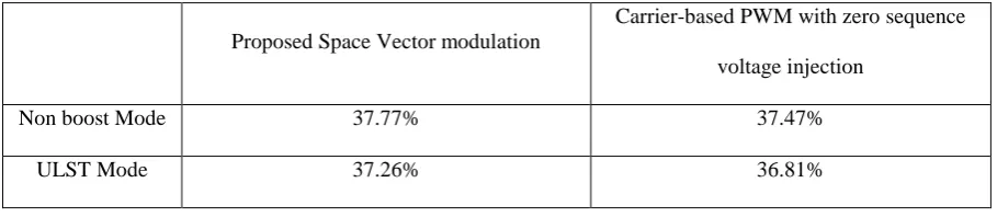
TABLE VI
COMPARISON OF THD OF PROPOSED SVM AND CARRIER-BASED PWM WITH ZERO SEQUENCE
VOLTAGE INJECTION
Proposed Space Vector modulation
Carrier-based PWM with zero sequence
voltage injection
Non boost Mode 37.77% 37.47%
ULST Mode 37.26% 36.81%
From Table VI, it can be concluded that the harmonic performance of the proposed SVM strategy is comparable
to the carrier-based PWM with zero sequence voltage injection strategy described in [36] and hence is a
competitive alternative for modulating the Z-source NPC inverter.
B. Experimental Verification
The simulation results presented in Section V-A have been validated experimentally. A balanced RL load
consisting of 57.6 Ω resistive bank and 35.5mH inductive bank was used. First, the modulation index, M and
shoot-through ratio, TULST/T were set to 0.9 and 0, respectively for the non-boost case. The waveforms from the
prototype are shown in Fig.14, from which is noted that the inverter dc-link voltage is not boosted but maintained
at 120 V by the dc source. The spectrum of the output line-to-line voltage shows a fundamental component of
peak value 101 V compared to the expected value of 108 V. The voltage across the Z-source capacitors (Vc1, Vc2
= Vc) is also maintained at 120 V. Good quality sinusoidal output currents were also obtained.
Next, with M maintained at 0.9 and TULST/T increased to 0.2 (B’ = 1.25), Fig.15 shows corresponding boosted
waveforms. Here, it is noted that the output line-to-line voltage has been boosted to about 145 V compared to an
expected value of 150 V. The spectrum of the output line-to-line voltage also gives a fundamental value of 123 V
compared to an expected value of (1.25*108 = 135 V). The line currents are also observed to have been boosted.
Also, the Z-source capacitor voltage was boosted to about 132 V compared to an expected value of 135 V. The
effective dc-link voltage seen by the NPC circuitry was also observed to have assumed two distinct voltage levels
attributed to the fact that the converter semiconductors and passive components were considered to be ideal in the
derivation of the previous equations.
Fig.14. Experimental waveforms of REC Z-source NPC inverter (Top to Bottom): Spectrum of Line-to-line
Voltage, Line-to-line voltage, Line Currents, Capacitor voltage and DC-link voltage when M = 0.9 and TULST/T
= 0
0 5000 10000 15000
0 50 100 150 Frequency (Hz) Li ne -t o-lin e vo lta ge ( V ) -150 0 150 Li ne -t o-lin e vo lta ge ( V ) -1.5 0 1.5 Li ne cu rr en ts ( A ) 0 75 150 C ap ac ito r vo lta ge ( V )
0.020 0.03 0.04 0.05 0.06 0.07 0.08 0.09 0.1
Fig.15. Experimental waveforms of REC Z-source NPC inverter (Top to Bottom): Spectrum of Line-to-line
Voltage, Line-to-line voltage, Line Currents, Capacitor voltage and DC-link voltage when M = 0.9 and TULST/T
= 0.2
V. CONCLUSION
In this paper, a modified space vector modulation for a REC Z-source NPC inverter is presented. Using
carefully inserted upper and lower shoot-through states to the traditional NPC inverter state sequence, the REC
Z-Source NPC inverter functions with the correct volt-second average and voltage boosting capability regardless
of the angular position of the reference vector. The insertion of the shoot-through states were such that the number
of device commutations were kept at a minimum of six per sampling period, similar to that needed by a traditional
NPC inverter. The presented concepts have been verified in simulations and validated experimentally using a
three-phase REC Z-source NPC inverter prototype.
REFERENCES
[1] S. Busquets-Monge, J. Rocabert, P. Rodriguez, S. Alepuz, and J. Bordonau, "Multilevel Diode-Clamped Converter for Photovoltaic Generators With Independent Voltage Control of Each Solar Array,"
Industrial Electronics, IEEE Transactions on, vol. 55, pp. 2713-2723, 2008.
[2] Z. Jing, H. Yunlong, H. Xiangning, T. Cheng, C. Jun, and Z. Rongxiang, "Multilevel Circuit Topologies Based on the Switched-Capacitor Converter and Diode-Clamped Converter," Power Electronics, IEEE
Transactions on, vol. 26, pp. 2127-2136, 2011.
0 5000 10000 15000
0 50 100 150 Frequency (Hz) Li ne -t o-lin e vo lta ge ( V ) -150 0 150 Li ne -t o-lin e vo lta ge ( V ) -1.5 0 1.5 Li ne cu rr en ts ( V ) 0 50 100 150 C ap ac ito r vo lta ge (V )
0.020 0.03 0.04 0.05 0.06 0.07 0.08 0.09 0.1
[3] H. Jwu-Sheng, C. Keng-Yuan, S. Te-Yang, and T. Chi-Him, "Analytical Solutions of Multilevel Space-Vector PWM for Multiphase Voltage Source Inverters," Power Electronics, IEEE Transactions on, vol. 26, pp. 1489-1502, 2011.
[4] Z. Zhengming, Z. Yulin, G. Hongwei, Y. Liqiang, and L. Ting, "Hybrid Selective Harmonic Elimination PWM for Common-Mode Voltage Reduction in Three-Level Neutral-Point-Clamped Inverters for Variable Speed Induction Drives," Power Electronics, IEEE Transactions on, vol. 27, pp. 1152-1158, 2012.
[5] S. Pengwei, L. Chuang, L. Jih-Sheng, and C. Chien-Liang, "Cascade Dual Buck Inverter With Phase-Shift Control," Power Electronics, IEEE Transactions on, vol. 27, pp. 2067-2077, 2012.
[6] J. Ebrahimi, E. Babaei, and G. B. Gharehpetian, "A New Topology of Cascaded Multilevel Converters With Reduced Number of Components for High-Voltage Applications," Power Electronics, IEEE
Transactions on, vol. 26, pp. 3109-3118, 2011.
[7] C. Govindaraju and K. Baskaran, "Efficient Sequential Switching Hybrid-Modulation Techniques for Cascaded Multilevel Inverters," Power Electronics, IEEE Transactions on, vol. 26, pp. 1639-1648, 2011. [8] S. Jie, S. Schroeder, R. Roesner, and S. El-Barbari, "A Comprehensive Study of Neutral-Point
Self-Balancing Effect in Neutral-Point-Clamped Three-Level Inverters," Power Electronics, IEEE
Transactions on, vol. 26, pp. 3084-3095, 2011.
[9] L. Jin, L. Jinjun, D. Boroyevich, P. Mattavelli, and X. Yaosuo, "Three-level Active Neutral-Point-Clamped Zero-Current-Transition Converter for Sustainable Energy Systems," Power Electronics, IEEE
Transactions on, vol. 26, pp. 3680-3693, 2011.
[10] X. Huafeng and X. Shaojun, "Transformerless Split-Inductor Neutral Point Clamped Three-Level PV Grid-Connected Inverter," Power Electronics, IEEE Transactions on, vol. 27, pp. 1799-1808, 2012. [11] J. Pou, J. Zaragoza, S. Ceballos, M. Saeedifard, and D. Boroyevich, "A Carrier-Based PWM Strategy
With Zero-Sequence Voltage Injection for a Three-Level Neutral-Point-Clamped Converter," Power
Electronics, IEEE Transactions on, vol. 27, pp. 642-651, 2012.
[12] S. S. Jayasinghe, D. D. Vilathgamuwa, and U. K. Madawala, "Diode-Clamped Three-Level Inverter-Based Battery/Supercapacitor Direct Integration Scheme for Renewable Energy Systems," Power
Electronics, IEEE Transactions on, vol. 26, pp. 3720-3729, 2011.
[13] T. A. Meynard and H. Foch, "Multi-level conversion: high voltage choppers and voltage-source inverters," in Power Electronics Specialists Conference, 1992. PESC '92 Record., 23rd Annual IEEE, 1992, pp. 397-403 vol.1.
[14] S. Thielemans, A. Ruderman, B. Reznikov, and J. Melkebeek, "Improved Natural Balancing With Modified Phase-Shifted PWM for Single-Leg Five-Level Flying-Capacitor Converters," Power
Electronics, IEEE Transactions on, vol. 27, pp. 1658-1667, 2012.
[15] B. P. McGrath and D. G. Holmes, "Enhanced Voltage Balancing of a Flying Capacitor Multilevel Converter Using Phase Disposition (PD) Modulation," Power Electronics, IEEE Transactions on, vol. 26, pp. 1933-1942, 2011.
[16] A. K. Gupta and A. M. Khambadkone, "A Simple Space Vector PWM Scheme to Operate a Three-Level NPC Inverter at High Modulation Index Including Overmodulation Region, With Neutral Point Balancing," Industry Applications, IEEE Transactions on, vol. 43, pp. 751-760, 2007.
[17] B. Abdul Rahiman, G. Narayanan, and V. T. Ranganathan, "Modified SVPWM Algorithm for Three Level VSI With Synchronized and Symmetrical Waveforms," Industrial Electronics, IEEE Transactions on, vol. 54, pp. 486-494, 2007.
[18] J. Pou, J. Zaragoza, P. Rodriguez, S. Ceballos, V. M. Sala, R. P. Burgos, and D. Boroyevich, "Fast-Processing Modulation Strategy for the Neutral-Point-Clamped Converter With Total Elimination of Low-Frequency Voltage Oscillations in the Neutral Point," Industrial Electronics, IEEE Transactions on, vol. 54, pp. 2288-2294, 2007.
[19] Y. Suh, J. K. Steinke, and P. K. Steimer, "Efficiency Comparison of Voltage-Source and Current-Source Drive Systems for Medium-Voltage Applications," Industrial Electronics, IEEE Transactions on, vol. 54, pp. 2521-2531, 2007.
[20] L. Xiao, Z. Wenping, L. Haijin, X. Ren, C. Min, S. Guoqiao, and X. Dehong, "Power Management Unit With Its Control for a Three-Phase Fuel Cell Power System Without Large Electrolytic Capacitors,"
Power Electronics, IEEE Transactions on, vol. 26, pp. 3766-3777, 2011.
[23] X. Li, W. Zhang, C. Du, X. Wu, and D. Xu, "Neutral point voltage control for three-level fuel cell power conversion system," in Power Electronics for Distributed Generation Systems (PEDG), 2010 2nd IEEE
International Symposium on, 2010, pp. 122-128.
[24] W. Rong-Jong, W. Wen-Hung, and L. Chung-You, "High-Performance Stand-Alone Photovoltaic Generation System," Industrial Electronics, IEEE Transactions on, vol. 55, pp. 240-250, 2008.
[25] F. Z. Peng, "Z-source inverter," Industry Applications, IEEE Transactions on, vol. 39, pp. 504-510, 2003. [26] S. M. Dehghan, M. Mohamadian, A. Yazdian, and F. Ashrafzadeh, "A Dual-Input Dual-Output Z-Source
Inverter," Power Electronics, IEEE Transactions on, vol. 25, pp. 360-368, 2010.
[27] P. C. Loh, F. Gao, T. Pee-Chin, and F. Blaabjerg, "Three-Level AC-DC-AC Z-Source Converter Using Reduced Passive Component Count," Power Electronics, IEEE Transactions on, vol. 24, pp. 1671-1681, 2009.
[28] P. Kiwoo, L. Kyo-Beum, and F. Blaabjerg, "Improving Output Performance of a Z-Source Sparse Matrix Converter Under Unbalanced Input-Voltage Conditions," Power Electronics, IEEE Transactions on, vol. 27, pp. 2043-2054, 2012.
[29] N. Minh-Khai, L. Young-Cheol, and K. Yong-Jae, "A Modified Single-Phase Quasi-Z-Source AC-AC Converter," Power Electronics, IEEE Transactions on, vol. 27, pp. 201-210, 2012.
[30] X. Liu, P. C. Loh, P. Wang, and X. Han, "Improved Modulation Schemes for Indirect Z-source Matrix Converter With Sinusoidal Input and Output Waveforms," Power Electronics, IEEE Transactions on,
vol. 27, pp. 4039-4050, 2012.
[31] B. Ge, Q. Lei, W. Qian, and F. Z. Peng, "A Family of Z-Source Matrix Converters," Industrial
Electronics, IEEE Transactions on, vol. 59, pp. 35-46, 2012.
[32] H. Cha, F. Z. Peng, and D. W. Yoo, "Distributed Impedance Network (Z-Network) DC-DC Converter,"
Power Electronics, IEEE Transactions on, vol. 25, pp. 2722-2733, 2010.
[33] S. J. Amodeo, H. G. Chiacchiarini, and A. R. Oliva, "High-Performance Control of a DC-DC Z-Source Converter Used for an Excitation Field Driver," Power Electronics, IEEE Transactions on, vol. 27, pp. 2947-2957, 2012.
[34] P. C. Loh, F. Gao, F. Blaabjerg, F. Shi Yun Charmaine, and S. Kong Ngai Jamies, "Pulsewidth-Modulated Z-Source Neutral-Point-Clamped Inverter," Industry Applications, IEEE Transactions on,
vol. 43, pp. 1295-1308, 2007.
[35] P. C. Loh, L. Sok Wei, F. Gao, and F. Blaabjerg, "Three-Level Z-Source Inverters Using a Single LC
Impedance Network," Power Electronics, IEEE Transactions on, vol. 22, pp. 706-711, 2007.
[36] P. C. Loh, F. Gao, F. Blaabjerg, and L. Sok Wei, "Operational Analysis and Modulation Control of Three-Level Z-Source Inverters With Enhanced Output Waveform Quality," Power Electronics, IEEE
Transactions on, vol. 24, pp. 1767-1775, 2009.
[37] S. M. Dehghan, E. Seifi, M. Mohamadian, and R. Gharehkhani, "Grid connected DG systems based on Z-source NPC inverters," in Power Electronics, Drive Systems and Technologies Conference (PEDSTC),
2011 2nd, 2011, pp. 104-110.
[38] F. Xupeng, C. Maoyong, and C. Zhiqiao, "Z-source AC-DC-AC converter for mining applications," in
Electrical Machines and Systems (ICEMS), 2010 International Conference on, 2010, pp. 44-47.
[39] J. T. Boys and P. G. Handley, "Harmonic analysis of space vector modulated PWM waveforms," Electric
Power Applications, IEE Proceedings B, vol. 137, pp. 197-204, 1990.
[40] D. G. Holmes, "The general relationship between regular-sampled pulse-width-modulation and space vector modulation for hard switched converters," in Industry Applications Society Annual Meeting,
1992., Conference Record of the 1992 IEEE, 1992, pp. 1002-1009 vol.1.
[41] H. W. van der Broeck, H. C. Skudelny, and G. V. Stanke, "Analysis and realization of a pulsewidth modulator based on voltage space vectors," Industry Applications, IEEE Transactions on, vol. 24, pp. 142-150, 1988.
[42] F. Z. Peng, "Z-source inverter," in Industry Applications Conference, 2002. 37th IAS Annual Meeting.
Conference Record of the, 2002, pp. 775-781 vol.2.
[43] P. C. Loh, D. M. Vilathgamuwa, C. J. Gajanayake, L. T. Wong, and C. P. Ang, "Z-Source Current-Type Inverters: Digital Modulation and Logic Implementation," Power Electronics, IEEE Transactions on,
vol. 22, pp. 169-177, 2007.
[44] P. C. Loh, F. Gao, and F. Blaabjerg, "Embedded EZ-Source Inverters," Industry Applications, IEEE
Transactions on, vol. 46, pp. 256-267, 2010.
[45] F. Gao, P. C. Loh, F. Blaabjerg, R. Teodorescu, and D. M. Vilathgamuwa, "Five-level Z-source diode-clamped inverter," Power Electronics, IET, vol. 3, pp. 500-510, 2010.
[46] B. P. McGrath, D. G. Holmes, and T. A. Lipo, "Optimised space vector switching sequences for multilevel inverters," in Applied Power Electronics Conference and Exposition, 2001. APEC 2001.