EVALUATION OF THE STRESS PATTERNS ON THE BONE AROUND
AND ANGULATED ABUTMENTS: A FINITE
*Dr. Ramya Kumari, S., Dr. Krishna
Sibar Institute
ARTICLE INFO ABSTRACT
Background
abutments or a combination of angulated and straight abutments were used to support prostheses. Implant placement re
abutments to fulfill esthetic and functional objectives in selected cases.
Aim and Objective
implant of vertical and angulated abutments using finite element analysis. The objective was to evaluate and compare the Von misesstress (overall stress) di
(100,20
Materials and Method
generated to simulate the D tomography scans.
ANSYS software. Axial loads of 178N was applied on the cingulum area of all the models.
Results
observed at overall bone implant interface as angulations of abutments increased from 0 axial loading in D2 and D3 density types of bone.
Conclusion
increases from 0
differences was observed in magnitude of stresses in both D2 and D3 types of bone.
Copyright©2017, Dr. Ramya Kumari et al. This is an open use, distribution, and reproduction in any medium, provided
INTRODUCTION
The goal of modern dentistry is to return patients to oral health in a predictable fashion. The partial and completely edentulous patients may unable to recover normal function, esthetics, comfort or speech with traditional removable prosthesis. Compared with traditional methods of tooth replacement, the implant prosthesis offers increased longevity, improved function, bone preservation and better psycholo
(Carl.E.Misch,1999). A critical determinant for placement of an implant is the height and width of bone available in an edentulous sites. The clinician also needs to evaluate the angulation of the ridge, bony undercuts, shape of the arch, maxillomandibular relationships, position of mandibular canal and proximity of paranasal sinuses are considered before placing the implants. Ideally, implants should be placed parallel to each other and to adjacent teeth and be aligned vertically with axial forces. However, achieving this may not be possible owing to deficiencies in the ridge’s anatomy.
*Corresponding author: Ramya Kumari,
Sibar Institute of Dental Sciences, Takkellapadu, Guntur
ISSN: 0975-833X
Article History:
Received 18th June, 2017
Received in revised form 10th July, 2017
Accepted 05th August, 2017
Published online 30th September, 2017
Citation: Dr. Ramya Kumari, S., Dr. Krishna Kishore, K., Dr. Gopinadh, A. and Dr. Sandeep, Ch.
around an implant using vertical and angulated abutments: A finite element analysis study
Key words:
FEA (Finite Element Analysis), D2 density bone,
D3 density bone,
Computed Tomography (CT).
RESEARCH ARTICLE
EVALUATION OF THE STRESS PATTERNS ON THE BONE AROUND AN IMPLANT USING VERTICAL
AND ANGULATED ABUTMENTS: A FINITE ELEMENT ANALYSIS STUDY
Krishna Kishore, K., Dr. Gopinadh, A. and
Institute of Dental Sciences, Takkellapadu, Guntur
ABSTRACT
Background: Dental implants offer several benefits over conventional tooth replacements.
abutments or a combination of angulated and straight abutments were used to support prostheses. Implant placement relates to emergence profile of the implant prosthesis and use of preangulated abutments to fulfill esthetic and functional objectives in selected cases.
Aim and Objective: The aim of the study was to evaluate stress patterns on the bone around an implant of vertical and angulated abutments using finite element analysis. The objective was to evaluate and compare the Von misesstress (overall stress) distribution of vertical (0
,200& 300) abutments in D2 and D3 types of density of bone.
Materials and Method: This study was conducted using finite element method. Two models were generated to simulate the D2 and D3 density bone using the digitized data computed from the computer
tomography scans. Four groups of models with 00,100,200 and 30
ANSYS software. Axial loads of 178N was applied on the cingulum area of all the models.
Results: The results showed an increased magnitude of stresses of approximately 4.4 folds was observed at overall bone implant interface as angulations of abutments increased from 0
axial loading in D2 and D3 density types of bone.
Conclusion: This concludes that Von Mises stresses were higher in 30
increases from 00, 100, 200 & 300 on axial loading of 178N. However there was no significant
differences was observed in magnitude of stresses in both D2 and D3 types of bone.
open access article distributed under the Creative Commons Attribution provided the original work is properly cited.
The goal of modern dentistry is to return patients to oral health The partial and completely edentulous recover normal function, esthetics, comfort or speech with traditional removable prosthesis. Compared with traditional methods of tooth replacement, the implant prosthesis offers increased longevity, improved function, bone preservation and better psychological results ,1999). A critical determinant for placement of an implant is the height and width of bone available in an edentulous sites. The clinician also needs to evaluate the angulation of the ridge, bony undercuts, shape of the arch, illomandibular relationships, position of mandibular canal and proximity of paranasal sinuses are considered before Ideally, implants should be placed parallel to each other and to adjacent teeth and be aligned orces. However, achieving this may not be possible owing to deficiencies in the ridge’s anatomy.
Sciences, Takkellapadu, Guntur
To compensate for ridge topography that is less than ideal, clinician can follow one of several scenarios to enhance placement of implants: augment the ridge, change the intended location of an implant by sinus elevation and nerve repositioning or insert an implant with an angled trajectory (John Cavallaro, 2011). The use of angulated abutments may provide a variety of advantages: facilitating placement of an implant with greater dimensions in width and height, avoiding guided bone regeneration (GBR) procedures, reduced treatment time, fees and aid the clinicia
to anatomical structures when placing the implants.
angled abutments facilitates paralleling the nonaligned implants, thereby making prosthesis fabrication easier. angulation of these abutments varies from 15
Prasad, 2013). Clinical comparative studies of implant with straight abutments and angulated abutments showed that the bone loss or survival of angled abutment was not significantly different from straight abutment,
measurements and photo elastic models of Brosh finite element analysis of Canay
abutment were subjected to higher stress values around the cervical region than those observed for straight abutment
International Journal of Current Research
Vol. 9, Issue, 09, pp.58206-58212, September, 2017
Kumari, S., Dr. Krishna Kishore, K., Dr. Gopinadh, A. and Dr. Sandeep, Ch. 2017. “Evaluation of the stress patterns on the bone
around an implant using vertical and angulated abutments: A finite element analysis study”, International Journal of Current Res
IMPLANT USING VERTICAL
ELEMENT ANALYSIS STUDY
Gopinadh, A. and Dr. Sandeep, Ch.
implants offer several benefits over conventional tooth replacements. Angulated abutments or a combination of angulated and straight abutments were used to support prostheses. lates to emergence profile of the implant prosthesis and use of preangulated abutments to fulfill esthetic and functional objectives in selected cases.
: The aim of the study was to evaluate stress patterns on the bone around an implant of vertical and angulated abutments using finite element analysis. The objective was to stribution of vertical (00) and angulated
: This study was conducted using finite element method. Two models were e digitized data computed from the computer and 300 abutments were analysed in ANSYS software. Axial loads of 178N was applied on the cingulum area of all the models.
ncreased magnitude of stresses of approximately 4.4 folds was observed at overall bone implant interface as angulations of abutments increased from 00 to 300 under
were higher in 300 angulated abutment and on axial loading of 178N. However there was no significant differences was observed in magnitude of stresses in both D2 and D3 types of bone.
ribution License, which permits unrestricted
To compensate for ridge topography that is less than ideal, the clinician can follow one of several scenarios to enhance placement of implants: augment the ridge, change the intended location of an implant by sinus elevation and nerve repositioning or insert an implant with an angled trajectory The use of angulated abutments may provide a variety of advantages: facilitating placement of an implant with greater dimensions in width and height, avoiding guided bone regeneration (GBR) procedures, reduced treatment time, fees and aid the clinician in avoiding damage to anatomical structures when placing the implants. The use of angled abutments facilitates paralleling the nonaligned implants, thereby making prosthesis fabrication easier. The
angulation of these abutments varies from 150to 350 (Krishna
Clinical comparative studies of implant with straight abutments and angulated abutments showed that the bone loss or survival of angled abutment was not significantly t abutment, however the strain gauge
ts and photo elastic models of Brosh et al and
finite element analysis of Canay et al. revealed that angled
abutment were subjected to higher stress values around the cervical region than those observed for straight abutment
INTERNATIONAL JOURNAL OF CURRENT RESEARCH
Evaluation of the stress patterns on the bone
(Arun Kumar et al., 2013). Angled abutments decrease the stress and promote better stress distribution on bone
surrounding the single-unit dental implants. (Tian et al., 2012)
However, increased stresses on implants and bone have been associated with use of angled abutments. A finite element analysis was chosen for this study as it is useful tool in estimating stress distribution in the contact area of the implant with the bone.
MATERIAL AND METHODS
As the finite element method requires a huge amount of computation, its application should be supported by advanced computer technology. The Von mises stresses on axial loading of implants along with straight and angulated abutments were calculated using three dimensional finite element models
created on a workstation computer with following
configurations
Hardware
Intel(R) Core(TM) i3-3120M CPU Processor with a speed of 2.50 GHz 4 GB Ram.
Software
ANSYS (R 14.5 Version), ANSYS corporation US.
Application of finite element analysis
Maxillary bone
A three dimensional finite element solid model of the premaxilla was constructed based on CT data. It has been observed in numerous investigations that to assess stress distribution around dental implants, it is not necessary to build a finite element model of the entire maxillary arch, because of its complicated and individually different geometry. In this study the maxillary bone was not completely modeled, a part of the section of the maxilla in anterior esthetic zone involving D2 and D3 density was generated.
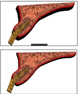
Finite element models
Two mathematical models were developed to simulate the D2
and D3 density bone using the digitized data computed from
the computer tomography scans. The isotropic cortical bone
thickness was 1.0 mm for D2 and 0.5 mm for D3 on the facial,
lingual and occlusal aspects of the bone. The cancellous bone had a density approximately 17% that of cortical bone around an implant in both the models of model-1 and model-2 of maxillary bone of D2 type and maxillary bone of D3 type as shown in Figures 1a and 1b.
Implant model construction
The implant fixture model generated for the study was 4.2 × 13 mm. The simulated implant was a self-threaded, single piece, cylindrical fixture, with commerciallypure titaniumproperties.
Cement able abutments of angulations (00,100,20° and 30°)
were used and analysedusing Finite Element Analysis ANSYS software. Models were meshed with a four node tetrahedron elementsas shown in Figures 2a,2b,2c and 2d.Depending on the implant size the number of elements and nodes in each group of model was shown in Table-1.
Table 1. No. of elements and nodes
Number of elements Number of Nodes
Straight 100442 21191
10deg 100565 21201
20deg 100669 21248
30dege 100594 21216
Prosthesis model construction
Prosthesis superstructure of angulated abutments were modeled based on the original patient’s clinical crown design from the CT dataset. Four different abutment angulations
respectively 00,100,200,300 were used. The design and
geometry of the model were assumed to be symmetric at 1.5 to 3.4 mm in thickness, 12.0 to 14.1 mm in width, and 15.0 to 17.3 mm in height. The prosthesis and its framework were modeled as one piece and assumed to be made with similar properties of titanium alloy for the analysis. After modeling the components were meshed using the software. All materials used in the models were considered to be isotropic, homogenous, static and linearly elastic. Axial loads of 178Nwill be applied on the cingulum area of all the models as shown in Figure 3.The loading was based on the average axial loading observed in the natural dentition (Hellsing, 1980)
Interface conditions
To simulate ideal osseointegration the implants along their entire interface, were rigidly anchored in the bone model. The same type of contact was provided at all material interfaces as shown in Table-2 and Table-3. The friction coefficient, μ, for all contacting surfaces was set at 0.3, to simulate an immediate
loading condition (Jian-Ping Geng et al., 2001)
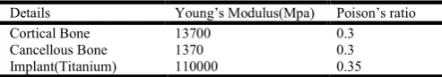
[image:2.595.314.549.75.128.2]Properties of the members
Table 2. D2 Bone Properties
Details Young’s Modulus(Mpa) Poison’s ratio
Cortical Bone 13700 0.3
Cancellous Bone 1370 0.3
Implant(Titanium) 110000 0.35
Table 3. D3 Bone Properties
Details Young’s Modulus(Mpa) Poison’s ratio
Bone(Cortical & Cancellous) 10600 0.3
Implant(Titanium) 110000 0.35
Methodology
A series of CT image datasets of premaxilla model,
implant models and prosthesis models were taken and meshed for the analysis.
The conventional implant was virtually placed in the anterior region of the maxilla adjacent to the lateral incisor. All models were converted into four nodes of the tetrahedral element type in finite element analysis
ANSYS software. The total number of elements for the
D2 model was 3,02,380 tetrahedral elements while the D3model had a total of 3,83,482 tetrahedral elements.
[image:2.595.309.556.495.538.2]stresses occurring for angulated abutments (0°, 10°, 20°, 30°) was interpreted and to compare the stress distribution on the bone around an implant in D2 and D3 types of density of bone.
Fig. 1a&1b. Maxillary bone of D2 density and D3 density
Fig. 2a&2b. Straight and 100 abutment model with elements,
nodes
[image:3.595.307.560.51.356.2]Fig. 2c&2d. 200 and 300 abutment model with elements, nodes
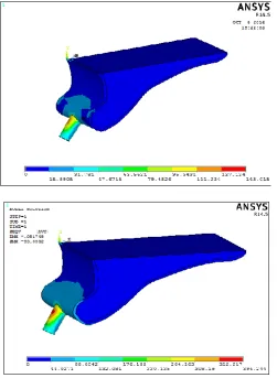
[image:3.595.40.287.110.442.2] [image:3.595.42.556.421.771.2] [image:3.595.38.289.474.773.2]Fig. 4a&4b. Overall stress of 00 and 100 abutment in D2 bone
Fig. 4c&4d. Overall stress of 200 and 300 abutment in D2 bone
Fig. 5a&5b. Overall stress of 00 and 100 abutment in D3 bone
Fig. 5c&5d. Overall stress of 200 and 300 abutment in D3 bone
Table 1. Comparison of Magnitude of stresses (Mpa) recorded at different angulations of angulated abutments under axial loading
of 178N in D2 density bone
Zero 10deg 20deg 30deg
Overall stress(Mpa) 93.05 118.512 143.015 396.244
D2 Bone
Table 2. Comparision of Magnitude of stresses (Mpa) recorded at different angulations of angulated abutments under axial loading
of 178N in D3 density bone
Zero 10deg 20deg 30deg
Overall stress(Mpa) 94.4093 122.477 148.723 395.997
[image:4.595.35.560.37.625.2] [image:4.595.40.292.244.588.2] [image:4.595.301.558.257.613.2] [image:4.595.41.290.620.793.2]RESULTS
1)Magnitude of stresses in d2 density bone
A)Order of the magnitude of OVERALL STRESS in axial loading:
300 Abutment ˃ 200 Abutment˃ 100 Abutment˃ 00 Abutment
On Axial Loading (178 N) as shown in Fig. 4a,4b,4c and 4d.
Graph 1. Overall stress of 00, 100, 200 and 300 abutment models in D2 density bone
II) Magnitude of stresses in d3 density bone
A)Order of the magnitude of OVERALL STRESS in axial loading:
300 Abutment ˃ 200 Abutment˃ 100 Abutment˃ 00 Abutment
On Axial Loading (178 N) as shown in Fig 5a,5b,5c and 5d.
Graph 2. Overall stress of 00, 100, 200 and 300 abutment models in D2 density bone
The results showed an increased magnitude of stresses approximately 4.4 folds was observed at overall bone implant
interface as the angulations of abutments increased from 00 to
300 under axial loading in D2 and D3 types of density of bone as shown in Table-1 and Table-2. However no significant differences was observed in magnitude of stresses in both D2 and D3 types of bone.
DISCUSSION
Stress and strain have been shown to be important parameters for crestal bone maintenance and implant survival. The higher the crestal stress, the higher the risk of crestal bone loss. The
higher the stress factors throughout the implant the greater the
risk factor for implant failure (Meijer et al., 1992). Following
tooth extraction in the anterior part of maxilla the horizontal bone resorption is almost twice as pronounced as vertical resorption. Lack of bone volume always result in exposure of implant surface, decreased bone-implant interface and finally implant failure. This can be managed either by surgical correction or by positioning the implant in the area with greatest available bone. This is made possible by carefully planned the cases, with use of angled implant abutments. Eger
et al and Sethi et al concluded that angled abutments may
considered a suitable restorative option when implants are not
placed in ideal axial positions (Arun Kumar et al., 2013).
Especially in the maxilla in an esthetic zone an angled abutment allows the placement of implants in the most favorable quantity and quality of available bone in patients with compromised osseous anatomy. In a study, survivability of implants used with angulated abutments ranging from 0-45 degrees, it was observed that the survival function rates of implants with angulated and straight abutments was the same
(Sethi et al., 2000). This study was conducted to gain more
insight into the influence of different angulated implant abutments on the stress distribution in the alveolar bone surrounding the implant under axial loading.
Xavier et al. in his study, he concluded that the model with the
straight abutment had slightly higher values of microstrain than
the model with the angled abutment (Xavier et al., 2007).
Cardelli et al. in his study, he reported that bone resorption
was recorded at the level of implant neck in close contact with cortical bone. As far as the use of angulated abutment is concerned they concluded that it is necessary to use them and
suggested to not exceed the limit of 250 (Cardelli et al., 2009).
Cavallaro et al. and RohitBahuguna et al. they both evaluated
five abutment divergences (00,150,250,300and350). On the basis
of available data in the literature, they concluded that though the compressive and tensile stresses generated through axial and oblique loading increase as the abutment angulation increases yet they are within the tolerance limits of the bone
(Cavallaro et al., 2011; Rohit Bahuguna et al., 2013). Arun K
et al. conducted a study to compare the stress distribution
around implant in different bone qualities of D1,D2,D3 and D4 with straight and angled abutments using three dimensional finite element analysis. They concluded that Von mises stress values were increased as the bone quality changes from D1 to
D4 (Arun Kumar et al., 2013). In this study the stress
distribution around implant in different bone qualities of D2 and D3 with straight and angled abutments was studied using finite element analysis. The anterior teeth were subjected to maximum compressive stress during incising and the force was directed along the long axis of the tooth. In implant with straight abutment the force was directed along the long axis of abutment and implant which results in even distribution of stresses on the buccal and lingual side in D2 and D3 bone qualities. In angled abutments the force would be directed to the area of bone opposite to that of abutment inclination. As the density of the bone increased, the stresses were concentrated on the facial aspect for all the abutments These values are in accordance with the study done by Clelland and
Martin D Grass et al. (Clelland et al., 1995). Lin et al.
conducted an analysis of stress on single implants and reported that the cortical bone strain was higher for an angled abutment of 20 degrees than that for straight abutments and bone strain
increased as the bone density decreased (Lin et al., 2008).
implant with a 00,150 and 250 angulated abutment in D1 and D4 density bones using three dimensional FEA and reported
that maximum bone stress was obtained with 150 angulated
abutment (Danza et al., 2009). When the stress in the thin
(0.5mm) and the thick (1.0 mm) cortical bone due to four different angulated abutments subject to axial loading (178N) were evaluated, it was observed that the overall stress in both
the D2 and D3 models with 00,100,200 and 300 abutments, the
ΣEmax stress values were 93.05 to 396.24Mpa. However studies
state that within a load of 178 N, angulated abutments up to
200 can be placed in the anterior maxilla zone but further
clinical scientific evaluation needs to be done. The above reported results of this analysis correlate with findings of other studies that used different investigation methods. Certain limitations of finite element study should be taken into consideration that is geometry of the model was simplified, with a rectangular section. The resultant stress values obtained may not be accurate quantitatively but are generally accepted qualitatively. Chewing forces are dynamic in nature, whereas the study was conducted with static loads. Due to the limitations pertaining to the study, further research regarding three-dimensional finite element analysis combined with long term clinical evaluation has been suggested.
Conclusion
The following conclusions were drawn from the study
On axial loading of 178 N
The magnitude of overall stresses were maximum in the 300
abutment compared to those of 00, 100, 200 angulated
abutments. There was an increased magnitude of stresses of
approximately 4.44 folds higher respectively. But, no significant difference in magnitude of stresses was observed in both D2 and D3 density bones.
Conflicts of Interest: None
REFERENCES
Arun Kumar, G., Mahesh, B., George, D. 2013. Three dimensional finite element analysis of stress distribution around implant with straight and angled abutments in
different bone qualities. J Indian Prosthodont Soc., 13(4):
466-472.
Ashok Sethi, Thomas Kaus, Peter Sochor.2000. The use of angulated abutments in implant dentistry: Five-Year
clinical results of an ongoing prospective study. Int J Oral
Maxillofac Implants., 15:801-810.
Brosh, T., Raphael, P., Sudai, D. 1998. The influence of abutment angulation on strain and stresses along the implant bone interface: Comparison between two
experimental techniques. JProsthet Dent., 79:328-334.
Bruggenkate, CM., Sutter, F., Oosterbeek, HS., Schroeder,
A.1992. Indications for Angled Abutments. J Prosthet
Dent., 67:85-93.
Canay, S., Hersek, N., Akpinar, I., Asik, Z. 1996. Comparison of stress distribution around vertical and angled implants
with finite element analysis. Quintessence Int., 27:591-598.
Cardelli, P., Montani, M., Gallio, M., Biancolini, M., Brutti, C., Barlattani, A. 2009. Angulated abutments and
perimplantsstress: F.E.M Analysis. Oral and
Implantology., 1:3-10.
Clelland, NL., Lee, JK., Bimbenet, OC., Branthy, WA. 1995. A three dimensional finite element analysis of angled abutments for an implant placed in the anterior maxilla.
JProsthodont., 4(2):95-100.
Clelland, NL., Gilat, A., Glumphy, EA. 1993. A photoelastic and stain gauge analysis of angled abutments for an
implants system. IntJ Oral Maxillofac Implants.,
8:541-548.
Craig RG. 1993. Restorative dental materials, 9th ed. Mosby, pp. 54-55.
Danza, M., Palmieri, A., Farinella, F. 2009. Three dimensional finite element analysis to detect stress distribution in spiral
implants and surrounding bone. DentResJ., 6:59-64.
Dorothy E. Eger, John C. Gunsolley, Sylvan Feldman, 2000. Comparison of angled and straight abutments and their
effect on clinical outcomes: A preliminary report. Int J
Oral Maxillofac Implants., 15:819-823.
Eger, DE., Gunsolley, JC., Feldman, S.2000. Comparison of Angled and Standard Abutments and Their Effect on
Clinical Outcomes: A Preliminary Report. Int J of Oral and
Maxillofac Implants., 15:819-823.
Gelb, DA., Lazzara, RJ. 1993. Hierarchy of objectives in implant placement to maximize ethetics: Use of
pre-angulated abutments. Int J Periodont Rest Dent.,
13:277-289.
Geng, JP., Tan, KBC., Liu, GR. 2001. Application of finite element analysis in implant dentistry: A review of the
literature. J Prosthet Dent., 85:585-598.
Hellsing G.1980.On the regulation of interincisor bite force in
man. J Oral Rehabil., 7:403-411.
John Cavallaro, Gary Greenstein. 2011. Angled implant
abutments:Apractical application of available knowledge. J
American Dent Association., 142(2) : 150-158.
Krishna Prasad, DivyaMehra, Anupama Prasad. 2013. Angulated Abutments-A curve that sets everything straight.
Guident., 2(1) :16-21.
Michael Pampel, Ralf Wolf, Stefan Dietrich.2006.A
prosthodontic technique to improve the simplicity and the efficacy of angled abutments for divergent implant
situations:A technical note. Int J Oral MaxillofacImplants.,
21:320-324.
Ming LU, Tai F Chung, Hung Chan Kao. 2005. Clinical
application of angled abutments: A literature review. Chin
Dent J., 24:15-20.
Misch CE. 1999. Rational for dental implants. Contemporary Implant Dentistry. 2nd ed, St. Louis, pp. 45-49.
Pampel, M., Dent, M., Wolf, R., Dielrich, S. 2006. A
prosthodontics technique to improve the simplicity and the efficacy of angled abutments for divergent implant
situations: A technical note. Int J Oral Maxillofac
Implants., 21:320-324.
Papavasiliou, G., Kamposiora, P., Stephen, C., Felton, DA. 1996. Three-dimensional finite element analysis of stress distribution around single tooth implants as a function of bony support, prosthesis type and loading during function.
J Prosthet Dent., 76:633-640.
Pradeep, B., Liju, J., Vamsi, K., Padma, A. 2014. Influence of occlusal loading on stress patterns at the bone-implant interface by angulated abutments in the anterior maxilla:
A 3D FEA Study. Journal of Dental Implants, 4(1):3-10.
Rohit Bahuguna, Bhargavi Anand, Dheeraj Kumar, Himanshu
Aeran, Vishal Anand, Minkle Gulati. 2013. National
Jounal of Maxillofacial Surgery, 4(1):46-51.
an ongoing prospective study. Int J Oral Maxillofac
Implants., 15:801-810.
Thomas J.Balshi, Anders Ekfeldt, Torsten Stenberg, Luc Vrielinck.1997. Three-Year evaluation of Branemark
implants connected to angulated abutments. Int J Oral
Maxillofac Implants., 12:52-58.
Xavier, E.Saab, Jason, A.G, John M.P. 2007. Effect of abutment angulation on the strain on the bone around an
implant in the anterior maxilla: A FEA Study. J Prosthet
Dent., 97:85-92.