A PRACTICAL METHOD FOR RANGE MIGRATION COMPENSATION IN CHIRP RADAR
J. Li, H. Liu, and Z. He
Department of Electronic Engineering
University of Electronic Science and Technology of China Jianshe North Road, Chengdu 610054, China
Abstract—The echo signal characteristic of a chirp pulse train from a moving target is analyzed. It is pointed out that the range migration is caused by the migration exponential item (MEI) and can be compensated by removing the MEI. On this basis, we proposed a new practical compensation method with very low computation burden through shifting control on the matching weight coefficients. The parasitical sidelobes due to the quantization effect can be restrained effectively by storing multi-groups of weight. Simulation results proved the availability of the method.
1. INTRODUCTION
Range migration is an unavoidable problem in the imaging of moving targets or long time coherent integration. Target motion will influence the target detection in surveillance radar or the focus of imaging in SAR or ISAR [1–3]. Many researches on motion compensation containing range migration compensation have been done [3–9]. Typical migration compensation methods include range-bin realignment [4], envelope interpolation algorithm [9], Keystone transform [6, 7], time-frequency analysis [8], etc. The computation burden and the processing complexity are the problems facing these methods when used in practice. This paper aims at only range migration problem and investigats a practical compensation method with low additional computation burden.
The echo signal characteristic of a chirp pulse train from a moving target is analyzed at first. It is point out that the range migration is caused by the migration exponential item (MEI) of the
echo signal and can be compensated by removing the MEI before the processing of match filtering and coherent integration. On this basis, an implementary method by shifting control on the frequency domain weight coefficients of the digital match filter is put forward. This method combines the compensation processing with the match filtering, so it greatly reduces the additional computation burden. Due to the quantification effect of digital processing, this method will produce parasitic sidelobes in the output, as the processing results of range-bin realignment and envelope interpolation algorithms. By storing multi-groups of weight coefficients, the parasitic sidelobes can be depressed effectively.
Our discussion is based on the hypotheses: (1) The velocity of the target is constant during the coherent processing interval (CPI); (2) The range migration in a CPI is larger than the width of the pulse compression output, but far smaller than the width of the transmitted chirp pulse.
2. SIGNAL MODEL AND CHARACTERISTIC ANALYSIS
The effect on the radar electromagnetic wave due to the motion of a target presents the echo signal time scale change (time stretching or shrinking). Assume that the transmitted signal is s(t), then the echo from a moving target with velocity radial velocity v can be expressed as [10]:
sr(t) =ηs κ(t−t0) (1)
whereη is the amplitude of the echo signal (hereinafter assumeη= 1);
t0= 2R0/(c+v) is the delay of the wavefront; cis the velocity of light;
and R0 is the original distance of the target.
κ= (c+v)/(c−v) (2)
is the compressing coefficient.
When transmitting a chirp pulse train, s(t) can be expressed by
s(t) =
M−1
X
m=0
u(t−mT)ej2πfct
(3)
here,M is the amount of pulse burst;T denotes the PRI;fc represents
the carrier frequency; and
u(t) =rect
t TP
ej12µt 2
is the chirp signal; µis modulation rate; and Tp denotes the width of
the pulse. And
rect t Tp =
(1 0≤t≤T
p
0 else
(5)
According to (1) and (3), the received signal can be expressed as:
sr(t) = M−1
X
m=0
u(κ(t−t0)−mT)ej2πfc(κ(t−t0)) (6)
After mixing with the local oscillator signal, the output base band signal is:
srI(t) = M−1
X
m=0
u(κ(t−t0)−mT)ej2πfdte−jφ (7)
where fd= 2vfc/(c−v) is the Doppler frequency, andφ= 2πfcκt0 is
the initial phase of the echo signal. Denote tas:
t= ˆt+mT (8)
where ˆtis the “fast time” in a PRI, and m represents the “slow time” for different period. For simplification, we supposed that t0 ∈ [0, T].
Then the base band signal srI(t) can be expressed as a bidimensional
form:
srI(ˆt, m) =uκ(ˆt−t0) + (κ−1)mTej2πfd(ˆt+mT)e−jφ (9)
Define migration factor κv:
κv =κ−1 = 2v
c−v (10)
κv represents the relative amount of migration between adjacent PRIs.
According to (4) and (10), (9) can be expanded as:
srI(ˆt, m) =rect
κ(ˆt−t0) +κvmT TP
·ej12µ(κ(ˆt−t0)+κvmT) 2
·ej2πfd(ˆt+mT)
e−jφ
=rect
κ(ˆt−t0) +κvmT TP
·ej12µ(κ(ˆt−t0)) 2
ej2πfdˆt
·ej12µ[(κvmT) 2
−2κt0κvmT]
ej2πfdmTejµκˆtκvmT
Define:
U1 = ej 1
2µ(κ(ˆt−t0)) 2
ej2πfdˆt (12)
U2 = ej 1
2µ(κvmT) 2
e−jµt0κκvmT
ej2πfdmT (13)
U3 = ejµκˆtκvmT (14)
The total migration in a CPI is κvM T = 2vM T /(c−v), which
is far smaller than the width Tp of the chirp pulse before compressed,
and so
rect
κ(ˆt−t0) +κvmT Tp
≈rect
ˆ
t−t0 Tp
(15)
Then the base band signal can be expressed as:
srI(ˆt, m) =rect
ˆ
t−t0 TP
U1U2U3e−jφ (16)
3. CHARACTERISTIC ANALYSIS OF THE BASEBAND SIGNAL AND THE MEI
Obviously,U1(ˆt) is the common item of single chirp pulse echo from a
moving target, which can be processed by ordinary match filtering.
U2(m) is a function of slow timem. It can be written as
U2(m) =U21(m)U22(m)U23(m) (17)
where, U23(m) = ej2πfdmT is the normal element caused by Doppler
frequency, and U21(m) = ej 1
2µ(κvmT) 2
is an extra chirp component in the slow time, which will widen the Doppler bandwidth slightly.
U22(m) = e−jµt0κκvmT is a sine wave, whose frequency is determined
by t0, and U22 may change the Doppler frequency of the target, but it
does not influence the coherent integration.
Notice that U1 and U2 have nothing to do with the range
migration, and U3 = ejµκˆtκvmT is related not only to the fast time
ˆ
t, but also to the slow time m. Thereby, U3 is the determinant of
range migration and coherent integration loss. So we callU3migration
exponential item (MEI).
When tracking slow targets with narrowband signal, we have
κv ≈0, soU3 ≈1,U21≈1,U22≈1, and
srI(ˆt, m)≈rect
ˆ
t−t0 TP
ej12µ(κ(ˆt−t0)) 2
ej2πfdˆt
ej2πfdmT
The processing in the fast and slow times are mutually independent. The ordinary method is match filtering in the fast time and coherent integration using FFT algorithm in the slow time.
As the signal bandwidth is much wider and the target velocity is much higher, the migration factor κv becomes greater, and the range
migration across pulse repetition period can not be ignored. The loss of gain in coherent integration arising from MEI must be taken into account.
Since U3 is the determinant of range migration, we can eliminate
range migration by remove the MEI. And this can be achieved by multiplyingsrI(ˆt, m) withe−jµκˆtκvmT.
srIout(ˆt, m) =srI(ˆt, m)e−jµκˆtκvmT (19)
The above operation results in the change of Doppler frequency shift in each PRI, which then leads to the complementary migration of the signal envelope. The new signal matrixsrIout(ˆt, m) then can be
processed with the ordinary method.
4. RANGE MIGRATION COMPENSATION BASED ON SHIFTING THE MATCHING WEIGHT COEFFICIENTS As shown above, the range migration can be compensated by removing the MEI. This method is essentially based on the Doppler-range relationship of chirp signal, and it does not produce any parasitic sidelobes in the output as long as the compensation is accurate.
In this section, we will introduce a new practical method with low additional computation burden and low processing complexity.
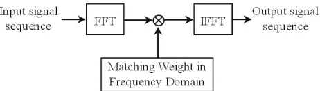
The matched filtering of chirp signal can be completed in the frequency domain by means of Fast Fourier Transform (FFT) [11], and the implementary scheme is shown in Fig. 1. The matching weight is the spectrum of the local chirp signal, which can be calculated beforehand by FFT and stored in the storage of the processing system.
The matching weight coefficients can be expressed as
U(k) =DF T(u∗(−n)) = N−1
X
n=0
u∗(−n)e−j2Nπnk k= 0,1,· · · , N −1 (20)
where * denotes conjugation operation; u∗(−n) = u∗(−nT
s) is the
samples of local chirp signalu∗(−t) with sampling periodT
s; andN is
the length of the sequence.
4.1. Description of the Method Based on Shifting the Matching Weight Coefficients
In order to compensate the range migration between different pulse repetition periods, different matching signals should be used:
v(t) =u(t)e−j2πfb(m)ˆt (21)
wherefb(m) is the introduced frequency component in different periods
for revising the envelope position of the matched filtering output. The output signal of match filtering can be expressed as:
y(ˆt, m) =srI(ˆt, m)⊗v∗(−t)
=
u∗(−t)⊗rect
ˆ
t−t0 TP
·U1·U3·e−j2πfb(m)ˆt
·U2·e−jφ
=
u∗(−t)⊗
rect
ˆ
t−t0 TP
·ej12µ(κ(ˆt−t0)) 2
·ej2πˆt(fd+
1
2πµκκvmT−fb(m))
·U2·e−jφ (22)
where⊗ denotes convolution integration.
Obviously, the condition under which the envelope position of
y(ˆt, m) is independent of m is
fb(m) =
1
2πmµκκvT+fd0 (23)
here, 21πmµκκvT is exactly the frequency item of the MEI. fd0 is
the initial Doppler frequency, which could be determined by apriori information about the target velocity. fd0 has no direct effect on the
It is impossible to storage all potential weight coefficients corresponding to different fb(m). If we quantize fb(m) with 1/N Ts,
then it can be written as:
fb(m) = kb N Ts
or kb = fb(m)
N Ts
kb = 0,1, . . . , M −1 (24)
Formula (24) is an approximate expression of the quantized result. And thenv(t) can be expressed as:
v(t) =u(t)e−jN Ts2π kbt
(25)
According to (20), we have
V(k) =DF T(v∗(−n)) = N−1
X
n=0
u∗(−n)e−j2Nπn(k+kb)=U(k+k
b) (26)
Therefore, V(k) can be obtained by shifting U(k), and doesn’t need to be stored in addition. So we get the method of range migration compensation by shifting the matching weight coefficients, as shown in Fig. 2.
Figure 2. Long time coherent integration with migration compensation by shifting the matching weight coefficients.
4.2. Parasitic Sidelobes and Restraining Method
There exists quantization error when using 1/N Ts to quantize fb(m).
It results in parasitic sidelobes produced in the Doppler domain. This is because the envelopes of the matched filtering output are aligned approximatively, and periodic amplitude modulation to the output in the slow time domain is produced. The position and amplitude of the parasitic sidelobes are related to the velocity of the target. This kind of parasitic sidelobe also exists in the range-bin realignment algorithm and the envelope interpolation algorithm.
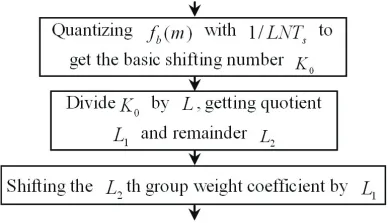
The effectual method to restrain the parasitic sidelobe is to reduce the quantization error. When the sequence length and the sampling period are determined, we can store multi-groups of weight to reduce the quantization error offb(m). Suppose there are Lgroups of weight,
thelth group of weight coefficients can be wrote as:
Vl(k) = N−1
X
n=0
v∗(−n)e−j2Nπn(k+l/L) l= 0,1, . . . , L−1 (27)
Thus, the quantized interval can be turned into 1/LN Ts, which is much
smaller than the frequency interval of the matching weight coefficients. Therefore, we should modify the processing flow of long time coherent integration shown in Fig. 2 by replacing the portion in dashdotted line with the following framework.
Compared with the ordinary algorithm, the above algorithm in Fig. 3 needs much more storage space, which is not the vital bottleneck in signal processing because of the hypergrowth of the digital technique. In practical use, it can get a balance between the hardware expense and the processing performance.
5. SIMULATION RESULTS
The simulation conditions are given as follows: the chirp burst is comprised of 100 pulses with period P RI = 1 ms; the pulse width isTp = 20µs; and the signal bandwidth is 20 MHz. The target velocity
is 640 m/s, and the sampling period of the receiver is 0.025µs.
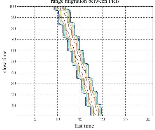
Figure 4 shows the range migration phenomenon of the echo signals in a CPI. It is the amplitude contour map of the planar signal which is the output of the match filtering in the fast time without any compensation. It can be seen that the migration span of the envelope within a CPI reaches about 8 resolution cells. If the signal is coherent integrated directly in the slow time, great loss will be produced as shown in Fig. 5.
Figure 4. Range migration between PRIs without compensation. Figure 5 is the integration result observed in the Doppler dimension. Due to the range-Doppler coupling relationship of the chirp signal, the Doppler migration arises simultaneously with the range migration. In order to reveal the parasitical sidelobe phenomenon of compensation algorithms, the following figures only present the integration result in the Doppler dimension, namely ambiguity velocity dimension.
0 10 20 30 40 50 60 70 0
0.1 0.2 0.3 0.4 0.5 0.6 0.7 0.8 0.9 1
without compensation
normalized voltage
ambiguity velociity
Figure 5. The integratoin output without compensation.
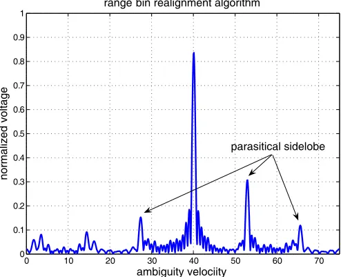
0 10 20 30 40 50 60 70
0 0.1 0.2 0.3 0.4 0.5 0.6 0.7 0.8 0.9 1
range bin realignment algorithm
normalized voltage
ambiguity velociity
parasitical sidelobe
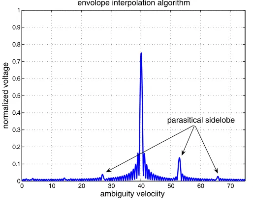
0 10 20 30 40 50 60 70 0
0.1 0.2 0.3 0.4 0.5 0.6 0.7 0.8 0.9 1
envolope interpolation algorithm
normalized voltage
ambiguity velociity
parasitical sidelobe
Figure 7. The integratoin outputs of envelope interpolation algorithm.
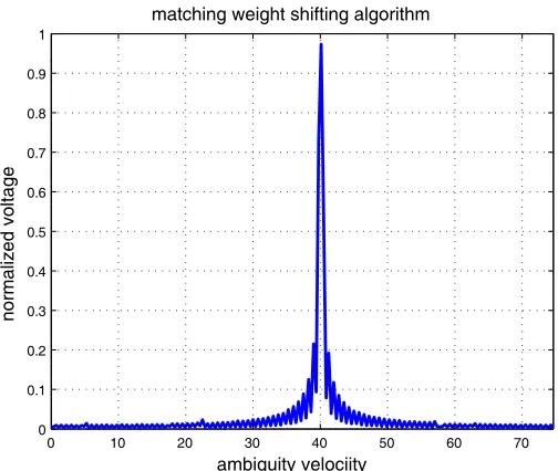
0 10 20 30 40 50 60 70
0 0.1 0.2 0.3 0.4 0.5 0.6 0.7 0.8 0.9 1
normalized voltage
ambiguity velociity matching weight shifting algorithm
parasitical sidelobe
0 10 20 30 40 50 60 70 0
0.1 0.2 0.3 0.4 0.5 0.6 0.7 0.8 0.9 1
normalized voltage
ambiguity velociity matching weight shifting algorithm
Figure 9. The integratoin output of the matching weight shifting algorithm (using 16 groups of weights).
respectively. The integration performance was improved markedly, but unexpected parasitical sidelobes were introduced in the output, which might cause false alarm or sheltering small targets.
Figures 8 and 9 show the results of the matching weight shifting algorithm. It can be seen, by using multi-groups of weight, that the parasitical sidelobes can be restrained effectively, and the integration loss can be further reduced.
6. CONCLUSION
Actually, it is not strictly required that the exact velocity information should be known and the velocity should be constant, because the method has good Doppler resilience, that is to say, when there exists some error about the velocity for compensation, proper integration result can be obtained. When without any priori knowledge of the target velocity, several velocity channels (or Doppler channels) could be set to cover the whole possible scope of the velocity, and each channel compensates the migration according to different velocity.
The proposed algorithm is a method with very low additional computation burden and complexity, which is especially applicable in the coherent integration and detection of high velocity targets in ordinary chirp radar or imaging of moving targets in the wideband radar.
REFERENCES
1. Koo, V. C., Y. K. Chan, and H. T. Chuah, “Multiple phase difference method for real-time SAR autofocus,” Journal of Electromagnetic Waves and Applications, Vol. 20, No. 3, 375–388, 2006.
2. Lim, T. S., V. C. Koo, H. T. Ewe, and H. T. Chuah, “A SAR autofocus algorithm based on particle swarm optimization,” Progress In Electromagnetics Research B, Vol. 1, 159–176, 2008. 3. Park, S. H., H. T. Kim, and K. T. Kim, “Stepped-frequency ISAR
motion compensation using particle swarm optimization with an island model,” Progress In Electromagnetics Research, PIER 85, 25–37, 2008.
4. Chen, C. C. and H. C. Andrews, “Targets motion induced radar imaging,”IEEE Trans. on Aerosp. Electron. Syst., Vol. 16, No. 1, 2–14, 1980.
5. Delisle, G. Y. and H. Wu, “Moving target imaging and trajectory computation using ISAR,” IEEE Trans. Aerosp. Electron. Syst., Vol. 30, No. 3, 887–899, 1994.
6. Perry, R. P., R. C. Dipietro, and R. L. Fante, “SAR imaging of moving targets,”IEEE Trans. on Aerosp. Electron. Syst., Vol. 35, No. 1, 188–200, 1999.
7. Perry, R. P., R. C. Dipietro, and R. L. Fante, “Coherent integration with range migration using keystone formatting,”2007 IEEE Radar Conference, 863–868, 2007.
9. Chen, Y. Z., Y. F. Zhu, H. Z. Zhao, and Q. Fu, “Detection algorithm research of high velocity moving target based on the envelope interpolation,”Signal Processing (China), Vol. 20, No. 4, 387–390, 2004.
10. Ding, L. F. and F. L. Geng, Radar Principle, Xidian University Publishing House, Xi’an, China, 2002.