Compact Varactor-Tuned Bandpass Filter Using
Open Split-Ring Resonators
Cheng Liu, Xinhuai Wang*, Yangbing Xu, and Xiaowei Shi
Abstract—This paper presents a compact tunable bandpass filter that is based on open split ring resonator to achieve high out-of-band rejection. Exact equations and design procedures are given based on strict theoretical analysis. By loading the varactor diodes, the center frequency and bandwidth of the bandpass filter could realize reconfigurable. Then defected ground structure was adopted in the input and output ports for the sake of high out-of-band rejection. In order to verify the result of theoretical analysis, a compact tunable bandpass filter with defected ground structure, whose range of frequency was 1.61 GHz∼1.82 GHz and range of relative bandwidth was 8.3%∼24.8%, had been simulated and fabricated. Good agreement between the measured data and the anticipated results is achieved.
1. INTRODUCTION
Split ring resonators (SRRs) have attracted a lot of attention on the design of BPF with compact dimensions, low insertion loss, low return loss and high out-of-band rejection. The split rings resonator (SRR) is proposed in [1] as a basic particle for the design of artificial negative magnetic permeability media. However, obtaining a bandpass response from a single-layer SRR-based structure seems to be hard to accomplish. A single metal layer metamaterial bandpass filter based on complementary u-shaped resonators (CUSRs) is demonstrated in [2]. A complementary split ring resonators (CRSS) with slots structure, which exhibits a high rejection stop band, is analyzed in [3]. Also the equivalent-circuit model for the CSRR is introduced. To improve the development of planar metamaterial structures, SRRs coupled to planar transmission lines is discussed in [4]. A new LC series element based on a modified version of the SRRs is adopted in [5]. The theory in [6] takes advantage of the small electrical size of SRRs at resonance (typically one tenth of the free space wavelength or less). This feature is related to the large distributed capacitance between the two rings. Incidentally, this allows one to use a simple LCR circuit model to characterize the particle [7]. A metamaterial structure, which combines two open split ring resonators (OSRRs) aligned over the opposing faces of the substrate in an inverted fashion is presented in [8].
Recently, the demands of integrating several applications into single devices and multiple systems have steadily increased, which result in great development of the reconfigurable technique. An electrically small tunable split ring resonator antenna is developed in [9] whose operating frequency can be reduced and tuned. A novel principle for the implementation of tunable split ring resonators is proposed in [10]. An electrically tunable split ring resonators is introduced in [11] and obtained by coupling the SRRs with graphene in terahertz and near-infrared frequency range.
In modern communication system, defected ground structure (DGS) is always put forward to improve the out-of-band rejection of filter and to realize the physical compact dimensions of circuits by taking full advantage of the ground plane. A new DGS for the microstrip line is proposed in [12], which can provide the band gap characteristic in some frequency bands with only one or more unit lattices.
Received 27 June 2014, Accepted 15 September 2014, Scheduled 17 October 2014
* Corresponding author: Xinhuai Wang ([email protected]).
A method to design low-pass filters (LPF) having a DGS and broadened transmission-line elements is adopted in [13]. A novel three-pole coupled-line bandpass filter with a microstrip configuration is shown in [14] that uses DGS sections to simultaneously realize a resonator and an inverter. DGS is realized by etching off defected pattern on the ground plane of 1-D transmission line, which changes the transmission characteristics of the transmission line. Dumbbell-shaped structure is one of the most popular shapes of DGS which generates ultra rejection band beneficial to higher order harmonic suppression [15].
This paper presents a tunable bandpass filter based on OSRR, which has the dumbbell-shaped DGS. The application of the varactor diode and DGS improves the feature of the traditional construction. The essential equivalent circuit model is put forward, and lumped parameters are also extracted for deep insight into the operation mechanism. To demonstrate the validity of the proposed DGS, a lowpass filter using the proposed DGS has been designed and simulated. Besides, in order to verify the result of theoretical analysis, a tunable bandpass filter with DGS, whose range of frequency is 1.61 GHz∼1.82 GHz and range of relative bandwidth 8.3%∼24.8%, has been simulated and fabricated. A satisfactory agreement between the simulated and experimental results of the proposed structure is presented.
2. TOPOLOGY MODEL AND EQUIVALENT CIRCUIT
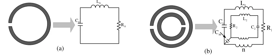
Figure 1 shows the topology model and the equivalent circuit of a single SRR and double SRRs. Single SRR can be equivalent to an inductor L0 and resistor R0 in series combination with the capacitor C0 shown in Fig. 1(a). The outer ring of the double SRRs includes an inductorL1 and resistorR1 in series combination with the capacitorC1, and the inner ring of the double SRRs includes an inductor L2 and resistor R2 in series combination with the capacitor C2 shown in Fig. 1(b). Distinct from the single SRR, the coupling between the two SRRs exists with mutual inductancenand mutual capacitance Cm shown in Fig. 1(b).
1 L
1
C
1 R
2
C
2
R
2
L
n m
C 0
L
0
C
0
R
(a) (b)
Figure 1. Topology model and equivalent circuit of SRRs. (a) Single SRR. (b) Double SRRs.
According to the basic principles of the resonant, we obtain the equations as following formulas:
ωc = 1/
L0C0 (1)
fc = ωc/2·π (2)
where L0: equivalent inductance of the single SRR; C0: equivalent capacitance of the single SRR; ωc: resonant angular frequency of the single SRR; fc: resonant frequency of the single SRR.
Assuming that the coupling between the double SRRs is so weak that they can be ignored, we can obtain the following equations:
ω1 = 1/
L1C1 (3)
ω2 = 1/
L2C2 (4)
where L1: equivalent inductance of the outer ring of the double SRRs; C1: equivalent capacitance of the outer ring of the double SRRs;ω1: resonant angular frequency of the outer ring of the double SRRs;
L2: equivalent inductance of the inner ring of the double SRRs;C2: equivalent capacitance of the inner ring of the double SRRs;ω2: resonant angular frequency of the inner ring of the double SRRs.
particle [7]. The resonance frequency obtained from this model is typically much smaller than that corresponding to the classical ring [16] or square [17] open loop resonators of similar dimensions (λ/2 operation). On the basis of the model demonstrated in Fig. 1(b), OSRR is proposed. The structure and equivalent circuit of OSRR are shown in Fig. 2. To avoid influencing the electromagnetic behaviour of the isolated OSRR, a window is placed on the ground plane. Fig. 2(a) shows the structure of OSRR.rext,
candddefine the dimensions for the OSRR shown in Fig. 2(a). Fig. 2(b) shows the equivalent circuit of OSRR. Among the equivalent circuit,εef represents the effective permittivity of the transmission lines.
Zorepresents the characteristic impedance of the transmission lines. The resistanceR, inductanceLand capacitor C represent the equivalent resistance, inductance and capacitance of the OSRR, respectively. The bandwidth of the filter can be controlled by adjusting the length ofd. Seeing the equivalent circuit, we obtain the equations as following formulas:
ω = 1/√LC (5)
f = ω/2·π (6)
where L: equivalent inductance of the OSRR; C: equivalent capacitance of the OSRR; ω: resonant angular frequency of the OSRR;f: resonant frequency of the OSRR.
ext
r ro
c d
R
L
CZ
o εefd
Z
o ef(a) (b)
ε
,
,
Figure 2. Structure and equivalent circuit of OSRR. (a) Structure. (b) Equivalent circuit.
L
C Zo
Zo
(a) (b)
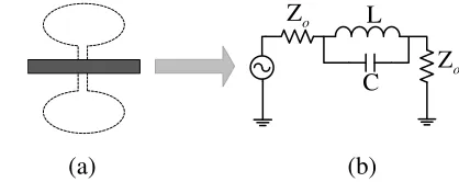
Figure 3. Structure and equivalent circuit of DGS. (a) Structure. (b) Equivalent circuit.
To improve the high selectivity and high out-of-band rejection in modern communication systems, DGS is adopted in the input and output ports. Fig. 3 shows the conformation and equivalent circuit. It is a simple resonator whereL and C are the equivalent inductance and equivalent inductance of the resonator. High selectivity and high out-of-band rejection usually can be achieved by increasing the number of DGS resonators. High out-of-band rejection was realized by using several dumbbell-shaped DGSs introduced in [15].
To realize reconfigurable bandwidth and center frequency, the construction introduces the varactor diodes to change the length of the transmission lines connecting the OSRR [18]. DGS is adopted in the input and output ports for the sake of intense and high out-of-band rejection.
3. SIMULATION AND MEASUREMENT
In order to validate the proposed model, we have fabricated the bandpass-filter and compared the frequency response measured by a vector network analyzer with the results of simulation obtained by HFSS. SMV1405, whose tunable range of capacitance is Cr = 0.5 ∼ 2.67 pF for varying DC voltages in the interval 0–30 V, is applied to this construction. The structure has been fabricated on a Rogers F4B-2 substrate.
Figure 4 shows the model of varactor-tuned bandpass filter, where the deep colour parts represent the microstrip line, and the light colour parts represents the ground plane. Moreover, other parts are the biasing circuit, where we can change the bandwidth and center frequency. The input characteristic impedance and output characteristic impedance are designed for 50 Ω. Applying the basic theory in [6, 7] and [16, 17], we designed tunable bandpass filter.
Table 1 shows the designed parameters of the proposed model.
ext
r ro
c d
w C1 C1 w
2
R R2
t
D
t
D
1
w w1
2
l
1
l
Figure 4. The model of varactor-tuned bandpass filter.
Table 1. Designed parameters of the proposed model.
Name l1 l2 w w1 r0 rext c d
Size (mm) 13.5 12 1.38 0.6 2.8 3.6 0.4 0.4
(a) (b)
Figure 5. Designed model and Simulation of DGS. (a) Designed model. (b) Simulated results.
In order to protect the varactor-tuned, two 200 Ω resistances are designed into the model. Fig. 6 shows the top and bottom views of the fabricated varactor-tuned bandpass filter using open split-ring resonators.
(a) (b)
Figure 6. Fabricated the OSRR. (a) Top view. (b) Bottom view.
(a) (b)
(c) (d)
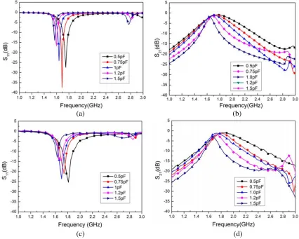
Figure 7. Simulated and measured results of return loss S11 and insertion loss S21. (a) Simulation of return loss S11. (b) Simulation of insertion loss S21. (c) Measurement of return loss S11. (d) Measurement of insertion lossS21.
Figs. 7(c)–(d), with the range of frequency 1.61 GHz ∼1.82 GHz and the range of relative bandwidth 8.3%∼24.8%. Return loss is more than 12.5 dB and insertion loss less than 2.5 dB. From the simulated and measured results, we can see that the center frequency and bandwidth decrease gradually with the increase of equivalent capacitor value Cr. When the equivalent capacitor value Cr increases, the capacitor C and equivalent length d of the OSRR increase, so the center frequency and bandwidth decrease [16, 17]. Also the min. S21 (dB) in Fig. 7(d) fluctuates with the capacitances for the series resistances of the varactors as studied and reported in [18].
4. CONCLUSIONS
In this paper, a compact varactor-tuned bandpass filter using open split-ring resonators has been designed, fabricated and measured. Compared to conventional OSRR implementations, the cell has provided more flexibility to synthesize frequency responses with controllable bandwidth and high out-of-band rejection. As a result, the full-wave simulations agree well with the measurements.
ACKNOWLEDGMENT
REFERENCES
1. Pendry, J. B., A. J. Holden, D. J. Robbins, and W. J. Stewart, “Magnetism from conductors and enhanced nonlinear phenomena,” IEEE Transactions on Microwave Theory and Techniques, Vol. 47, 2075–2084, 1999.
2. Al-Naib, I. A. I., C. Jansen, and M. Koch, “Single metal layer CPW metamaterial band pass filter,”
Progress In Electromagnetics Research Letters, Vol. 17, 153–161, 2010.
3. Ibraheem, I. A. and M. Koch, “Coplanar waveguide metamaterials: The role of bandwidth modifying slots,” Applied Physics Letters, Vol. 91, 113517-113517–3, 2007.
4. Baena, J. D., J. Bonache, F. Martin, R. M. Sillero, F. Falcone, T. Lopetegi, et al., “Equivalent-circuit models for split-ring resonators and complementary split-ring resonators coupled to planar transmission lines,”IEEE Transactions on Microwave Theory and Techniques, Vol. 53, 1451–1461, 2005.
5. Martel, J., R. Marqu´es, J. D. Baena, F. Mart´ın, and M. Sorolla, “A new LC series element for compact bandpass filter design,”IEEE Microwave and Wireless Components Letters, Vol. 14, No. 5, May 2004.
6. Marques, R., J. Martel, F. Mesa, and F. Medina, “Left-handed-media simulation and transmission of EM waves in subwavelength split-ring-resonator-loaded metallic waveguides,” Physical Review Letters, Vol. 89, 183901-1, Oct. 28, 2002.
7. Marques, R., F. Mesa, J. Martel, and F. Medina, “Comparative analysis of edge- and broadside-coupled split ring resonators for metamaterial design — Theory and experiments,” IEEE Transactions on Antennas and Propagation, Vol. 51, 2572–2581, 2003.
8. De Dios Ruiz, J. and J. Hinojosa, “Double-sided open split ring resonator for compact microstrip band-pass filter design,”IET Microwaves, Antennas &Propagation, Vol. 6, 846–853, 2012. 9. Shaozhen, Z., D. G. Holtby, K. L. Ford, A. Tennant, and R. J. Langley, “Compact low frequency
varactor loaded tunable SRR antenna,”IEEE Transactions on Antennas and Propagation, Vol. 61, 2301–2304, 2013.
10. Bouyge, D., D. Mardivirin, J. Bonache, A. Crunteanu, A. Pothier, M. Duran-Sindreu, et al., “Split ring resonators (SRRs) based on micro-electro-mechanical deflectable cantilever-type rings: Application to tunable stopband filters,” IEEE Microwave and Wireless Components Letters, Vol. 21, 243–245, 2011.
11. Vasic, B., M. M. Jakovljevic, G. Isic, and R. Gajic, “Tunable metamaterials based on split ring resonators and doped graphene,” Applied Physics Letters, Vol. 103, 011102-011102–4, 2013. 12. Dal, A., P. Jun-Seok, K. Chul-Soo, K. Juno, Q. Yongxi, and T. Itoh, “A design of the low-pass filter
using the novel microstrip defected ground structure,” IEEE Transactions on Microwave Theory and Techniques, Vol. 49, 86–93, 2001.
13. Jong-Sik, L., K. Chul-Soo, A. Dal, Y.-C. Jeong, and N. Sangwook, “Design of low-pass filters using defected ground structure,” IEEE Transactions on Microwave Theory and Techniques, Vol. 53, 2539–2545, 2005.
14. Jun-Seok, P., Y. Jun-Sik, and A. Dal, “A design of the novel coupled-line bandpass filter using defected ground structure with wide stopband performance,” IEEE Transactions on Microwave Theory and Techniques, Vol. 50, 2037–2043, 2002.
15. Safwat, A. M. E., F. Podevin, P. Ferrari, and A. Vilcot, “Tunable bandstop defected ground structure resonator using reconfigurable dumbbell-shaped coplanar waveguide,”IEEE Transactions on Microwave Theory and Techniques, Vol. 54, 3559–3564, 2006.
16. Wolff, I., “Microstrip bandpass filter using degenerate modes of a microstrip ring resonator,”
Electronics Letters, Vol. 8, 302–303, 1972.
17. Hong, J.-S. and M. J. Lancaster, “Couplings of microstrip square open-loop resonators for cross-coupled planar microwave filters,” IEEE Transactions on Microwave Theory and Techniques, Vol. 44, 2099–2109, 1996.