Available online: https://edupediapublications.org/journals/index.php/IJR/ P a g e | 1334
Three-Level Rectifiers in Wind Turbine Systems Open-Circuit Fault-Tolerant
Control for Outer Switches
Jagruthi Petrum
1Assistant Professor with the Department of Electrical & Electronics Engineering at Dadi Institute of Engineering and
Technology, JNT University, Kakinada, Andhra Pradesh, India, E-mail id ([email protected])
Abstract
- The proposed tolerant control maintainsnormal operation with sinusoidal currents under the open-circuit fault of outer switches by adding a compensation value to the reference voltages. A three-level converter is used as the power converters of wind turbine systems because of their advantages such as low-current total harmonic distortion, high efficiency, and low collector– emitter voltage. Interior permanent magnet synchronous generators (IPMSGs) have been chosen as the generator in wind turbine systems owing to their advantages of size and efficiency. In wind turbine systems consisting of the three-level converter and the IPMSG, fault-tolerant controls for an open-circuit fault of switches should be implemented to improve reliability. This paper focuses on the open-circuit fault of outer switches (Sx1 and Sx4 ) in three level rectifiers (both neutral-point clamped and T-type) that are connected to the IPMSG. In addition, the effects of Sx1 and Sx4 open-circuit faults are analyzed, and based on this analysis, a tolerant control is proposed. The effectiveness and performance of the proposed tolerant control are verified by simulation
IndexTerms—Neutral-point-clamped rectifier, open-circuit fault, open-switch fault, reliability, three-level topology, tolerant control, T-type rectifier.
NOMENCLATURE pf Power factor.
\Irec Rectifier input current.
I x,rec Rectifier input current of x-phase.
Vrec Rectifier input voltage.
V x,rec Rectifier input voltage of x-phase. VEMF Back EMF of PMSG.
ϕZ Phase difference (°) between VEMF and Vrec.
Φpf Phase difference (°) between Iref and VEMF.
V x ,ref Reference voltage of x-phase.
V mag Magnitude of the reference voltages.
fs Fundamental frequency (Hz) represented the angularfrequency of the PMSG.
Vref,max, Maximum and minimum values of Va,ref
Vref,min Vb,ref , and Vc,ref .
V comp Compensation voltage of the proposed tolerant control.
R Equivalent resistance (Ω) of the PMSG.
L Equivalent inductance (H) of the PMSG.
I qe,Ide d-axis and q-axis currents in the d–q synchronous rotating frame.
θEMF VEMF’s angle.
Ma Modulation index, √3 × Vmag/Vdc.
I. INTRODUCTION
Improve the reliability of wind turbine systems. Switch
faults are divided into a short-circuit fault and an open-circuit fault [12]. The short-open-circuit fault normally leads to a breakdown of the entire system; therefore, faultdetection and tolerant control
methods for the short-circuit fault require additional circuits. On the other hand, the open-circuit fault leads to current distortion, which can lead to a breakdown if it persists for a long time; therefore, the open-circuit fault
should be detected, and the
tolerant controls are necessary [9]. In wind turbine systems, a back-to-back converter is used to transfer power from the generator to the grid. A back-toback converter using the 3L-NPC topology The power capacity of a wind turbine system has been increasing consistently, leading to the development of generators with large power capacity [1]–[3]. There are many types of generators. Permanent magnet synchronous generators (PMSGs) have high efficiency and high reliability compared with induction generators. This is because external excitation is not required and there are no copper losses in the rotor circuits. Moreover, because of the smaller size of the PMSG, the weight of the wind turbine is reduced [4]. Among various PMSGs, interior PMSGs (IPMSGs) are especially advantageous from the standpoints of efficiency and power generation owing to the use of the reluctance torque [4]–[7]. Generators requiring high voltage need to use multilevel converter topologies to reduce the collector–emitter voltage per switch. Among multilevel topologies, three-level topologies such as the three-level
neutral-point clamped (3L-NPC) and
Available online: https://edupediapublications.org/journals/index.php/IJR/ P a g e | 1335 (THD) in comparison with the two level topology [8]. The
3L-NPC topology is vulnerable to switch faults because many switches are used. Switch fault detection and tolerant control methods for switch faults should be implemented to improve the reliability of wind turbine systems. Switch faults are divided into a short-circuit fault and an open-circuit fault The short-circuit fault normally leads to a breakdown of the entire system; therefore, fault detection and tolerant control methods for the short-circuit fault require additional circuits. On the other hand, the open-circuit fault leads to current distortion, which can lead to a breakdown if it persists for a long time; therefore, the open-circuit fault should be detected, and the tolerant controls are necessary [9]. In wind turbine systems, a back-to-back converter is used to transfer power from the generator to the grid. A back-to-back converter using the 3L-NPC topology is shown in Fig. 1.
Fig. 1. Back-to-back converter using the 3L-NPC topology in wind turbine systems.
This consists of the machine-side 3L-NPC rectifier, the dc-link, and the grid-side 3L-NPC inverter. Depending on the operating conditions, tolerant controls can be applied for the rectifier or the inverter because the current paths of
the rectifier and the
inverter are different [9]. In addition, the different structure of the three-level topologies should be considered in the tolerant controls [9]. In the 3L-NPC inverter, the open-circuit fault of the inner switch causes the outer switch connected it to be infeasible; therefore, changing only the switching method does not become a solution for the open-circuit fault, and the additional devices such as fuses and switches should be added for achieving the tolerant operation under the open-circuit fault of the inner switch . However, the open-circuit fault of the outer switch can be handled by changed the switching method in limited rang, the tolerant control
method limits
the output voltage range by half. In the 3L-NPC rectifier, the current distortion caused by the open-circuit fault of the inner switch can be restored partially by clamping the switching state without any additional devices [2]. In addition, the reactive current is injected to eliminate current distortion caused by the open-circuit fault of the
outer switch [2]. This method can also be applied for the T-type rectifier. The T-type rectifier is advantageous on the tolerant control because the switches in a leg are independent of each other. this control method injects the exact reactive current required to eliminate the current distortion. This means that the pf is changed. Rectifiers with IPMSGs can operate to generate maximum power at pfs other than unity. IPMSGs provide more power Many tolerant control methods for the open-circuit fault of the inner switch, which can be used in both the T-type inverter and rectifier, were proposed in [3], [4], and [2]–[5]. These methods change the switching method to disable the switch with the open-circuit fault and do not need the additional devices. This paper focuses on the open-circuit fault of the machine side 3L-NPC rectifier. In general, the input currents of the 3LNPC rectifier do not flow through the outer switches (Sx1 and Sx4) at unity power factor (pf); therefore, the existing tolerant controls for the 3L-NPC rectifier take into account only the inner switches (Sx2 and Sx3) [3]. However, according to the specification of the PMSG, an open-circuit fault of the outer switch can cause current distortion as much as when an open circuit fault of the inner switch occurs [2]. The tolerant control for Sx1 and Sx4 open-circuit faults is also proposed
Fig. 2. Current paths depending on the
current direction and the switching state.
when rectifiers operate at a unique pf [4]–[7]. In such a case, an open-circuit fault of the outer switches (Sx1 and
Sx4) causes current distortion and torque fluctuation, which can lead to vibration of the wind turbine. In this
paper, the reason for the
current distortion caused by the outer switches (Sx1 and
Available online: https://edupediapublications.org/journals/index.php/IJR/ P a g e | 1336 proposed. In the proposed tolerant control, the switch with
an open-circuit fault
is not used to generate the input voltages of the three-level rectifier by adding a compensation value to the reference voltages. The compensation value is simply calculated and the pf does not change in the proposed tolerant control. The performance of the proposed tolerance control is proved by simulation.
II. OPEN-CIRCUIT FAULT ANALYSIS OF OUTER SWITCHES
There are three switching states (P, N, and O) in the 3L-NPC rectifier [9]. Six current paths can be generated depending on the current direction and the switching state, and these are shown in Fig. 2 [3]. Fig. 3 shows the input current generation process of a rectifier with unity pf. The rectifier current is Irec, the rectifier voltage is Vrec, and the back electromotive force (EMF) is VEMF. The
Fig. 3. Rectifier operation at unity pf TABLE I
CURRENT PATH COMPOSITION DEPENDING ON THE PART OF FIG. 3
The current continuously flows through two diodes if the switching state is changed to P or N switching state in which no current flows through the switches. In parts B and D, the P and N switching stages are the valid switching state where the current flows through the switches. Phase difference between VEMF and Vrec, which causes the current flow, is controlled to match the phase of Irec up with the phase of the corresponding
VEMF. One period of Irec can be divided into four parts depending on the polarity of Irec and Vrec. The generated current paths are different depending on the part, and these are summarized in Table I. In parts A and C, the O switching state causes the input current flow; therefore, this is called the valid switching state. When the rectifier
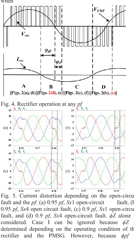
operates with unity pf, parts A and C are large, and parts B and D are small. If parts B and C are very small as much as be ignored, the Sx1 and Sx4 open-circuit faults can be ignored [22], [23]. However, parts B and D can be extended in Case I when VEMF is small and a large Irec is required [22]. This is because the phase difference between VEMF and Vrec becomes large. In
this paper, the other case (Case II), which is the reactive current injection for IPMSG, is also considered. Fig. 4 shows that the input current generation process of the rectifier for Cases I and II. There are two phase differences: the phase difference (ϕZ ) between VEMF and
Vrec explained in [22], and the phase difference (ϕpf ) between Iref and VEMF caused by the pf. In Fig. 4, part B (or part D) consists of ϕZ and ϕpf , and their lengths increase. This means that the current can be more distorted by the open-circuit fault of the outer switches compared to when
Fig. 4. Rectifier operation at any pf
Available online: https://edupediapublications.org/journals/index.php/IJR/ P a g e | 1337 determined by the pf, Case II should be considered when
the IPMSG is employed.
The current distortion caused by the open-circuit fault of the outer switches is shown in Fig. 5 for various pfs. Owing to the infeasible open-circuit fault switch, the current becomes zero during the range consisting of ϕZ
and ϕpf . The Sx1 open-circuit fault makes the current path of Fig. 2(d) infeasible. The current path of Fig. 2(d) belongs to part B; therefore, the Sx1 open circuit fault causes distortion in the negative current as shown in Fig. 5(a) and (c). On the contrary, the Sx4 open-circuit fault leads to distortion in the positive current as shown in Fig. 5(b) and (d) because the current path of Fig. 2(c) related to the Sx4 open-circuit fault belongs to part D. The low pf
has a large ϕpf . Therefore, the rectifier operation at a low
pf leads to a large zero-current range when the open circuit fault of the outer switch occurs. As a result, the zero current range increases, as the pf decreases. The analysis related to the open-circuit fault of the outer switches can be applied to the T-type topology. The effects of open-circuit faults of the outer switches on the current are the same in both the NPC rectifier and the T type rectifier [3], [2]. Therefore, the current distortion caused by open-circuit faults of the outer switches in the NPC rectifier is the same as that in the T-type rectifier.
III. TOLERANT CONTROL FOR OPEN-CIRCUIT FAULT OF OUTER SWITCHES
This method changes the phase of Irec so that it corresponds with the phase of Vrec. This means that parts B and D are eliminated. An existing tolerant control method for the open-circuit fault of the outer switches is reactive current injection [2]. However, this tolerant control method has the disadvantage of low-power generation efficiency of the generator because the PMSG has efficient operating condition which depends on the pf
of the rectifier. In general, the unity pf is required for the best operating condition of a surface PMSG. The best operating condition of an IPMSG does not correspond to the unity pf, and this is determined by the specifications of the IPMSG. The proposed tolerant control does not change the pf of the rectifier. The rectifier voltage (Vrec) without the current path related to the open-circuit fault switch is generated by changing the reference voltages. To explain the proposed tolerant control, the Sx1 open-circuit fault is used as an example.
A. Compensation Voltage (Vcomp) Calculation
In the proposed tolerant control, a reference voltage of a phase containing the Sx1 Fig. 6. Change of reference voltages in the proposed tolerant control for the Sx1 open-circuit fault (0.95 pf). open-circuit fault is changed to zero as shown in Fig. 6. is the fundamental frequency. The offset voltage (Voffset) is added to each reference voltage
to expand the range of the modulation index (Ma = √3 × V
mag/Vdc). Voffset and the changed reference voltages (Vx,ref,offset, x = a, b, c) are expressed as
Voffset = -(Vref,max + Vref,min)/2, (2)
V a,ref,offset = Va,ref + Voffset
Vb,ref,offset = Vb,ref + Voffset V c,ref,offset = Vb,ref + Voffset (3) where Vref,max and Vref,min are the maximum and minimum values of V a,ref , Vb,ref , and Vc,ref . The reference voltages of (3) are compared with the carrier
signals to generate Vrec.
When the Sx1 open-circuit fault occurs, the current path of Fig. 2(d) should be eliminated to prevent current distortion; therefore, the reference voltage should be changed to generate Vrec without the current path of Fig.
2(d). As a
result, the current path of Fig. 2(d) disappears because the O switching state is only used in part B. To make the reference voltage zero, |Vcomp| is assigned the magnitude of the reference voltage (Vx,ref,offset) containing the
open-circuit fault, and
V comp can be expressed as
V comp = -Vx,ref,offset(x = a phase containing open
-circuited fault switch). (4)
The proposed tolerant control is implemented by adding V
comp to the reference voltages (Vx,ref,offset, x = a, b, c). The
new reference voltages (Vx,ref,tolerance, x = a, b, c) of the proposed tolerant control are expressed as
V c,ref,tolerance = Vb,ref,offset + Vcomp. (5)
B. Compensation Range for Adding Vcomp By adding Vcomp to each reference voltage, the use of the current path related to the open-circuit fault switch will be precluded. To achieve this perfectly, Vcomp is added for the suitable range and position. The compensation range, which is part B or part D of Fig. 4, consists of ϕZ and ϕpf .
ϕZ can be calculated with the equivalent circuit of the PMSG and the three-level rectifier [22]. ϕZ , which is the phase difference between VEMF and Vrec, is expressed as
ϕZ = tan-1 - | VEMF Irec| × - |I2ref πf|sRL (6) where R
and L are the equivalent resistance and inductance of the PMSG, and fs is the fundamental frequency representing the angular frequency of the PMSG. ϕpf , which is the phase difference between VEMF and Irec, is related to the
Available online: https://edupediapublications.org/journals/index.php/IJR/ P a g e | 1338 Fig. 7. Compensation position on the basis of VEM F ’s
angle (θEM F ).
expressed as ϕpf = cos-1(pf). (7) If the d–q control theorem is used, ϕpf can be calculated as
ϕpf = cos-1 ⎛ ⎝Iqe 2Iqe + Ide 2 ⎞ ⎠ , (8) where Ide
indicates the d-axis current related to the flux and Iqe
indicates the q-axis current related to the torque, and these are values in the d–q synchronous rotating frame. ϕZ
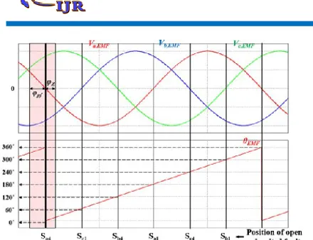
andϕpf , which are calculated from (6) and (8), are located near the zero-crossing point of VEMF as shown in Fig. 6. Therefore, the compensation position for adding Vcomp is
defined on
the basis of VEMF’s angle (θEMF). Fig. 7 shows three-phase VEMFs and θEMF. θEMF is acquired from the encoder or position sensor. Six zero-crossing points are
expressed for every 60°,
which are matched to each open-circuit fault as shown in Fig. 7. Consequently, θEMF representing each zero-crossing point is a criterion for adding Vcomp. For example, when the Sa1 open circuit fault occurs, Vcomp should be added for the compensation range from (0◦ - ϕpf ) to (0◦ + ϕZ ) which is based on 0°. By considering all open-circuit faults, Table II shows the compensation ranges for eliminating the current distortion depending on the position of the open-circuit fault.
Fig. 8. Proposed tolerant control considering neutral-point voltage balance under the Sa1 open-circuit fault.
C. Considering Neutral-Point Voltage Balance
The compensation voltage which is one of the offset voltages can cause neutral-point voltage unbalance because Vcomp calculated from (4) is a one-sided voltage [1], [4]. Therefore, two dc-link capacitors have different
values depending on
the polarity of Vcomp generated for the open-circuit fault. The neutral-point voltage unbalance increases the voltage stress on the switch and the current THD [24]. The proposed tolerant control for the open-circuit fault of the outer switches has to incorporate a solution for the neutral point voltage unbalance problem. Therefore, as mentioned earlier, Vcomp is added for the corresponding compensation position depending on the position of the open-circuit fault, and then, Vcomp is also added in the diametrically opposite compensation position to balance the neutral-point voltage. Two Vcomps added in two positions have opposite polarity, and this results in the balanced neutral-point voltage. The final principles of the proposed tolerant control with the neutral-point voltage balance are summarized in Table III. Fig. 8 shows the concept of proposed tolerant control considering the neutral-point voltage balance when the
Sa1 open-circuit fault occurs. In Fig. 8, Vcomp is added for the compensation range [(0◦ - ϕpf ) ∼(0◦ + ϕZ)] which corresponds to the position for the Sa1 open-circuit fault; in addition, Vcomp is also added for the diametrically opposite compensation range [(180◦ - ϕpf ) ∼(180◦ + ϕZ
)], which is the range for the Sa4 open-circuit fault.
Fig. 9. Vx,ref,tolerance (x = a,b,c) and Vcom p depending on the pf when Ma is 0.5.
Fig. 10. Applicable pf range of the proposed tolerant control depending on Ma .
Available online: https://edupediapublications.org/journals/index.php/IJR/ P a g e | 1339
V x,ref,tolerance cannot exceed a limitation voltage (Vlimit), which is restricted by the dc-link voltage (Vdc). Therefore,Vcomp is limited as follows:
Vcomp < Vlimit - Vref,max (9) where Vlimit is Vdc/2. On the basis of (9), the applicable operation range of the proposed tolerant control is determined depending on Ma
and the pf. Fig. 9 shows Vx,ref,tolerance and Vcomp of the proposed tolerant control depending on the pf when Ma is 0.5. In Fig. 9, Vcomp leads to V a,ref,tolerance with zero value in the corresponding compensation range. Moreover, the peak value of Vc,ref,tolerance increases owing to
Vcomp. As the pf decreases, this peak value increases; however, it does not exceed Vlimit. Consequently, when Ma is smaller than 0.5, Vcomp can be added regardless of the pf because Vc,ref,tolerance cannot
exceed Vlimit. When Ma
is larger than 0.5, the applicable pf range is determined by
Ma.
This is because a low Ma provides a large margin for
Vcomp; however, a large Vcomp cannot be acceptable for high Ma. Fig. 10 shows the applicable pf range for various values ofMa. The shaded part of Fig. 10 represents the applicable operation range. The proposed tolerant control
is feasible over the entire
factor range when Ma is smaller than 0.5. By increasing
Ma from 0.5, the applicable operation range decreases. In Fig. 10
Fig. 11. Simulation results with the proposed tolerant control under the Sa1 open-circuit fault (600 rpm, Ma = 0.35, 0.95 pf)
Available online: https://edupediapublications.org/journals/index.php/IJR/ P a g e | 1340 Fig. 13. Simulation results with the proposed tolerant
control under the Sa1 open-circuit fault (1000 rpm, Ma = 0.59, 0.95 pf)
IV. SIMULATION RESULTS
The simulation is performed using the PSIM tool. The 3L-NPC rectifier of the back-to back converter with 2.5-MW IPMSG is only considered in the simulation. pfs and generator speeds. of the PMSG is 600 rpm, Ma is 0.35, and the pf of the rectifier is 0.95. Owing to the Sa1 open-circuit fault, the negative current is distorted as shown in Fig. 11(a). After the reference voltages are changed by
Vcomp for the corresponding ranges [(0◦ - ϕpf ) ∼ (0◦ +
ϕZ ),(180◦ - ϕpf ) ∼ (180◦ + ϕZ )] which are defined in Table III. As a result, the a-phase pole voltage (Van) is clamped to 0 at their ranges as shown in Fig. 11(b) and the current distortion is eliminated completely. In addition, the two dc-link capacitor voltages are balanced. The simulation parameters are as follows: the switching frequency is 2 kHz, the control period is 250 μs, the dc-link capacitor is 35 mF, and the dc-link voltage is 1200 V. The IPMSG parameters used in the simulation are shown in Table IV. The proposed tolerant control for the open-circuit fault of the outer switches (Sx1,Sx4) is implemented for different The proposed tolerant control is effective for the pf transition operation of the rectifier. Fig. 12 shows the results when the proposed tolerant control is applied and the pf is changed from 0.95 to 0.9. The compensation the pf
decreases and the currents are maintained without distortion continuously. Moreover, we know that the peak value of V c,ref,tolerance becomes large because the pf
decreases which was discussed in Section III. The proposed tolerant control is applied. The current THD is increased by the Sa1 open-circuit fault; however, owing to the proposed tolerant control, the current THD is restored
as good
as normal state without any open-circuit fault.
VI.CONCLUSION
This paper proposes a tolerant control for the open-circuit fault of the outer switches in three-level rectifiers (both 3L-NPC and T-type topologies) used in wind turbine systems This control is implemented by adding a compensation voltage (Vcomp) to the reference voltages for the corresponding compensation ranges depending on the position of the open-circuit fault. Furthermore, this control can be used in both the 3L-NPC. The reason why the tolerant control for the open-circuit fault of the outer switches in three-level rectifiers is necessary is presented, together with the supporting circuit analysis. and T-type rectifiers and guarantees normal operation without a change of the pf in the applicable operation range shown in Fig. 10 depending on the modulation index (Ma) and the pf. Although the operating range of the proposed
tolerant control is subject to a limitation, not always operate with the rated wind speed and that the operating pf
of the rectifier with an IPMSG is not too low, the proposed tolerant control is clearly effective. The performance and of the proposed tolerance control are simulations.
REFERENCES
[1] A. Isidori, F. M. Rossi, F. Blaabjerg, and K. Ma, “Thermal loading and reliability of 10-MW multilevel wind power
converter at different wind
roughness classes,” IEEE Trans. Ind. Appl., vol. 50, no. 1, pp. 484–494, Jan./Feb. 2014.
[2] H. G. Jeong, K. B. Lee, S. Chio, and W. Choi, “Performance improvement of LCL-filter-based grid-connected inverters using PQR power transformation,” IEEE Trans. Power Electron., vol. 25, no. 5, pp. 1320–1330, May 2010.
[3] S. Li, T. A. Haskew, R. P. Swatloski, and W. Gathings, “Optimal and direct-current vector control of direct-driven PMSG wind turbines,” IEEE Trans. Power Electron., vol. 27, no.
5, pp. 2325–2337, May 2012.
[4] W. Qiao, L. Qu, and R. G. Harley, “Control of IPM synchronous generator for maximum wind power generation
considering magnetic saturation,”
IEEE Trans. Ind. Appl., vol. 45, no. 3, pp. 1095–1105, May/Jun.
2009.
[5] S. Morimoto, H. Nakayama, M. Sanada, and Y. Takeda, “Sensorless output maximization control for variable-speed wind generation system using IPMSG,” IEEE Trans. Ind. Appl., vol.
41, no. 1, pp. 60–67, Jan./Feb. 2005.
[6] Y. Zhao, W. Qiao, and L. Wu, “An adaptive quasi-sliding-mode rotor position observer-based sensorless control for interior
permanent magnet
synchronous machines,” IEEE Trans. Power Electron., vol. 28,
no. 12, pp. 5618–5629, Dec. 2013.
[7] P. B. Reddy, A. M. EL-Refaie, and K. K. Huh, “Effect of number of layers on performance of fractional-slot
concentrated-windings interior
permanent magnet machines,” IEEE Trans. Power Electron., vol.
30, no. 4, pp. 2205–2218, Apr. 2015.
[8] J. S. Lee and K. B. Lee, “New modulation techniques for a leakage current reduction and a neutral-point voltage balance in transformerless
photovoltaic systems using a three-level inverter,” IEEE Trans.
Power Electron., vol. 29, no. 4, pp. 1720–1732, Apr. 2014.
[9] U. M. Choi, H. G. Jeong, K. B. Lee, and F. Blaabjerg, “Method for detecting an open-switch fault in a grid-connected NPC inverter system,” IEEE Trans. Power Electron., vol. 27, no. 6, pp. 2726–2739, Jun. 2012.
[10] U. M. Choi, J. S. Lee, and K. B. Lee, “New modulation strategy to balance the neutral-point voltage for three-level neutral-clamped inverter systems,” IEEE Trans. Energy