BAND STRUCTURES AND ABNORMAL BEHAVIOR OF ONE DIMENSIONAL PHOTONIC CRYSTAL CONTAINING NEGATIVE INDEX MATERIALS
G. N. Pandey
Department of Physics Anand Engineering College Agra-282007 (UP),India
K. B. Thapa
Department of Physics
University Institute of Engineering & Technology Chhatrapati Sahu Ji Maharaj University
Kanpur-208024,India
S. K. Srivastava
Department of Physics
Amity Institute of Applied Sciences (AIAS) Amity University
Noida,Sector-125,India
S. P. Ojha
Chaudhari Charan Singh University Meerut-200005,India
materials can be used to trap the photons inside the PC i.e.,light localization occurs without introducing the defects.
1. INTRODUCTION
The artificial micro-structured materials with a periodically modulated dielectric functions are known as photonic crystals (PCs). Intensive investigations on PCs have been carried out since the idea of PCs was proposed [1,2]. Up to now, most calculations of the photonic band structures and the corresponding electric/magnetic field distributions have been performed based on numerical methods,such as the plane wave expansion method and the finite difference time domain method [3,4]. Some qualitative conclusions have been derived from the related numerical analysis. It is well known that the exact analytical solutions are quite useful for us to understand the physics of PCs. In a sense,the simplest one-dimensional (1D) PC with Kronig-Penney periodic dielectric structure [5,6] is the only exactly solvable theoretical model. The purpose is to draw new physics out of the 1-D PC by means of the exact analytical solutions.
an over-screened,under-damped response due to the structural resonances. A negative refractive index is obtained by interleaving two structures that individually show a negativeεor negativeµ. Zhang et al. [15] has calculated the photon tunneling via evanescent fields in the presence of a layer of negative refraction material in contrast to the conventional right-handed materials. They have shown that photon is tunneled through a much greater distance when a NIM has same magnitude of refraction index and thickness as those of the positive index material. Wu et al. [16] have shown the dispersion relation of one-dimensional periodic structure with alternate positive index material (PIM) and negative index material (NIM). The periodic structure has described unusual phenomena such as spurious modes with complex frequencies,discrete modes and photon tunneling modes. Jiang et al. [17] have studied the transmission properties of a one-dimensional photonic crystal containing two kinds of single negative media. This structure can posses a type of photonic band gap with zero effective phase (φeff). The zero-φeff gap distinguishes itself from a Bragg gap
in that it is invariant with a change of scale length and is insensitive to thickness fluctuation. Baria et al. [18] have investigated the band structures of one-dimensional superlattices composed of right handed materials and left handed materials. It is shown that such structures can exhibit new type of electromagnetic modes and dispersion curve that do not exist in usual superlattices composed only by right handed materials. With an appropriate choice of parameters,such band structure is possible to realize an absolute band gap for both TE and TM polarization; this proposed an omni-directional reflection of light for both polarizations. The complete band gap in one-dimensional left handed periodic structures has been purposed. The modulation of refractive index in all three spatial directions is required to find a complete band gap and prevent the propagation of electromagnetic waves in all directions [19–21]. Singh et al. [22] have investigated the structural parameters for the formation of omni-directional band gaps in one dimensional photonic crystal. The omni-directional band gaps are increased with increasing the parameters of refractive index contrast and filling fraction. They have found that the omni-directional reflection ranges of the Si-SiO2 periodic system is gone to a maximum
defect. With suitable parameters,the pair defect is equivalent to a transparent material with zero effective refractive index. Due to increasing the pair of defect,the gap-edge field can be a highly localized wave instead of the usual standing wave. Recently Ramakrishna et al. [25] have shown that the arrival times for electromagnetic pulses is measured through the rate of absorption in an ideal impedance matched detector are equivalent to the arrival times using the average flow of optical energy. They have also investigated that the transport of optical pulses have not occurred resonant effect through dispersive media with negative dielectric permittivity and negative refractive index. Motivated this,we have studied the band structures and group velocities of the conventional photonic crystal and photonic crystal containing negative index materials with different filling fractions and contrast of refractive indices. The optical properties,band structures and group velocities,are calculated using translational matrix method.
2. THEORY
The dispersion relations,reflection characteristics,group velocities and neff of the periodic structure contain negative index materials
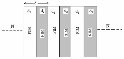
is calculated numerically using transfer matrix method [16,19,26]. The geometry of the structure under study is shown in Fig. 1. The propagation of electromagnetic wave is considered along the x-axis normal to the interface in one-dimensional system composed of periodic arrays of two different materials with a refractive indexn1 andn2 and
layer thicknessd1 and d2. The refractive index profile of the structure
is
n(x) =
n1, 0< x < d1
n2, d1< x < d (1)
withn(x) =n(x+d). Here,d=d1+d2 is the period of the lattice (or
lattice constant).
To solve the electric field vectors of the Bloch wave,we used translational matrix method [16,25]. The electromagnetic field distribution within each layer can be expressed as the sum of right-and left-hright-and side propagating waves. The electric field within the both layers of thenth unit cell can be written as:
E1(x) =
ane−ik1(x−nd
+bneik1(x−nd)
eiωt E2(x) =
cne−ik2(x−nd
+dneik2(x−nd)
eiωt (2) whereki=niω
c 2
−β2 1/2
= niω
Figure 1. Schematic representation of the proposed multilayer structure.
εi and µi are the dielectric permittivity and magnetic permeability of the constituent layers. The coefficients an, bn,cn,and dn are related through the continuity conditions at the interfaces x = (n−1)d and x = (n−1)d+d2. This continuity condition leads to the matrix
equations,which relates the coefficient in the first layer of thenth cell, is given as:
an−1
bn−1
=Tn anbn
(3)
whereTn is called the transfer matrix given by Tn= CA BD
(4)
The matrix elements A,B,C and D are given by: A = eik1d1 cosk
2d2+
1 2i
η+1
η
sink2d2
;
B = e−ik1d1 1
2i
η− 1 η
sink2d2
;
C = eik1d1 −1
2i
η−1 η
sink2d2
&
D = e−ik1d1 cosk
2b−
1 2i
η+ 1
η
sink2d2
(5)
The parameter η depends on the polarizations. For the TE- and TM-mode of polarizations,η is given by
ηTE=
k1
k2
and ηTM=
k1n22
k2n21
For finite stacks the coefficients of right and left hand sides propagating waves in both sides of the multiplayer structure aN and bN,are calculated by multiplying transfer matrix of each cell as [26];
a0
b0
=T1T2. . . TN aNbN
, (7)
whereN is the total number of the cell. The coefficient of reflection is given by solving above matrix equation with the conditionbN = 0 as:
rN = b0 a0 . (8)
Thus the reflectivity (or reflectance) of the structure may be calculated as:
RN =|rN|2. (9) Now,according to Bloch theorem,the electric field vector is of the form E = EK(x)ei(ωt−Kx),where EK(x) is periodic with the period ‘d’. For to determine ofK as a function of eigen value,the equation is written as A B C D an bn
=eiKd anb n
(10)
The solution of this matrix equation leads to the dispersion relation for the PC structure containing the alternate stack of positive index materials (PIMs) is given by:
K(ω) =
1 d
cos−1 cos (k1d1)cos (k2d2)−
1 2 η+1 η
sin(k1d1)sin(k2d2)
(11)
The dispersion relation for the PC structure containing the alternate layer of positive index material (PIM) and negative index material (NIM) is given by [15]:
K(ω) =
1 d
cos−1cos (k1d1)cosh(k2d2)−
1 2
η+1
η
sin(k1d1)sinh(k2d2)
(12)
which is different from the normal PC structure,since for LHMs,k2 <0
(because n2<0).
homogeneous and isotropic periodic dielectric stack,kis the dispersion relation of photonic crystals i.e.,K(ω). This dispersion relation shows the radiation modes of the photonic crystal: if wave function can also be calculated. In addition to the eigen frequency and eigen function, there are several parameters that characterized the radiational waves, one of them is the wave velocity. In contrast to the case particles for which the velocity has single meaning; waves have three different kinds of velocities i.e.,phase velocity,group velocity and energy velocity. These velocities are equal to each other in uniform materials with dielectric contrasts is real and independent of frequency. So that effective phase index is neff(p) = vcp [27]. The phase velocity is
defined as the velocity of the propagation of an equi-phase surface as discussed earlier in this section. This velocity has a definite meaning, for example,for plane waves and spherical waves for which equi-phase surface can be defined without ambiguity. In the photonic crystals, however,the equi-phase surface can not be defined rigorously,since its eigen function is a superposition of plane waves. This means that the phase velocity can not defined appropriately in the photonic crystals [28,29]. Hence, the calculation of the group velocity is an essential task for the understanding of their optical properties. The group velocity of the radiation modes has a very important role in light propagation and optical response in photonic crystals. The group velocity and effective group index in one-dimensional photonic crystal, which is given by:
vg = dω
dk(ω) and neff(g) = c vg
(13)
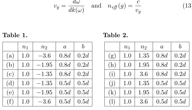
Table 1.
n1 n2 a b
(a) 1.0 −3.6 0.8d 0.2d (b) 1.0 −1.95 0.8d 0.2d (c) 1.0 −1.35 0.8d 0.2d (d) 1.0 −1.35 0.5d 0.5d (e) 1.0 −1.95 0.5d 0.5d (f) 1.0 −3.6 0.5d 0.5d
Table 2.
n1 n2 a b
3. RESULTS AND DISCUSSION
In this section,we have studied the dispersion characteristics,group velocities and effective group indices of the structure containing alternate layers of PIM-NIM and the results are compared with the
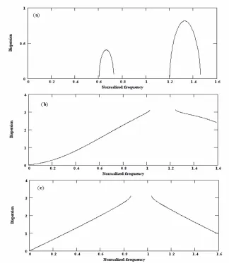
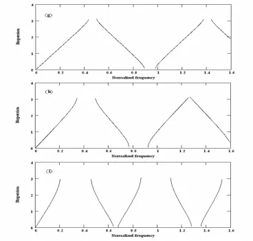
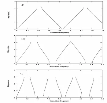
Figure 2. Band structures (xd) versus normalized frequency (in units of c/d) with 0.8d and 0.2d of thicknesses of PIM-NIM respectively (a) n1 = 1.0, n2 = −3.6; (b) n1 = 1.0, n2 = −1.95; (c) n1 = 1.0,
conventional structure consisting alternate layers of PIM-PIM. For the numerical calculations refractive indices of the alternate layers and their thickness are shown in Tables 1 and 2.
The dispersion curves calculated from Equations (12) for the photonic crystal containing PIM-NIM materials,physical parameters given in Table 1,are shown in the Fig. 2 & Fig. 3. Using Equation (11),
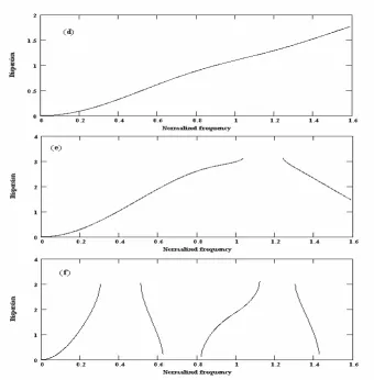
Figure 3. Band structures (xd) versus normalized frequency (in units of c/d) with 0.5d and 0.5d of thicknesses of PIM-NIM respectively (d) n1 = 1.0, n2 = −1.35; (e) n1 = 1.0, n2 = −1.95; (f) n1 = 1.0,
the dispersion curve for the conventional photonic crystal containing PIM-PIM materials,physical parameters given in Table 2,are shown in the Fig. 4 & Fig. 5. From the study of these figures,it is found that the structure containing the alternate layers of PIM-NIM have larger band gaps than those of PIM-PIM structures in a given normalized frequency range (in units ofc/d). Also it is found that forn1 = 1.0,and
n2=−3.6,a= 0.8dandb= 0.2dwheredis total thickness of lattices,
Fig. 2(a),the nature of curve is different than normal dispersion curves and the width of photonic band gap is maximum among the structures considered here shown in Fig. 4(i). But for the structures in which n1 = 1.0, n2 = −1.35, a = 0.8d & b = 0.2d and n1 = 1.0,
n2 = −1.95, a = 0.8d & b = 0.2d,Fig. 2(c) & Fig. 2(b),the nature
of the dispersion curve is usual as for the normal photonic band gap containing PIM-PIM materials shown in the Figs. 4(g) and 4(h). From these results it may be inferred that when the difference of refractive
index between the two layers is less than−1,the structure shows the normal dispersion curves as obtained for the normal photonic band gap containing PIM-PIM materials. While for the structure where the difference of refractive index between the two layers is greater than−1
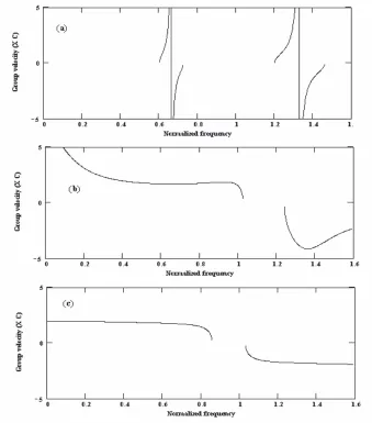
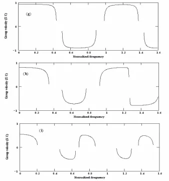
Figure 6. Group velocities (m/s) versus normalized frequency (in units ofc/d) with 0.8dand 0.2dof thicknesses of PIM-NIM respectively (a) n1 = 1.0, n2 = −3.6; (b) n1 = 1.0, n2 = −1.95; (c) n1 = 1.0,
and a = 0.8d, b = 0.2d,the structure shows the abnormal dispersion curves. It is also interesting to note that through the difference in refractive index of the two layer is greater than−1,the structure shows that the normal dispersion curves for lattice parametersa= 0.5dand b = 0.5d shown in Figs. 3(d),3(e) & 3(f); Figs. 5(j),5(k) & 5(l).
Figure 7. Group velocities (m/s) versus normalized frequency (in units ofc/d) with 0.5dand 0.5dof thicknesses of PIM-NIM respectively (d) n1 = 1.0, n2 = −1.35; (e) n1 = 1.0, n2 = −1.95; (f) n1 = 1.0,
Moreover,for a = 0.5d, b = 0.5d width of the forbidden band is much smaller then that of the structure containing alternate layers of PIM-PIM for the same lattice parameters,also the number of bands is much lesser. The group velocities and effective group indices of the conventional photonic crystal are shown in Figs. 8(g),8(h),8(i); Figs. 9(j),9(k),9(l) and Figs. 12(g),12(h),12(i); Figs. 13(j),13(k),
13(l) respectively. The study of group velocities and effective group indices in the conventional photonic crystal shown in Figs. 6(a),6(b), 6(c); Figs. 7(d),7(e),7(f) and Figs. 10(a),10(b),10(c); Figs. 11(d), 11(e),11(f) respectively. The group velocity tends to zero at the edges of the bands and it becomes negative in certain range of normalized
frequency for each conventional photonic crystal. But for the photonic crystal with PIM-NIM for whichn1= 1.0,andn2 =−3.6,a= 0.8dand
b = 0.2d,group velocity as well as the effective group index becomes
Figure 10. Effective group indices versus normalized frequency (in units ofc/d) with 0.8dand 0.2dof thicknesses of PIM-NIM respectively (a) n1 = 1.0, n2 = −3.6; (b) n1 = 1.0, n2 = −1.95; (c) n1 = 1.0,
exactly equal to zero at certain value of normalized frequency is shown in Figs. 6(a) and 10(a) respectively. In addition to this,the high positive and negative values of group velocity and effective group index is found inn1= 1.0,andn2 =−3.6,a= 0.8dandb= 0.2d. Moreover,
the photonic crystal structure containing PIM-NIM,the value of group
Figure 11. Effective group indices versus normalized frequency (in units ofc/d) with 0.5dand 0.5dof thicknesses of PIM-NIM respectively (d) n1 = 1.0, n2 = −1.35; (e) n1 = 1.0, n2 = −1.95; (f) n1 = 1.0,
velocity is found larger than the speed of light at the certain range of normalized frequency,which is given superluminal behavior. But for structure containing PIM-PIM,the group velocity is always found less than the speed of light through it becomes negative at the certain range of frequency. Thus,we have concluded that the PCs containing PIM-NIM have found the group velocity greater than the speed of light in vacuum. It is noticed that the values of the group velocity is become zero,negative and positive at certain range of frequencies. However the conventional photonic crystal,the group velocity is found less than
Figure 13. Effective group indices versus normalized frequency (in units ofc/d) with 0.5dand 0.5dof thicknesses of PIM-PIM respectively (j)n1= 1.0,n2 = 1.35; (k)n1 = 1.0,n2= 1.95; (l) n1= 1.0,n2 = 3.6.
4. CONCLUSIONS
The value of group velocity of the one dimensional photonic crystal containing PIM-NIM is grater than the velocity of light in certain range of normalized frequency,which gives superluminal behavior. But the periodic structure containing PIM-PIM,the group velocity is always less than the velocity of light though it becomes negative in a certain range of frequency. Thus,we concluded that the group velocity of the period structure containing PIM-NIM have greater than the velocity of light,in addition to zero,negative and positive value; where as for the photonic crystal having PIM-PIM periodic materials,the group velocity is less than velocity of light though it is positive and negative. Thus,the photonic crystal containing PIM-NIM can be used to trap the photons i.e.,light localization occurs without introducing the defects.
ACKNOWLEDGMENT
The authors thank to the Central Library,C.S.J.M. University,Kanpur for providing library facilities,and Khem B. Thapa is grateful to the Prof. D. Saran,Director,U.I.E.T,C.S.J.M. University,Kanpur-208024 (UP) for his encouragements.
REFERENCES
1. Yablonovitch,E.,“Inhibited spontaneous emission in solid-state physics and electronics,” Phys. Rev. Lett.,Vol. 58,2059–2062, 1987.
2. John,S.,“Strong localization of photon in certain disordered dielectric superlattice,”Phys. Rev. Lett.,Vol. 58,2486–2489,1987. 3. Guida,G.,A. de Lustrac,and A. Priou,“An introduction to pho-tonic band gap (PBG) materials,” Progress In Electromagnetics
Research,PIER 41,1–20,2003.
4. Rojas,J. A. M.,J. Alpuente,J. Pi˜neiro,and R. S´ anchez,“Rig-orous full vectorial analysis of electromagnetic wave propagation in 1d Inhomogeneous media,” Progress In Electromagnetics
Re-search,PIER 63,89–105,2006.
5. Banerjee,A.,S. K. Awasthi,U. Malaviya,and S. P. Ojha,“Design of a nano-layered tunable optical filter,” J. of Modern Optics, Vol. 53,1739–1752,2006.
multilayer fibonacci structures,” Progress In Electromagnetics
Research,PIER 59,69–83,2006.
7. Veselago,V. G.,“The electrodynamics of substances with simultaneously negative values of ε and µ,” Soviet Physics
Uspekh1,Vol. 10,509–514,1968.
8. Pendry,J. B.,A. J. Holden,W. J. Stewart,I. Youngs,“Extremely low frequency plasmons in metallic mesostructures,” Phys. Rev.
Lett.,Vol. 76,4773–4778,1996.
9. Pendry,J. B.,“Negative refraction makes a perfect lens,” Phys.
Rev. Lett.,Vol. 85,3966–3970,2000.
10. Kong,J. A.,“Electromagnetic wave interaction with stratified negative isotropic media,” Progress In Electromagnetics Research, PIER 35,1–52,2002.
11. Zhang,Y.,T. M. Grzegorczyk,and J. A. Kong,“Propagation of electromagnetic waves in a slab with negative permittivity and Negative permeability,” Progress In Electromagnetics Research, PIER 35,271–286,2002.
12. Smith,D. R.,W. J. Padilla,D. C. Vier,S. C. Nemat-Nasser, and S. Schultz,“Composite medium with simultaneously negative permeability and permittivity,” Phys. Rev. Lett.,Vol. 84,4184– 4188,2000.
13. Shelby,R. A.,D. R. Smith,and S. Schultz,“Experimental verification of a negative index of refraction,” Science,Vol. 292, 72–75,2001.
14. Ramakrishna,S. A.,“Physics of negative index materials,”Report
Prog. Phys.,Vol. 68,449–525,2005.
15. Zhang,Z. M. and C. J. Fu,“Unusual photon tunneling in the presence of a layer with a negative refractive index,”Appl. Phys.
Lett.,Vol. 80,1097–1102,2002.
16. Wu,L.,S. He,and L. Shen,“Band structure for a one-dimensional photonic crystal containing left handed materials,”Phys. Rev. B, Vol. 67,235103-12,2003.
17. Jiang,H.,H. Chen,H. Li,Y. Zhang,J. Zi,and S. Zhu,“Properties of one dimensional photonic crystals containing single-negative materials,” Phys. Rev. E,Vol. 69,066607-10,2004.
18. Bria,D.,B. Djafari-Rouhani,A. Akjouj,L. Dobrzynski, J. P. Vigneron,E. H. ElBoudouti,and A. Nougaoui,“Band structure and omni directional photonic band gaps in lamellar structure with left handed materials,” Phys. Rev. E.,Vol. 69, 066613-12,2005.
band gaps in one dimensional left handed periodic structure,”
Phys. Rev. Lett.,Vol. 95,193903-4,2005.
20. Wu,R. X.,“Wave polarization and left-handed materials in metallic magnetic thin films,” Progress In Electromagnetics
Research Symposium,459–463,Hangzhou,China,August 2005.
21. Shu,W. and J. M. Song,“Complete mode spectrum of a grounded Dielectric slab with double negative metamaterials,” Progress In
Electromagnetics Research,PIER 65,103–123,2006.
22. Singh,S. K.,J. P. Pandey,K. B. Thapa,and S. P. Ojha, “Structural parameters in the formation of omnidirectional high reflectors,” Progress In Electromagnetics Research,PIER 70,53– 78,2007.
23. Nicolae,C.,R. M. Osgood,Jr.,S. Zhang,and S. R. T. Brueck, “Zero average refractive index band gap in PC superlattices,” J.
Opt. Soc. Am. B,Vol. 23,506–512,2006.
24. Jiang,H.,H. Chen,and S. Zhu,“Localized gap-edge fields of one dimensional PC with anεnegative and aµnegative defect,”Phys.
Rev. E.,Vol. 79,0466601-8,2006.
25. Nanda,L.,A. Basu,and S. A. Ramakrishna,“Delay times and detector times for optical pulses traveling plasma and negative refractive media,”Phys. Rev. B,Vol. 74,036601-7,2006.
26. Yeh,P.,Optical Waves in Layered Media,John Wiley and Sons, New York,1988.
27. Dowling,J. P. and C. M. Bowden,“Anomalous index of refraction in photonic bandgap materials,”J. Mod Optics,Vol. 41,345–352, 1994.
28. Sakoda,K.,Optical Properties of Photonic Crystal,Springer Verlag Press,Germany,2001.