Structural Design of Korean Next Generation Reactor
Kwang-Ho Joo 1),
Chong-Hak Kim 1)1) Korea Electric Power Research Institute, KEPCO, TAEJON, KOREA
ABSTRACT
The Korean Next Generation Reactor (KNGR), as a pressurized water reactor which succeeds the
korean standard nuclear power plant, was decided to be developed in accordance with the project, G-7, by
Korean govemment in 1992. It is currently promoting in the form of a cooperation by industries,
academies and research institutes to develop a standard design on the evolutionary nuclear power plant in
the level of 1,400MWe at each phase not only to enhance safety and economics but also to meet electric
power needs in terms of a long-term plan for the electric power demand and supply. In the phase III of
its technical development, from March 1999 to December 2001, the design targets to 1) obtain the
standard design certification, and 2) establish an optimized design for economics improvement, and 3)
develop the design of long-lead items. This study addresses the issues of the KNGR with two intents. The
first is to introduce the main characteristics of design for KNGR briefly. The second purpose of this paper
is to describe the current situation on its design, focusing on the characteristics of building arrangement on
the Nuclear Island such as containment building, auxiliary building, and compound building with the
seismic analysis and structural design of them.
1. INTRODUCTION
The aim of KNGR is to establish great safety and economics in order to cope with severe accident,
people's agreement on the construction of nuclear power plants and competition with other energy
resources. The work of KNGR is one of the G-7 projects, and the related organizations with the nuclear
field such as government, universities, industries, and research institutes are participating in this project. For
this, phasic studies like conceptual and basic designs have been carried out separately at each stage. At
present, the standard design on KNGR is being performed and we are carrying on a plan to complete a
construction of the expected KNGR unit 1 in 2010. Table 1 shows the main characteristics of the design
on KNGR [1].
Table 1. Main Characteristics of Design for KNGR
Electric Power
Design Life Time
Core Damage Frequency
RWST
Free Volume
... : ... ... ... ... ... ...
1,400MWe 0.412 Mpa
60 years
10"/yr
IRWST
9.12 × 10⁴ m e
Design Basis Pressure
Severe Accident Pressure
Design Basis Earthquake
Site Conditions
Base Mat
0.793 Mpa
SSE of 0.3g
Rock and Soil Sites
Common Mat
SMiRT 16, Washington DC, August 2001 Paper # 1410
2. CHARACTERISTICS OF BUILDING ARRANGEMENT FOR KNGR
The building of KNGR is divided into three sections : Nuclear Island (NI), Turbine Island (TI) and
Site Specific. Whereas NI is composed of containment building, auxiliary building, and compound building,
TI consists of turbine generator building and switchgear building, and Site Specific is made up of the rest
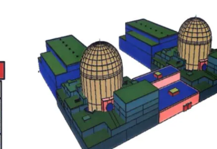
of structures except NI and TI, which is going to be developed after deciding a site [2]. The KNGR not
only satisfies safety, independence of system, and reinforced regulatory requirement but also adapts an
arrangement pattern of sliding along which is able to improve the applicability of a site [3]. (see the
figures 1, 2.)
S W G R .
Aux. Bldg.
Fuel
Bldg
Figure 1. Building Arrangement of KNGR Figure 2. Overview of KNGR
The containment building is made of the structures of prestressed concrete and reinforced concrete,
and surrounded by the auxiliary building. The super-structure is, however, structurally separated from the
auxiliary building. The auxiliary building, as a pattern of wrap-around completely surrounding the
containment building, was designed under the concept of quadrant division suitable for the four-train safety
related systems. The primary and the secondary auxiliary buildings, which are separated each other in the
first generation standard nuclear power plant (Ulchin units 3, 4 [4]), the fuel building, and the emergency
diesel generator building are incorporated into one in the KNGR
The turbine building is arranged to accommodate the turbine of 132 centimeters blades for the first
time at home and we tried to improve the usage of space and the operability/maintainability for the
electrical equipment, centralizing the switchgears into a specific switchgear building. We also took the
1
improved economics into consideration by arranging the common facilities related to radioactive wastes,
access control and hot machines between two KNGR units, namely, putting a compound building between
the auxiliary buildings [5].
3. SEISMIC ANALYSIS
The KNGR is designed with a standardized concept so that we are able to construct on various sites
rock. We have assumed eight soil conditions to consider various characteristics and configurations of the
soil, and carried the Soil-Structure Interaction (SSI) analysis on them respectively, and then enveloped the
results to cover the site conditions. In addition, the KNGR has adapted the seismic input motion in its
design, which has a considerable conservatism comparatively. The KNGR has increased, especially, the
maximum peak ground acceleration of Safe Shutdown Earthquake (SSE) up to 0.3g, a level of most
evolutionary nuclear power plants in foreign countries, in terms of 1) results from a past survey on
proposed sites for the nuclear power plant, and 2) recently changed rules on it in the United States.
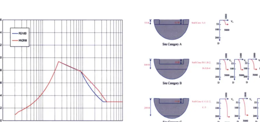
Meanwhile Operating Basis Earthquake (OBE) was eliminated from the design [6]. A design ground
response spectrum is adapted as the seismic input motion, which has been enriched in high frequency
range more than that of standard response spectrum presented in the Regulatory Guide 1.60 [7]. (see the
figure 3.)
The KNGR has adapted the concept of standard design with increased flexibility with the site
conditions for it, accomplishing the SSI analysis which involves rock and soil sites and considering the site
envelope characteristics of the soil properties. The site envelope characteristics of KNGR are as following
[8]:
• Maximum peak ground acceleration of SSE • 0.3 g
• Usage of Regulatory Guide 1.60 enriched in high frequency range
• Soil profile : Three site categories with each different soil layer thickness (see the figure 4.)
• Soil condition : Eight soil conditions which cover the main frequencies of free field ground
response spectrum
..,.1.0 c ._9
~Q8
O6
(:!0
01
I /
/ /
/
f,.
/
\
Figure 3. Seismic Input Motion
53 I1~" s,)il Case ,\ - I 5 3 ~ V,
100
2oo~-
Site Category A D
IT ~ ... ' ... 53 ~ V ' 5 3 ~-'~V~3 ~ V'53 ~ V'
Site Category B D D D D
Soil C';isc C-I {'-2 5 3 ~ "~
2001 C-3 I00 100 100
2 200 200
Site Category C O 5OOO O 5ooo D 5oo0
Figure 4. Generic Soil Site Category
4. STRUCTURAL DESIGN OF CONTAINMENT BUILDING CONSIDERING SEVERE ACCIDENT
The containment building is designed 1) to protect employees in nuclear power plant and neighbors
from the radioactive exposure, during the normal operation and accidents as well, and 2) to preserve the
systems and components inside the containment building from the external events of the possible external
The containment building is carefully designed considering the following issues to have a role as the
last protection barrier in case of design basis accident and severe accident •
• Functional criterion of the containment building" satisfaction of the free volume requirement
prescribed by the Factored Load Category of the ASME Code
• Performance of structural analysis on the temperature and pressure in the event of severe accident
• Performance of analysis on the configuration and materials of the reactor cavity structures taking
into consideration on severe accident
The severe accident refers to any accident that cause core damage beyond the design basis accident
regardless the radioactive leakage. The statute of 10CFR50.34(f) [9], SECY-93-087 [10] has prescribed the
requirements, after the Three Mile Island accident in the U.S.A., on the function of the containment
building as following :
• The containment should maintain its role as a reliable, leak-tight barrier by ensuring that
containment stresses do not exceed ASME Factored Load Category for a minimum period of 24
hours following the onset of core damage, and that following this 24-hour period that
containment should continue to provide a barrier against the uncontrolled release of fission
products.
Like these, the containment building of KNGR is designed to maintain the above functions and also
made of robust prestressed concrete containing sufficient free volume so that it can control hydrogen
during the severe accident. To fulfill these functional requirements, the containment building is requested to
have more advanced design features regarding the safety and reliability. The targets of the related safety
are shown below :
• To maintain the frequency below 106/Ry as for the loss of structural integrity of containment
building which causes the massive outflow of radiation.
• To carry out the containment function even in the severe accident although designed on the
design basis accident, and to satisfy the requirements of 10CFR50.34(f) for at least 24 hours
until the functions of core cooling can recover.
In addition, the KNGR needs to be made to maintain the integrity of intemal structures in the event
of a severe accident, especially, the reactor cavity structure. The reactor cavity structure should be designed
to support the reactor vessel safely even in the core melting accident, when the structure is exposed to a
great energy due to the steam explosion after the reaction between the molten core with high temperature
and water in the reactor cavity. It is also necessary to decide the materials and thickness of the protective
fill concrete over the bottom liner plate after examining the influence of the erosion by the reaction of
concrete and molten core with high temperature and high pressure. It may be an inevitable work to
establish considerable shear friction force to avoid settlement of the upper structure supporting the reactor
vessel from corroding on the cavity wall. The requirements related the reactor cavity structure are as
following : [ 11 ]
• Direct contact between structures of the pressure boundary in the containment building and
molten core should be avoided.
• Evaluation on structures against the pressure load of steam explosion should be performed.
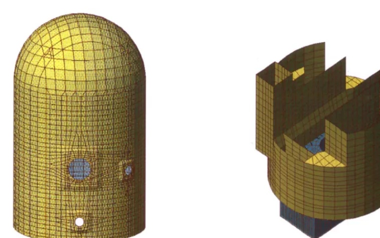
In order to fulfill the above requirements, the reactor cavity structure of KNGR is designed as
following and the analysis models on the containment building and internal structures are shown in the
figures 5--- 7.
• Floor area of the reactor cavity : about 78 m 2 (0.0201 m2/MWt)
• Thickness of the fill concrete : 91 cm
• Materials of the fill concrete" Basaltic concrete
• Designed enough for supporting the reactor vessel when a steam explosion occurs
lli~i
... ...
~
~ ~ . -
~ . .
. , ~ .
Figure 5. Analysis Model of Containment Building Figure 6. Analysis Model of Internal Structures
5. ANALYSIS AND DESIGN ON THE STRUCTURES OF IRWST
In-Containment Refueling Water Storage Tank (IRWST), as an advanced idea of having RWST inside
of the containment building, is one of the crucial designs of KNGR to prepare more effectively for the
severe accident. In order words, the IRWST carries out a role as a supplier to various safe systems and as
a contributor to diminish the core damage frequency and improve the integrity of the containment building,
eliminating the necessity of changing the water source for the reactor core cooling at an emergency. The
IRWST is located in the lower part of the internal concrete structures and is lined with stainless steel liner
plates for preventing from leakage.
The IRWST performs its role, as the first adapted internal structures of the containment building in
KNGR, to store the borated water for refueling, for sprinkling inside containment building, and for
of ring-shaped concrete structures, the system of stainless steel liners and underwater structures. IRWST
structures are designed in accordance with the ACI-349, as seismic category I structures, especially, made
for enduring the dynamic thermal-hydraulic load spouted through the sparger for the safety depressurization
of the reactor after a design basis accident. The main loads we should carefully consider are dead load,
live load, temperature load, seismic load, and thermal-hydraulic load [12].
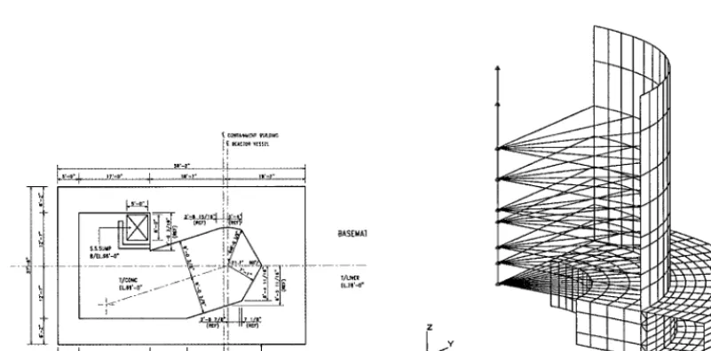
The program of MSC/NASTRAN was used for the IRWST design to think over the effect of
fluid-structure interaction, and the model of 1/4 (see the figure 8.) was adapted for the analysis of it to
take into consideration the effect of an interaction between fluid and structures on the idealized three
dimensional structures. In this model, cover slabs, outer walls, bottom slabs, primary shield walls,
secondary shield walls, fill concrete, and water were included.
.t
Ii,.-o% ,,.-o- +
( ~ r ~ " ii (Rtr)
_,'-o- I .. . . - _[_,' .. . . J-'" . . . !J [ CLP
..-,- !+ ,.-,-
---:j
i ] tr(Rtr)
BASEMAI
T / U ~ R
z
I
Figure 7. Configuration of Reactor Cavity Figure 8. Analysis Model of IRWST
6. CONSIDERATION ON THE DESIGN LIFE TIME FOR 60 YEARS
Whereas the existing nuclear power plants, in general, were designed for about 40 years life of
them, researches on life time management for the operating nuclear power plants have been currently in
progress to enhance the economics of the plants, the KNGR was decided for 60 years design life. There
exists considerable technology development in diagnosis, maintenance and life management for structures of
operating nuclear power plants, and we are adapting a considered design on the aging effect, thinking the
increased design life especially in the evaluation of prestressing loss due to the creep and shrinkage of
concrete and the relaxation of tendon when a design on the post-tensioning system of the containment is
made. We have applied the design parameters after evaluating the loss of effective prestress of the post-
tensioning system according to the design life.
• Coefficient of shrinkage of concrete • 1 2 0 x 1 0 6 cm/cm
• Coefficient of creep of concrete • 0.78×10 .7 cm/cm/Kpa
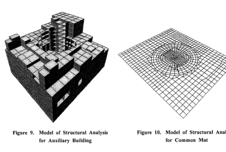
7. ADOPTION OF COMMON MAT
Base mat delivers load of the super-structures to the ground. Common mat is adapted to the main
structures of nuclear power plant such as containment building and auxiliary building, since it is safer for
overturning, sliding, and settlement of the structures. These days, for the base mat of evolutionary light
water reactor under developing, it is apt to use common mat on the containment and auxiliary buildings.
While the existing nuclear power plants selected the divisional concept to accommodate the safety related
systems and facilities of two trains, the KNGR took the concept of quadrant to manage four train systems
in order to improve safety. The auxiliary building, therefore, figures a pattern of wrap-around which
entirely surrounds the containment building unlike the one of previous nuclear power plants, and takes the
common mat with the containment building. (see the figure 9.) Thus, the containment building is located
in the middle of the common mat and the auxiliary building is put against the containment building with
a symmetrical arrangement in order to be profitable for dynamic behavior of the structures due to
earthquakes. However the super-structures of the buildings are structurely separated for no interaction
between each other.
The adoption of the common mat is evaluated as a resonable one in terms of 1) a reinforced
seismic design as a safety requirement for the KNGR, 2) an application of the site envelope characteristics,
3) preparation for severe accident, and 4) more increased design loads comparing to the existing plants.
Common mat, however, may negatively affect the increment of thickness due to the increase of mat size
and an access toward the containment building during construction in comparison with the individual mat.
To solve this problem, studies, on the influence of hydration-heat due to the placement of massive
concrete, on shortening methods for construction period, and on design of the access for construction, are
being carried out. For the analysis of the base mat, the three dimensional finite element model including
the base slabs of containment and auxiliary buildings is used (see the figure 10.) and the soil springs are
adopted for the soil stiffness and uplift of the base mat as well.
Figure 9. Model of Structural Analysis
for Auxiliary Building
Figure 10. Model of Structural Analysis
8. CONCLUSION
So far we have had a brief introduction of the major design concept on structures for KNGR. The
KNGR is currently developing in order to establish a big leap in terms of safety and economics on the
basis of the design, construction and operation, referring to design concept of advanced reactors in the
U.S., Japan and Europe. According to the current power developing program, the KNGR unit 1 is
supposed to start commercial operation in 2010. It is, therefore, necessary to contrive an optimized design
in accordance with safety and economics, consulting a new design concept effectively into the basic
design.
In order to ensure an improvement of design, construction and increased economic effects, the KNGR
project requires the constructibility research team to study furthermore on the topics of modularization plan,
the application of a large capacity crane, the improvement of accessability, the placement of massive
concrete controlling the hydration-heat, and the application of deck plates. In addition, periodical
evaluations on the economics and construction period as well as the probabilistic safety analyses are being
performed, as a general feedback to accommodate a balanced design of the KNGR.
REFERENCES
1. Final Reports for Research and Development on Next Generation Reactor (Phase I), "Conceptual
Design of Next Generation Reactor," Korea Electric Power Research Institute, December 1994.
2. Final Reports for Research and Development on Next Generation Reactor (Phase II), "Basic Design of
Next Generation Reactor," Korea Electric Power Research Institute, February 1999.
3. Interim Reports for Research and Development on Next Generation Reactor (Phase III), "Standardized
Design of Next Generation Reactor," Korea Electric Power Research Institute, October 2000.
4. Ulchin Nuclear Power Plants Unit 3&4 Final Safety Analysis Reports, Korea Electric Power
Corporation, December 1998.
5. General Arrangement for Nuclear Island of Koran Next Generation Reactor, Korea Electric Power
Research Institute, July 2000.
6. Code of Federal Regulations, Title 10, Part 50, Appendix S, "Earthquake Engineering Criteria for
Nuclear Power Plants," January 1997.
7. Regulatory Guide 1.60, "Design Response Spectra for Seismic Design of Nuclear Power Plants,"
December 1973.
8. KNGR Technical Report, "Site Envelope Characteristics," March 1998.
9. Code of Federal Regulations, Title 10, Part 50.34, "Contents of Applications; Technical Information,"
January 1997.
10. SECY-93-087, "Policy, Technical, and Licensing Issues Pertaining to Evolutionary and Advanced
Light-Water Reactor (ALWR) Designs," USNRC, April 1993.
11. Korean Utility Requirement Documentation, Korea Electric Power Research Institute, March 2000.
12. Preliminary Assessment of Sparger Submergence Effects on KNGR IRWST Loads and Structural