Design and Implementation of DSRC
Encoders for Efficient Hardware Utilization
K.Srinath
1, V.Prasad
2P.G. Student, Department of ECE, Shree Institute of Technical Education, Tirupati, India1
Assistant Professor, Department of ECE, Shree Institute of Technical Education, Tirupati, India 2
ABSTRACT: The dedicated short-range communication (DSRC) system is the evolving technique used in the field of intelligent transport system (ITS) and Electronic Toll Collection (ETC). The DSRC standards employs FM0 and Manchester encoding techniques to obtain dc-balance and enhances signal reliability. The codeword structure of FM0 and Manchester are different, thus limiting the hardware potential of existing DSRC systems. In this paper similarity oriented logic simplification (SOLS) technique is proposed to fully re-utilise the existing hardware and behavioural model is simulated using XILINX 14.1 software and outputs are verified using XILINX VIRTEX-5 kit. This encoding technique fully supports DSRC standards of America, Europe and Japan. This paper proposes the technique to improve reliable performance over existing DSRC systems.
KEYWORDS: FM0 and Manchester Encoding, DSRC, SOLS, Intelligent Transport System (ITS), Electronic Toll Collection (ETC).
I. INTRODUCTION
The dedicated short-range communication (DSRC) [1] is short range to medium range communication which can be communicated one or both ways in vehicle to vehicle (V2V) or vehicle to roadside ( V2R) communications system. In vehicle -to- vehicle the DSRC equipment send and receives messages from one vehicle to other vehicle within the range. This messages include road safety instructions , traffic intimations, inter car distance, intersection warnings and collision alarms. The vehicle to roadside DSRC systems is mainly used for intelligent transport systems such as electronic toll collection, parking payments and gas refuelling [2].
The types of encoding used in communication convert information into a form suitable for transmission. Encoding techniques can also be used for security purposes. In general, different types of encoding can be used for serial communication [3]. There are many ways to encode the data such as Miller encoding, Manchester encoding, FM0, NRZ, FM1, RZ, etc. This type of encoding is used on the transistor level, so it can be used with optical communication, minimizing the critical path, area, delay, and buffer size by adding a minimum number of buffers [4]. A baseband processor such as a UHF RFID Reader, PIE encoder, FM0 decoder, or Miller decoder are used for encoding and decoding purposes, achieving higher efficiency and accuracy [5]. But in order to do this, it needs a high frequency clock [6]. The paper is organized as follows: The description of the encoding techniques is given in Section II. In Section III, we give a hardware description for FM0/Manchester encoders . In Section IV, we describe FM0/Manchester encoder using SOLS technique. In Section V, the simulation results are verified and conclusion is given .
II. RELATED WORK
Manchester Encoding Technique
transmitted. Compared to all other encoding methods, Manchester code follows an algorithm to encode the data. It always produces a transition at the center of the bit. It contains sufficient information to recover a clock. So if the data rate is twice, sufficient clock information can be recovered from the data stream so that separate clocks are not needed. As a result, the electrical connection using Manchester code is easily a galvanic ally isolator (it is the principle of isolating functional sections of electric systems to prevent current flow) using a network isolator for simple one-to-one isolation transformation. Therefore, while transmitting the data, the number of wires is minimized, which is used to reduce the noise and transmission power.
Logic ―1‖ represents the transition from HIGH to LOW.
Logic ―0‖ represents the transition from LOW to HIGH.
To obtain a high speed, provide a synchronized data source as the first clock pulse for input data. While transmitting the data, it is a digital encoding in which data transmission bits are represented by transitions from one logic to another logic. The length of each bit is set as default, and it consumes the signals as self-clocking. The direction of the transition decides the state of the bit.
It is sometimes necessary to have a transition in the middle of a bit so that the transition obtained at the beginning period is disregarded.
Figure 1. Manchester Encoding
The operation of the Manchester encoder is an exclusive OR of the signal with the clock signal. Then, the rising edge will be obtained when the bit value is zero and the falling edge is opposite case. It doesn’t take on a zero value.
Table 1. Operation of Manchester encoding
The detailed explanation of Manchester encoding is when the input is 0 and the clock is 0. Then, it produces a corresponding output of zero. If the original data is 0 and the clock is 1, then the output is one. If the original data is given as 1 and clock is 0, the corresponding output is one. When the original data is given as 1 and the clock is 1, the corresponding output is zero.
Figure 2. FSM for Manchester encoder
Table 2. For state machine diagram of Manchester encoder
The main advantage is that the signal synchronizes itself, minimizes the error rate, and optimizes the reliability. The drawbacks to this encoding are that more bits are needed to transmit in the Manchester encoding signal than the original signal, and it needs more bandwidth.
FM0 Encoding Technique
FM0 is also known as Biphase space encoding. A transition is present on every bit and an additional transition may occur in the middle of the bit. Here the data rate is twice. Sufficient clock information can be recovered from the data stream so that a separate clock is not needed. Therefore, for transmission, the number of wires is minimized.
Logic ―0‖ represents the transition in the center of the bit.
Logic ―0‖ represents the no transition from the center of the bit.
Figure 3. FM0 Encoding
The block diagram has an XOR gate, DFF, inverter, and MUX. For example, the XOR gate has one input as feedback that is 0, and another input as 1. This XOR output is given to DFF1, and it also has a CLK signal with an output of 1. Another DFF2 has an input as 1 and CLK. The output is 1. Both DFF outputs are given to MUX, and also it has a CLK with it that produces the output based on selection lines. If the selection line is 0, it produces the output as DFF1 as FM0 output. Otherwise, the selection line is 0 and produces an output as DFF2 or FM0 output.
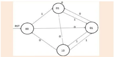
Figure 4. FSM for FM0 encoder
The four states of 00, 01, 10, and 11 are available, along with RST. The transition is obtained based on 1 and 0. The initial state, reset, is 1. Then the next state will be 00. After the reset it will always be 0. When the input is 0, and the current state is 00, the next state is 11. If the input is 1, and the current state is 00, the next state is 01. If the input is 0, and the current state is 01, the next state is 10. If the input is 1, and the current state is 01, the next state is 11. When the input is 0, and the current state is 10, the next state is 00. If the input is 1, and the current state is 10, the next state is 11. If the input is 0, and the current state 11, the next state is 01. And if the input is 1, and the current state is 11, the next state is 10.
III. HARDWARE ARCHITECTURE OF FM0/MANCHESTER CODE
Figure 5. Hardware Architecture
This is the hardware architecture of the fm0/Manchester code. the top part is denoted the fm0 code and then the bottom part is denoted as the Manchester code. in fm0 code the DFFA and DFFB are used to store the state code of the fm0 code and also mux_1 and not gate is used in the fm0 code. when the mode=0 is for the fm0 code. the Manchester code is developed only using the XOR gate and when the mode=1 is for the Manchester code. the hardware
utilization rate is defined as the following
Table 4. HUR of FM0 and Manchester encodings
For both the encoding methods the total components is 7.for the fm0 code the total component is 7 and then the active component is 6.in Manchester code the total component is 7 the active component is 2. in both coding having 98 transistors are used without SOLS. The fm0 having 86 transistor, and then the Manchester having the 26 transistor. the average for both coding is 56 transistors. In proposed work reduce the total components from 7 to 6 and reduce the transistor counts. In this paper two multiplexer is used in proposed work reduce two multiplexer from one multiplexer, when reduce the multiplexer the total components are reduced the area and then the power consumption also reduced.
IV. FM0/MANCHESTER CODE USING SOLS TECHNIQUE
The SOLS technique is classified into two parts area compact retiming and balance logic operation sharing
A. area compact retiming
For fm0 the state code of the each state is stored into DFFA and DFFB .the transition of the state code is only depends on the previous state of B(t-1) instead of the both A(t-1) and B(t-1)
Figure 6.FigureArea Compact Retiming Figure 7.FM0 Encoding without Area Compact Retiming
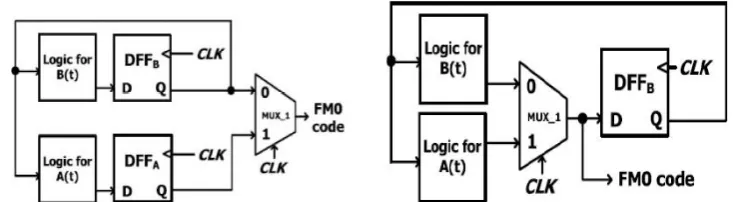
Figure 8. FM0 Encoding with Area Compact Retiming
Thus, the FM0 encoding just requires a single 1-bit flip-flop to store the previous value B(t−1). If the DFFA is directly removed, a non synchronization between A(t) and B(t) causes the logic fault of FM0 code. To avoid this logic-fault, the DFFB is relocated right after the MUX−1, where the DFFB is assumed be positive-edge triggered flip flop. At each cycle, the FM0 code, comprising A and B, is derived from the logic of A(t) and the logic of B(t), respectively. The FM0 code is alternatively switched between A(t) and B(t) through the MUX−1 by the control signal of the CLK. In the Q of DFFB is directly updated from the logic of B(t) with 1-cycle latency. when the CLK is logic-0, the B(t) is passed through MUX−1 to the D of DFFB. Then, the upcoming positive-edge of CLK updates it to the Q of DFFB. the timing diagram for the Q of DFFB is consistent whether the DFFB is relocated or not. The B(t) is passed through MUX−1 to the D of DFFB. Then, the upcoming positive-edge of CLK updates it to the Q of DFFB. the timing diagram for the Q of DFFB is consistent whether the DFFB is relocated or not. The transistor count of the FM0 encoding architecture without area-compact retiming is 72,and that with area-compact retiming is 50. The area-compact retiming technique reduces 22 transistors.
B. balance logic operation sharing
The Manchester encoding is derived using the XOR operation. the equation of the XOR gate is given below.
X ⊕CLK=X CLK+~ X CLK
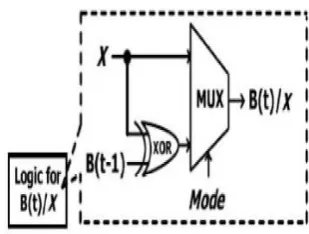
The concept of balance logic-operation sharing is to integrate the X into A(t) and X into B(t).the fm0 and Manchester logics have a common point of the multiplexer like logic with the selection of the CLK. the diagram for the balance logic operation sharing given the following.
The A(t) can be derived from an inverter of B(t − 1), and X is obtained by an inverter of X. The logic for A(t)/X can share the same inverter, and then a multiplexer is placed before the inverter to switch he operands of B(t − 1) and X. The Mode indicates eitherFM0 or Manchester encoding is adopted. The similar concept can be also applied to the logic for B(t)/X
Nevertheless, this architecture exhibits a drawback that the XOR is only dedicated for FM0 encoding, and is not shared with Manchester encoding. Therefore, the HUR of this architecture is certainly limited. The X can be also interpreted as the X � 0, and thereby the XOR operation can be shared with Manchester and FM0 encodings, where the multiplexer irresponsible to switch the operands of B(t−1) and logic-0. This architecture shares the XOR for both B(t) and X, and there by increases the HUR. When the FM0 code is adopted, the CLR is disabled, and the B(t −1) can be derived from DFFB .Hence, the multiplexer can be totally saved, and its function can be completely integrated into the relocated DFF. The logic for A(t)/X includes the MUX−2 and an inverter. Instead ,the logic for B(t)/X just incorporates a XOR gate. In the logic for A(t)/X, the computation time of MUX−2is almost identical to that of XOR in the logic for B(t)/X. However, the logic for A(t)/X further incorporates an inverter in the series of MUX−2. This unbalance computation time between A(t)/X and B(t)/X results in the glitch to MUX−1,possibly causing the logic fault on coding. To alleviate this unbalance computation time, the architecture of the balance computation time between A(t)/X and B(t)/X The XOR in the logic for B(t)/X is translated into the XNOR with an inverter, and then this inverter is shared with that of the logic for A(t)/X. This shared inverter is relocated backward to the output of MUX−1. Thus, the logic computation time between A(t)/X and B(t)/X is more balance to each other.
Table 5. Performance Profiles of Previous Encoding Techniques
Figure 10. Simulation of FM0/Manchester Encodings
Figure 11. FM0 and Manchester Encoding dumped on to XILINX VIRTEX 5 FPGA kit
V. CONCLUSION
to reduce the transistors. The balance logic-operation sharing efficiently combines FM0 and Manchester encodings with the identical logic components.
REFERENCES
[1] F. Ahmed-Zaid, F. Bai, S. Bai, C. Basnayake, B. Bellur, S. Brovold, et al., ―Vehicle safety communications—Applications (VSC-A) final report,‖ U.S. Dept. Trans., Nat. Highway Traffic Safety Admin., Wash-ington, DC, USA, Rep. DOT HS 810 591, Sep. 2011.
[2] J. B. Kenney, ―Dedicated short-range communications (DSRC) standards in the United States,‖ Proc. IEEE, vol. 99, no. 7, pp. 1162–1182, Jul. 2011.
[3] P. Benabes, A. Gauthier, and J. Oksman, ―A Manchester code generator running at 1 GHz,‖ in Proc. IEEE, Int. Conf. Electron.,Circuits Syst.,vol. 3. Dec. 2003, pp. 1156–1159.
[4] H. Zhou, A. Aziz, ―Buffer minimization in pass transistor logic,‖ IEEE Trans. Comput. Aided Des. Integr. Circuits Syst., vol. 20, no. 5, pp. 693-697, May 2001. Article (CrossRef Link)
[5] I. Ismail, A. Ibrahim, ―Modeling and Simulation of Baseband Processor for UHF RFID Reader on FPGA,‖ International Journal of Electrical and Electronic Systems Research, vol. 6, pp. 54-66, Jun. 2013. Article (CrossRef Link)
[6] S. Suresh ―Vhdl Implementation of Manchester Encoder and Decoder,‖ International Journal of Electrical, Electronics and Data Communication, vol. 1, no. 2, pp. 2320-2084, Apr. 2013. Article (CrossRef Link)
[7] A. Karagounis, A. Polyzos, B. Kotsos, and N. Assimakis, ―A 90nm Manchester code generator with CMOS switches running at 2.4 GHz and 5 GHz,‖ in Proc. 16th Int. Conf. Syst., Signals Image Process., Jun. 2009, pp. 1–4.
[8] Y.-C. Hung, M.-M. Kuo, C.-K. Tung, and S.-H. Shieh, ―High-speedCMOS chip design for Manchester and Miller encoder,‖ in Proc. Intell. Inf. Hiding Multimedia Signal Process., Sep. 2009, pp. 538–541.